
Related Manuals for Belden Hirschmann OCTOPUS 8TX PoE-EEC


Summary of Contents for Belden Hirschmann OCTOPUS 8TX PoE-EEC
- Page 1 User Manual Installation IP65/67 Switch OCTOPUS 8TX-EEC OCTOPUS 8TX PoE-EEC OCTOPUS 8TX-EEC-M Installation OCTOPUS 8TX-EEC Technical support Release 07 01/2021 https://hirschmann-support.belden.com...
- Page 2 The naming of copyrighted trademarks in this manual, even when not specially indicated, should not be taken to mean that these names may be considered as free in the sense of the trademark and tradename protection law and hence that they may be freely used by anyone. ©...
-
Page 3: Table Of Contents
Contents Safety instructions About this Manual Legend Description General device description Device view 1.2.1 OCTOPUS 8TX-EEC 1.2.2 OCTOPUS 8TX PoE-EEC 1.2.3 OCTOPUS 8TX-EEC-M Power supply Ethernet ports 1.4.1 10/100 Mbit/s twisted pair port 1.4.2 10/100 Mbit/s PoE port 1.4.3 Pin assignment OCTOPUS 8TX-EEC and OCTOPUS 8TX-EEC-M 1.4.4 Pin assignment OCTOPUS 8TX PoE-EEC Display elements... - Page 4 2.3.3 Pin assignment OCTOPUS 8TX PoE-EEC 2.3.4 Pin assignment OCTOPUS 8TX-EEC-M Operating the device Connecting data cables Configuration (optional) 2.6.1 Configuration readout Making basic settings First login (Password change) Monitoring the ambient air temperature Maintenance and service Disassembly Technical data General technical data Dimension drawings EMC and immunity...
-
Page 5: Safety Instructions
Safety instructions WARNING UNCONTROLLED MACHINE ACTIONS To avoid uncontrolled machine actions caused by data loss, configure all the data transmission devices individually. Before you start any machine which is controlled via data transmission, be sure to complete the configuration of all data transmission devices. Failure to follow these instructions can result in death, serious injury, or equipment damage. - Page 6 Installation site requirements When you are selecting the installation location, make sure you observe the climatic threshold values specified in the technical data. Operate the device at the specified ambient temperature (temperature of the ambient air at a distance of 2 in (5 cm) from the device) and at the specified relative humidity exclusively.
- Page 7 National and international safety regulations Verify that the electrical installation meets local or nationally applicable safety regulations. Shielding ground The overall shield of a connected shielded twisted pair cable is connected to the ground connection on the metal housing as a conductor. ...
- Page 8 Requirements for connecting the supply voltage Alternative 3 All of the following requirements are complied with: The power supply complies with the requirements for a safety extra-low voltage (SELV) as per IEC/EN 60950-1. Install a fuse suitable for DC voltage in the plus conductor of the power supply.
- Page 9 E marking The labeled devices comply with the conditions of ECE Directive No. 10: Certified devices must be labeled with the E type approval indicator. The labeled devices comply with the conditions of ECE Directive No. 118: Certified devices must be labeled with the E type approval indicator. OCTOPUS 8TX-EEC devices are suited for installation in vehicles according to the conditions of ECE Regulation No.
- Page 10 Supplier's Declaration of Conformity 47 CFR § 2.1077 Compliance Information OCTOPUS 8TX-EEC U.S. Contact Information Belden – St. Louis 1 N. Brentwood Blvd. 15th Floor St. Louis, Missouri 63105, United States Phone: 314.854.8000 This device complies with part 15 of the FCC Rules. Operation is subject...
-
Page 11: About This Manual
About this Manual The “Installation” user manual contains a device description, safety instructions, a description of the display, and the other information that you need to install the device. Documentation mentioned in the “User Manual Installation” that is not supplied with your device as a printout can be found as PDF files for downloading on the Internet at: https://www.doc.hirschmann.com Installation OCTOPUS 8TX-EEC... -
Page 12: Legend
The symbols used in this manual have the following meanings: Listing Work step Subheading Installation OCTOPUS 8TX-EEC Release 07 01/2021... -
Page 13: Description
Description General device description The device is designed for the special requirements of industrial automation. The device meets the relevant industry standards, provides very high operational reliability, even under extreme conditions, and also long-term reliability and flexibility. The device allows you to set up switched Industrial Ethernet networks according to standard IEEE 802.3. -
Page 14: Device View
Device view 1.2.1 OCTOPUS 8TX-EEC POWER Item Characteristic Slot hole for mounting on a flat surface 8 × Indicator plate 8 × 4-pin, “D”-coded M12 socket for 10/100 Mbit/s twisted pair connections 8 × LED display elements for port status LED display element for device status M12 interface for the connection of ACA21-M12 (EEC) and ACA22-M12 (EEC) Ground connection... -
Page 15: Octopus 8Tx Poe-Eec
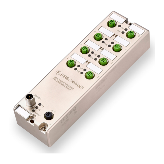
1.2.2 OCTOPUS 8TX PoE-EEC POWER Item Characteristic Slot hole for mounting on a flat surface 8 × Indicator plate 7 × 4-pin, “D”-coded M12 socket for 10/100 Mbit/s twisted pair connections with PoE support 15 × LED display elements for port status PoE status LED display element for device status M12 interface for the connection of ACA21-M12 (EEC) and ACA22-M12 (EEC) - Page 16 The device supports Power over Ethernet Plus in accordance with IEEE 802.3at (PoE+) and enables you to supply current to terminal devices such as IP phones via the twisted-pair cable. The Power over Ethernet Plus function is activated both globally and on the PoE-capable ports on delivery.
-
Page 17: Octopus 8Tx-Eec-M
1.2.3 OCTOPUS 8TX-EEC-M POWER ACA22-C Item Characteristic Slot hole for mounting on a flat surface 8 × Indicator plate 8 × 4-pin, “D”-coded M12 socket for 10/100 Mbit/s twisted pair connections 8 × LED Port status LED display element for device status M12 interface for the connection of ACA22-M12-C (EEC) or a USB adapter cable Ground connection Slot hole for mounting on a flat surface... -
Page 18: Power Supply
Power supply The supply voltage is connected by means of a 5-pin, “A”-coded M12 connector (e. g. ELWIKA 5012 PG7). You will find more information here: “Connecting the power supply and the signal contact lines” on page 32 Ethernet ports You can connect terminal devices and other segments at the ports of the device via twisted pair cables. -
Page 19: Pin Assignment Octopus 8Tx-Eec And Octopus 8Tx-Eec-M
This port supports: Autonegotiation Autopolarity Autocrossing 100 Mbit/s half-duplex mode, 100 Mbit/s full duplex mode 10 Mbit/s half-duplex mode, 10 Mbit/s full duplex mode Power over Ethernet (PoE/PoE+) Devices are supplied with PoE voltage (54 V DC SELV) using the internal power supply. -
Page 20: Display Elements
Display elements After the supply voltage is set up, the software starts and initializes itself. During this process, various LEDs light up. 1.5.1 Device state These LEDs provide information about conditions which affect the operation of the whole device. Power Figure 1: Display elements device status OCTOPUS 8TX-EEC Display Color... - Page 21 Power FAULT Figure 2: Display elements device status OCTOPUS 8TX PoE-EEC Display Color Activity Meaning Supply voltage green lights up Supply voltage is on none Supply voltage is too low Supply voltage green lights up Supply voltage is on none Supply voltage is too low FAULT PoE status lights up...
- Page 22 Power Power Status Figure 3: Display elements device status OCTOPUS 8TX-EEC-M Display Color Activity Meaning Power Supply voltage — none Supply voltages 1 and 2 are too low. yellow lights up Supply voltage 1 or 2 is on flashes 4 Software update is running.
-
Page 23: Port Status
1.5.2 Port Status These LEDs provide port-related information. Figure 4: Display elements port status OCTOPUS 8TX-EEC Display Color Activity Meaning Link state/ — none Device detects an invalid or data traffic missing link green lights up Device detects a valid link yellow flashing Device is transmitting and/or... - Page 24 Figure 5: Display elements port status OCTOPUS 8TX PoE-EEC Display Color Activity Meaning Link state/ — none Device detects an invalid or data traffic missing link green lights up Device detects a valid link yellow flashing Device is transmitting and/or receiving data green/ flashing alternately...
- Page 25 Figure 6: Display elements port status OCTOPUS 8TX-EEC-M Display Color Activity Meaning Link state/ — none Device detects an invalid or missing link data traffic green lights up Device detects a valid link flashes 1 time a Port is switched to stand-by period flashes 3 times a Port is switched off...
-
Page 26: Management Interfaces
Management interfaces 1.6.1 ACA-M12 interface This applies to the following device variants only: OCTOPUS 8TX-EEC OCTOPUS 8TX PoE-EEC This interface is a 5-pin, “A”-coded M12 socket with shielding. This interface allows you to connect the ACA21-M12 (EEC) or ACA22- M12 (EEC) storage medium. - Page 27 Function ACA22-C Data - Ground (0 V) Data + Figure 8: ACA22-C interface: Position on the device and pin assignment The interface was designed for the use with the external storage medium AutoConfiguration Adapter ACA22-M12-C (EEC). Additionally, the interface allows you to connect your device temporarily via terminal emulation or network to an external device using an adapter cable.
-
Page 28: Signal Contact
Configuration, management and checking via adapter cable You have the option to configure, manage and check your device via the interface using an adapter cable. You find detailed information in the software user documentation. You find the software user documentation as PDF files on the Internet at https://www.doc.hirschmann.com The adapter cable is available as an accessory... - Page 29 You will find detailed information on possible applications and the configuration of the signal contact in the software user documentation. You will find the software user documentation as PDF files on the Internet at https://www.doc.hirschmann.com Installation OCTOPUS 8TX-EEC Release 07 01/2021...
-
Page 30: Installation
Installation The devices have been developed for practical application in a harsh industrial environment. On delivery, the device is ready for operation. Perform the following steps to install and configure the device: Checking the package contents Installing and grounding the device ... -
Page 31: Grounding The Device
Perform the following work steps: Prepare the drill holes at the installation point. See “Dimension drawings” on page 49. Mount the device on a level surface with two M4 screws. 2.2.2 Grounding the device Requirements: Use a suitable wire diameter for the functional grounding. Hirschmann recommends a wire diameter of 0.5 mm²... -
Page 32: Connecting The Power Supply And The Signal Contact Lines
Connecting the power supply and the signal contact lines Requirements: The power supply cable is suitable for the voltage, the current and the physical load. Hirschmann recommends a conductor cross section of 0.5 mm² to 0.75 mm² (AWG20 up to AWG18). ... -
Page 33: Pin Assignment Octopus 8Tx Poe-Eec
2.3.3 Pin assignment OCTOPUS 8TX PoE-EEC M12 5-pin (“A”- Function coded) Power supply (1): +24 V DC (1) Not used Power supply (2): +24 V DC (2) Not used 2.3.4 Pin assignment OCTOPUS 8TX-EEC-M M12 5-pin (“A”- Function coded) Power supply (1): + 24/36 V DC (1) Signal contact Power supply (2): + 24/36 V DC (2) Signal contact... -
Page 34: Connecting Data Cables
Connecting data cables Note the following general recommendations for data cable connections in environments with high electrical interference levels: Keep the length of the data cables as short as possible. When using copper cables, provide a sufficient separation between the power supply cables and the data cables. -
Page 35: Configuration (Optional)
Configuration (optional) This applies to the following device variants only: OCTOPUS 8TX-EEC OCTOPUS 8TX PoE-EEC The device is immediately ready for operation with its default settings, from the factory. You have the option to change the settings according to your requirements using the ACA M12 interface. - Page 36 Perform the following work steps: Connect the storage medium to the device. Start the Switch Programming Tool. Select your device variant from the drop-down list “Device Type”. Modify the parameters in the highlighted areas according to your requirements.
- Page 37 Save the configuration file to the storage medium. Installation OCTOPUS 8TX-EEC Release 07 01/2021...
- Page 38 Disconnect the M12 USB Adapter from your PC. Disconnect the storage medium from the M12 USB Adapter. Transfer the configuration data to your device by following these steps: Verify that the device is switched off. Connect the storage medium to the device. ...
- Page 39 Parameter Values Default values Comment global Aging time Aging time in s 300 s Value range 0 ... 1048575 QoS 802.1p mapping VLAN Priority 0 ... 7 VLAN Priority Traffic Class Traffic Class 0 ... 3 QoS DSCP mapping DSCP value 0 ... 63 See table 2 on page 40.
- Page 40 Parameter Values Default values Comment per PoE port PoE enable enabled / disabled enabled PoE priority low, high, critical critical is highest (PoE allowed classes) class 0, 1, 2, 3, 4 class 0, 1, 2, all combinations configurable 3, 4 Table 1: Configuration parameters d2/d1 0...
-
Page 41: Configuration Readout
2.6.1 Configuration readout Perform the following steps to start up the device: Connect the storage medium to your PC using the M12 USB Adapter. Create a text file in the root directory of the storage medium. Rename the text file to “ShowRunningConfiguration.txt”. ... -
Page 42: Making Basic Settings
Making basic settings This applies to the following device variants only: OCTOPUS 8TX-EEC-M Note: 2 or more devices configured with the same IP address can cause unpredictable operation of your network. Install and maintain a process that assigns a unique IP address to every device in the network. -
Page 43: First Login (Password Change)
Log on to the device again with your new password. Note: If you lost your password, then use the System Monitor to reset the password. For further information see: https://hirschmann-support.belden.com/en/kb/required-password-change- new-procedure-for-first-time-login Installation OCTOPUS 8TX-EEC Release 07 01/2021... -
Page 44: Monitoring The Ambient Air Temperature
Monitoring the ambient air temperature Operate the device below the specified maximum ambient air temperature exclusively. See “General technical data” on page 47. The ambient air temperature is the temperature of the air at a distance of 2 in (5 cm) from the device. It depends on the installation conditions of the device, for example the distance from other devices or other objects, and the output of neighboring devices. -
Page 45: Maintenance And Service
Maintenance and service When designing this device, Hirschmann largely avoided using high-wear parts. The parts subject to wear and tear are dimensioned to last longer than the lifetime of the product when it is operated normally. Operate this device according to the specifications. ... -
Page 46: Disassembly
Disassembly Perform the following work steps: Disable the supply voltage. Disconnect the data cables. Disconnect the grounding. Unmount the device. Installation OCTOPUS 8TX-EEC Release 07 01/2021... -
Page 47: Technical Data
Technical data General technical data Dimensions OCTOPUS 8TX-EEC 2.40 in × 1.22 in × 7.91 in W × D × H (61 mm × 31 mm × 201 mm) OCTOPUS 8TX PoE-EEC 2.40 in × 1.81 in × 7.91 in (61 mm ×... - Page 48 Power supply Rated voltage DC: 24/36 V DC OCTOPUS 8TX-EEC-M Voltage range DC incl. 16.8 V DC ... 45 V DC maximum tolerances: Connection type 5-pin, “A”-coded M12 connector Power loss buffer >10 ms Back-up fuse for each voltage Nominal rating: 2 A ...
-
Page 49: Dimension Drawings
Dimension drawings inch 60,7 20,4 TP - Ports Function OCTOPUS 8TX-EEC IP67 ETHERNET Switch Pin Function N.C. POWER N.C. POWER 0.71 0.24 0.51 Figure 11: OCTOPUS 8TX-EEC Installation OCTOPUS 8TX-EEC Release 07 01/2021... - Page 50 inch 60,7 36,4 TP - Ports Function OCTOPUS 8TX-PoE-EEC IP67 ETHERNET Switch Pin Function N.C. POWER N.C. POWER FAULT 46,1 0.24 Figure 12: OCTOPUS 8TX PoE-EEC Installation OCTOPUS 8TX-EEC Release 07 01/2021...
- Page 51 inch 60,7 36,4 TP - Ports Function OCTOPUS 8TX-EEC-M-2x IP67 ETHERNET Switch MAC: XXXXXXXXXXX Pin Function Pin Function POWER ACA22-C FAULT Power Status ACA22-C POWER 46,1 0.24 Figure 13: OCTOPUS 8TX-EEC-M Installation OCTOPUS 8TX-EEC Release 07 01/2021...
-
Page 52: Emc And Immunity
EMC and immunity EMC interference emission Radiated emission EN 55032 Class A FCC 47 CFR Part 15 Class A EN 61000-6-4 Fulfilled Conducted emission EN 55032 Supply connection Class A FCC 47 CFR Part 15 Supply connection Class A EN 61000-6-4 Supply connection Fulfilled EN 55032... -
Page 53: Power Consumption/Power Output
Power consumption/power output Name Maximum power consumption power output OCTOPUS 8TX-EEC 4.2 W 14.3 Btu (IT)/h OCTOPUS 8TX PoE-EEC 44 W 47.8 Btu (IT)/h OCTOPUS 8TX-EEC-M 20.0 Btu (IT)/h Signal contact This applies to the following device variants only: OCTOPUS 8TX-EEC-M Signal contact Connection type... -
Page 54: Scope Of Delivery, Order Numbers And Accessories
Scope of delivery, order numbers and accessories Scope of delivery Note: The connector ELWIKA 5012 PG7 (933 175-100) supports a temperature range from -13 °F to +158 °F (-25 °C to +70 °C). It may thus limit the application range of the overall system. You can obtain special sockets for the total temperature range and with the degree of protection IP65/67 and on request. - Page 55 Name Order number Protection screw for M12 socket, plastic, IP65/67 (25 pieces) 942 057-002 Protection screw for M12 socket, metal, IP65/67 (25 pieces) 942 057-001 Connector ELWIKA 5012 PG7 933 175-100 (5-pin M12 socket for voltage supply) Transition M12 “D”-coded to RJ45 934 498-001 Connection cable with M12 connectors, 4-pin, “D”-coded Length 2 m...
-
Page 56: Underlying Technical Standards
Underlying technical standards Name FCC 47 CFR Part 15 Code of Federal Regulations UL/IEC 61010-2-201 Safety requirements for electrical equipment for measurement, control and laboratory use - Part 2-201: Particular requirements for control equipment. ISA-12.12.01 Nonincendive Electrical Equipment for Use in Class I and II, Division 2 and Class III, Divisions 1 and 2 Hazardous (Classified) Locations. -
Page 57: A Further Support
A list of local telephone numbers and email addresses for technical support directly from Hirschmann is available at https:// hirschmann-support.belden.com. This site also includes a free of charge knowledge base and a software download section. Hirschmann Competence Center The Hirschmann Competence Center is ahead of its competitors on three counts with its complete range of innovative services: ... -
Page 58: B Open Source Software Used In The Product
Open Source Software used in the product The product contains, among other things, Open Source Software files, as defined below, developed by third parties and licensed under an Open Source Software license. These Open Source Software files are protected by copyright. Your right to use the Open Source Software is governed by the relevant applicable Open Source Software license conditions Your compliance with those license conditions will entitle you to use the Open... - Page 59 Hirschmann Automation and Control GmbH specifically disclaims any warranty for defects caused by altering any Open Source Software or the product's configuration. Any warranty claims against Hirschmann Automation and Control GmbH in the event that the Open Source Software contained in this product infringes the intellectual property rights of a third party are excluded.
- Page 60 THIS SOFTWARE IS PROVIDED BY ATMEL "AS IS" AND ANY EXPRESS OR IMPLIED WARRANTIES, INCLUDING, BUT NOT LIMITED TO, THE IMPLIED WARRANTIES OF MERCHANTABILITY, FITNESS FOR A PARTICULAR PURPOSE AND NON-INFRINGEMENT ARE EXPRESSLY AND SPECIFICALLY DISCLAIMED. IN NO EVENT SHALL ATMEL BE LIABLE OR ANY DIRECT, INDIRECT, INCIDENTAL, SPECIAL, EXEMPLARY, OR CONSEQUENTIAL DAMAGES (INCLUDING, BUT NOT LIMITED TO, PROCUREMENT OF SUBSTITUTE GOODS OR SERVICES;...
- Page 61 END USER LICENCE AGREEMENT FOR THE CORTEX MICROCONTROLLER SOFTWARE INTERFACE STANDARD (CMSIS) SPECIFICATION AND SOFTWARE THIS END USER LICENCE AGREEMENT (“LICENCE”) IS A LEGAL AGREEMENT BETWEEN YOU (EITHER A SINGLE INDIVIDUAL, OR SINGLE LEGAL ENTITY) AND ARM LIMITED (“ARM”) FOR THE USE OF THE CMSIS SPECIFICATION, EXAMPLE CODE, DSP LIBRARY SPECIFICATION AND DSP LIBRARY IMPLEMENTATION AS SUCH TERMS ARE DEFINED BELOW (COLLECTIVELY, THE “ARM...
- Page 62 “DSP Library Specification” means the DSP library documentation and C programming language file defining the application programming interface of the DSP Library Implementation. Notwithstanding the foregoing, “DSP Library Specification” shall not include (i) the implementation of other published specifications referenced in the DSP Library Specification; (ii) any enabling technologies that may be necessary to make or use any product or portion thereof that complies with the DSP Library Specification, but are not themselves expressly set forth in the DSP Library Specification (e.g.
- Page 63 (iii) use, copy, modify and sublicense the Example Code solely for the purpose of developing, having developed, manufacturing, having manufactured, offering to sell, selling, supplying or otherwise distributing products that comply with either or both the CMSIS Specification and the DSP Library Specification, provided that you preserve any copyright notices which are included with, or in, the Example Code and that you do not use ARM's name, logo or trademarks to market such products;...
- Page 64 COPYRIGHT AND RESERVATION OF RIGHTS: The ARM Deliverables are owned by ARM or its licensors and are protected by copyright and other intellectual property laws and international treaties. The ARM Deliverables are licensed not sold. Except as expressly licensed herein, you acquire no right, title or interest in the ARM Deliverables or any intellectual property therein.
- Page 65 7.3 This Licence shall immediately terminate and shall be unavailable to you if you or any party affiliated to you asserts any patents against ARM, ARM affiliates, third parties who have a valid licence from ARM for the ARM Deliverables, or any customers or distributors of any of them based upon a claim that your (or your affiliate) patent is Necessary to implement the CMSIS Specification or DSP Library Specification.
Need help?
Do you have a question about the Hirschmann OCTOPUS 8TX PoE-EEC and is the answer not in the manual?
Questions and answers