Icom IC-78 Instruction Manual
Hide thumbs
Also See for IC-78:
- Service manualvice man (56 pages) ,
- Instruction manual (48 pages) ,
- Service manual (7 pages)
Table of Contents
Advertisement
Quick Links
INSTRUCTION MANUAL
HF TRANSCEIVER
i78
This device complies with Part 15 of the FCC rules. Operation is sub-
ject to the following two conditions: (1) This device may not cause
harmful interference, and (2) this device must accept any interference
received, including interference that may cause undesired operation.
Advertisement
Table of Contents

Subscribe to Our Youtube Channel
Related Manuals for Icom IC-78


Summary of Contents for Icom IC-78
- Page 1 INSTRUCTION MANUAL HF TRANSCEIVER This device complies with Part 15 of the FCC rules. Operation is sub- ject to the following two conditions: (1) This device may not cause harmful interference, and (2) this device must accept any interference received, including interference that may cause undesired operation.
-
Page 2: Important
DO NOT operate the transceiver near unshielded Icom, Icom Inc. and Icom logo are registered trade- electrical blasting caps or in an explosive atmosphere. marks of Icom Incorporated (Japan) in Japan, the Unit- ed States, United Kingdom, Germany, France, Spain,... -
Page 3: Table Of Contents
Use only supplied or optional Icom microphones. n Troubleshooting ..........38 Other manufacturer’s microphones have different n Fuse replacement ..........39 pin assignments, and connecting to the IC-78 may n Resetting the CPU ........... 39 damage the transceiver. 8 REMOTE JACK INFORMATION ....40– 41 n CI-V remote control .......... -
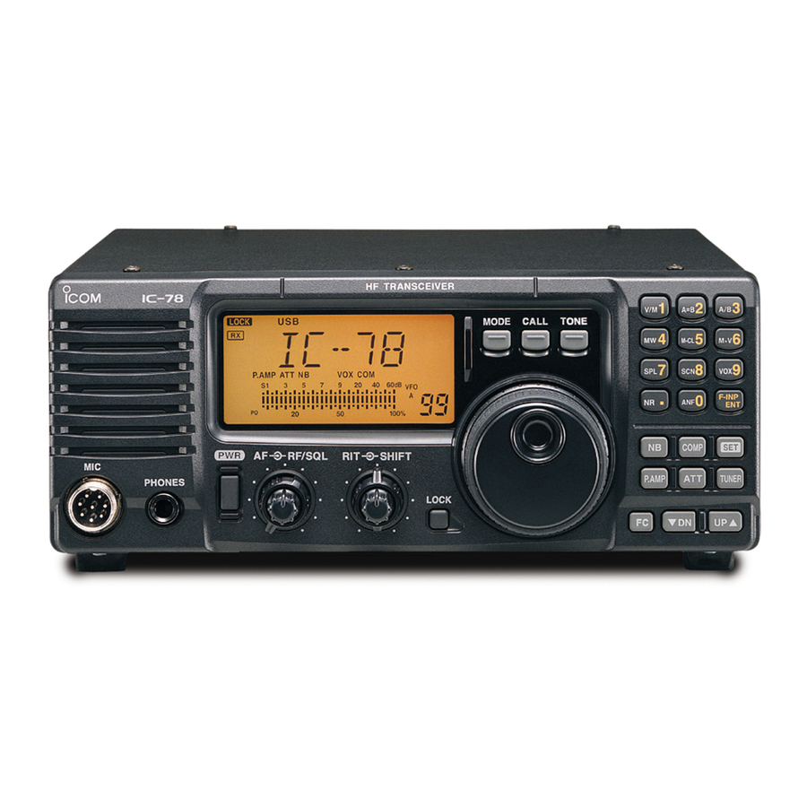
Page 4: Panel Description
PANEL DESCRIPTION Front panel Speaker Function Display q POWER SWITCH [PWR] u IF SHIFT CONTROLS [SHIFT] ➥ Push to turn ON the power. (outer control, • First, confirm the DC power supply is ON. Shifts the center frequency of the receiver’s IF ➥... - Page 5 PANEL DESCRIPTION !3 ATTENUATOR SWITCH [ATT] !9 TONE SWITCH [TONE] Push to turn the 20 dB attenuator function ON or * This key action may differ, depending on the OFF. transceiver version. ➥ Selects the Call channel and emits a distress !4 TUNER SWITCH [TUNER] alarm tone from the speaker.
-
Page 6: Function Display
PANEL DESCRIPTION Function display q LOCK ICON i VFO/MEMORY ICON ➥ “MEMO” is displayed during regular operation. Displays when the dial lock function is in use. * This icon is displayed only some versions. w RECEIVE ICON ➥ “VFO” is displayed during VFO operation. Displays while receiving a signal or when the squelch is open. -
Page 7: Rear Panel
TUNER CONTROL SOCKET [TUNER] Accepts the control cable from an optional antenna i ALC INPUT JACK [ALC] tuner. Connects to the ALC output jack of a non-Icom lin- ear amplifier. r REMOTE JACK [REMOTE] For use with a personal computer for remote opera- o SEND CONTROL JACK [SEND] tion of the transceiver’s functions, and for data clon-... - Page 8 When the diode is added, a switching delay of the relay may occur. Be sure to check its switching action before operation. [Example] Switching diode To a non-Icom socket linear amplifier eSEND Relay i13.8V...
-
Page 9: Microphone (Hm-36)
8 V regulator. DC voltage is w PTT SWITCH also applied to pin 1 for microphone operation. Use Hold down to transmit, release to receive. caution when using a non-Icom microphone. • HM-36 SCHEMATIC DIAGRAM Microphone Microphone Plug 22 kø... -
Page 10: Installation And Connections
In this case, an antenna tuner is useful to match the transceiver and antenna. Low SWR allows near full power for transmitting even when using the antenna tuner. The IC-78 has an SWR meter to continuously monitor the antenna SWR. Grounding... -
Page 11: Required Connections
INSTALLATION AND CONNECTIONS Required connections • Front panel MICROPHONES (p. 43) SM-30 SM-50 HM-36 • Rear panel ANTENNA DC POWER SUPPLY [Example]: 1.8–30 MHz bands PS-126 AH-710 GROUND (p. 7) CW KEY Use the heaviest gauge wire or strap available and make the connection as short as possible. -
Page 12: Advanced Connections
AT-130, or AH-740 with AH-4 (p. 43) (p. 43) AH-2b or long wire ANTENNA Connects a linear amplifier, etc. ACC SOCKETS (p. 5) EXTERNAL SPEAKER (p. 43) [SEND], [ALC] Used for connecting a non-Icom linear ampli- fier. SP-23 (Option) -
Page 13: Connecting The Power Supply
Use an optional PS-126 DC POWER SUPPLY w • Output voltage of the power source is 12 to 15 V operating the IC-78 with AC power. Refer to the dia- grams below. when you use a non-Icom power supply. • DC power cable polarity is correct. -
Page 14: External Antenna Tuners
INSTALLATION AND CONNECTIONS External antenna tuners CONNECTING AN ANTENNA TUNER Long wire or optional AH-2b Coaxial cable (from the tuner) Control cable IC-78 AT-130/AH-4 Ground Ground CONNECTING THE AH-740 Coaxial cable and control cable connections Coaxial cable (from the AH-740) -
Page 15: Operation
OPERATION Selecting a channel The transceiver has 99 memory channels. However, the number of channels can be restricted in the Initial Set mode 30) depending on your needs. A total of 3 ways of channel selections are available to suit your operating style. -
Page 16: Frequency Indication
OPERATION Frequency indication Push [FC] to display the channel name or channel Push frequency. D Transmit frequency indication Push [TXF] to display the transmit frequency instead of the channel name or operating frequency. Channel displayed When the transmit frequency is displayed, “ ”... -
Page 17: Basic Voice Receive And Transmit
Channel Selector, [UP p] or [q DN], or 10-key pad. i Release [PTT] to return to receive. • The S-meter shows signal strength when signal is received. Mode selection The following modes are available in the IC-78: OPERATING MODE SELECTION SSB (LSB/USB), CW, CW REV (CW reverse), RTTY, MODE Push RTTY REV (RTTY reverse) and AM. -
Page 18: Functions For Transmit
OPERATION Functions for transmit Output power and microphone gain • Setting output power • Setting microphone gain q Hold down [SET] for 1 second to select the Quick Microphone gain must be adjusted properly so that Set mode. your signal does not distort when transmitted. w Push [UP p] or [q DN] to select “RF POWER”. - Page 19 OPERATION Microphone compressor IC-78 has a built-in, low distortion Mic compressor cir- e Confirm the ALC level. cuit. This circuit increases your average talk power in • Push [SET] to select the ALC meter. SSB mode and is especially useful when the receiv- •...
- Page 20 • 13: AT-130 is selected. AT-130 or AH-4 y Hold down [PWR] for 1 second to turn power The AT-130 or AH-4 matches the IC-78 to a long OFF. wire antenna more than 7 m/23 ft long (3.5 MHz and u Push [PWR] to turn power ON again.
-
Page 21: Functions For Receive
OPERATION Functions for receive RIT function The RIT (Receive Incremental Tuning) function com- w To cancel the RIT function, RIT off position pensates for off-frequencies of communicating sta- rotate the RIT control to the tions. The function shifts the receive frequency up to center position. - Page 22 OPERATION Meter peak hold The meter peak hold function freezes the highest dis- Initial reception of a signal played bar segment in any meter function for about results in an S-meter reading 0.5 seconds so that you can more easily read the of 40 dB.
-
Page 23: Filter Selection
OPERATION Filter selection • Optional filter variations The filter selection changes the IF passband width as shown in the table to the right. Name Band width Mode The filter selection is for temporal setting. FL-52A † 500 Hz/–6 dB CW/RTTY-N FL-53A †... -
Page 24: Filter Setting
OPERATION Filter setting When an optional filter is installed, set the optional fil- ters in the Initial Set mode. Optional filters are not se- lected by default. Optional filter setting q While holding down [SET], push [PWR] to enter the Initial Set mode. w Push [UP p] or [q DN] several times until “FIL”... -
Page 25: Functions For Cw
OPERATION Function for CW Connection for CW Initial Set mode setting (p. 31) 9 10 11 12 1 2 3 4 : normal [ELEC KEY] For no break-in operation: Paddle Connect an external switch such as [ACC] a foot switch; or use the RTTY : reverse SEND terminal for all bands. - Page 26 CW mode (USB side) CW REV mode (LSB side) Electronic CW keyer The IC-78 has an electronic keyer. Both keying speed KEYING WEIGHT EXAMPLE: morse code “K” and weight (the ratio of dot : space : dash) can be set in the Quick Set mode.
-
Page 27: Functions For Rtty
OPERATION Function for RTTY Connection for RTTY (FSK) Rear panel TU or TNC 2-conductor ⁄ ” plug Use either the ACC or one of the two ⁄ ” plugs. Rear panel view SQL* AF out 9 10 11 12 SEND 5 6 7 8 Connect SQL line when required. - Page 28 OPERATION RTTY (FSK) operation q Connect a terminal unit as on page RTTY mode w Select RTTY (or RTTY-R) mode with [MODE]. is selected. e Select the desired FSK tone and shift frequencies as below. r Set the desired frequency with the Channel Se- lector.
-
Page 29: Channel Name Entry
OPERATION Channel name entry You can enter a channel name of up to 8 characters for each Memory channel. This provides easy recogni- tion of channel use or the station name. q Select the desired channel by pushing [UP p] •... -
Page 30: Set Mode
SET MODE General The Set modes are used for setting infrequent- ly changed values or options. The IC-78 has 2 sep- arate set modes, the Quick Set mode and the Initial Set mode. [DIAL] Quick Set mode operation q While power is ON, hold down [SET] for 1 second. -
Page 31: Quick Set Mode Items
SET MODE Quick Set mode items • RF power Adjusts the RF output power. The RF output power can be adjusted from L, 1 to 99 and H by indication, however, it can be adjusted continuously. •The default is H (maximum power). Note that while adjusting the output power, the power meter is displayed auto- matically. - Page 32 SET MODE — (continued) Quick Set mode items • BK-IN Selects the break-in type for CW operation. There are three selectable values: oF: No break-in operation (default). SE: Semi break-in operation. FL: Full break-in operation • BK-IN delay Adjusts the break-in delay time for the CW semi break-in operation. The delay time is selectable from 2.0 to 13 (dots).
-
Page 33: Initial Set Mode Items
SET MODE Initial Set mode items • RF/SQL control action Selects the [RF/SQL] control action from RF/squelch, automatic (acts as a squelch in AM modes and an RF in SSB/CW/RTTY modes), or the squelch only. (See page The default is Sq (squelch). •... - Page 34 The IC-78’s address is 62. When 2 or more IC-78s are connected to an optional CT-17 V LEVEL CONVERT , rotate the main dial to select a different address for each IC-78 to between 01 and 7F (Hexadecimal). The default is 62.
- Page 35 SET MODE • Optional filter selection When an optional IF filer is installed, this selection is necessary, otherwise the optional filter cannot be selected. Select FL-52A, † FL-53A, † FL-96, † FL-222, FL- 257 or none (default). See page 21 for usable filters for each mode and see page for filter installation.
-
Page 36: Extra Features
EXTRA FEATURES Introduction Extra features, explained in this section, are available only on some versions of the IC-78. Therefore, the instructions in this section may not be necessary for some versions. VFO operation Entering VFO mode To enter the VFO mode, hold down [FC] for 1 sec- ond. - Page 37 EXTRA FEATURES Channel setting Both the transmit and receive, frequencies in the op- erating channel can be entered in the VFO mode. • Simplex channel programming q Hold down [FC] for 1 second to enter VFO mode. w Push [UP p] or [q DN] to select the desired chan- nel.
-
Page 38: N 2-Tone Alarm Operation
EXTRA FEATURES Clearing a Memory channel If there are unnecessary channels, they can be Note: Blank channels cannot be selected by push- cleared. The cleared channels are skipped in the ing [UPp] or [q DN], and Channel Selector. It channel mode operation, can be selected with the Keypad. -
Page 39: Option Installation
CAUTION: DISCONNECT the DC power cable from the IC-78 before performing any work on the transceiver. Otherwise, there is danger of electric shock and/or equipment damage. q Remove the 5 screws from the top of the transceiv- er and 4 screws from the sides, then lift up the top cover. -
Page 40: Cr-338 High Stability Crystal Unit
• Connect the frequency counter to P 2 (PLL unit). u Return the bottom cover to its original position. Optional IF filters Several IF filters are available for the IC-78. You can e Install the de- Optional IF filter install one 455 kHz IF filter. Choose the appropriate fil- sired 455 kHz ter for your operating needs. -
Page 41: Maintenance
If you are not able to locate the cause of the problem, The following chart is designed to help you correct or solve it through the use of this chart, contact your problems which are not equipment malfunctions. nearest Icom dealer or Service Center. PROBLEM POSSIBLE CAUSE SOLUTION REF. -
Page 42: Fuse Replacement
• Circuitry fuse ……………………………… FGB 4 A CIRCUITRY FUSE REPLACEMENT The 13.8 V DC from the DC power source is applied to all units in the IC-78 through the circuitry fuse. This FGB 4 A fuse is in the PA unit. -
Page 43: Remote Jack Information
9–15 V DC cations Interface-V (CI-V) controls the following func- tions of the transceiver. Up to 4 Icom CI-V transceivers or receivers can be connected to a personal computer equipped with an ct-17 RS-232C port, or through an RS-232 to USB Serial adapter. -
Page 44: Data Cloning Between Transceivers
The IC-78’s data (Entered frequencies, channel names, both the Quick and Initial Set mode values, and so on.) can be copied to another IC-78. This function is useful when exactly the same settings of the IC-78s are required. • Cloning operation q Turn power OFF. -
Page 45: Specifications
SPECIFICATIONS GENERAL TRANSMITTER • Frequency range: • Modulation system: 0.030000–29.999999 MHz* Balanced modulation 1.600000–29.999999 MHz* Low level modulation • Output power: Guaranteed range: 0.5–29.999999 MHz SSB, CW, RTTY 2–100 W Not guaranteed for some frequency bands • Mode: USB, LSB, CW, RTTY, AM 2–35 W •... -
Page 46: Options
OPTIONS AH-740 AT-130/E AH-4 AUTOMATIC ANTENNA TUNER AUTOMATIC TUNING ANTENNA AUTOMATIC ANTENNA TUNER High performance, automatic high-speed tuning antenna. • Frequency coverage With 1.54 m whip antenna: 2.5 MHz–29.9999 MHz With AH-5NV (NVIS kit): 2.2 MHz–29.9999 MHz Specially designed to tune a long wire antenna for portable or mobile HF op- eration. - Page 47 OPTIONS FL-222 and FL-257 CR-338 MB-23 CARRYING HANDLE FILTERS HIGH STABILITY CRYSTAL UNIT • FL-222: 1.8 kHz/–6 dB (SSB narrow) • FL-257: 3.3 kHz/–6 dB (SSB wide) Contains a temperature-compensating Carrying handle, convenient for oven heater and crystal unit for portable operation.
- Page 48 A-5658H-1EX-r Printed in Japan © 2000–2015 Icom Inc. 1-1-32 Kamiminami, Hirano-ku, Osaka 547-0003, Japan Printed on recycled paper with soy ink.
Need help?
Do you have a question about the IC-78 and is the answer not in the manual?
Questions and answers