Icom IC-7800 Manual
Hide thumbs
Also See for IC-7800:
- Service manual addendum (555 pages) ,
- Instruction manual (230 pages) ,
- Service manual (216 pages)
Table of Contents
Advertisement
Quick Links
2
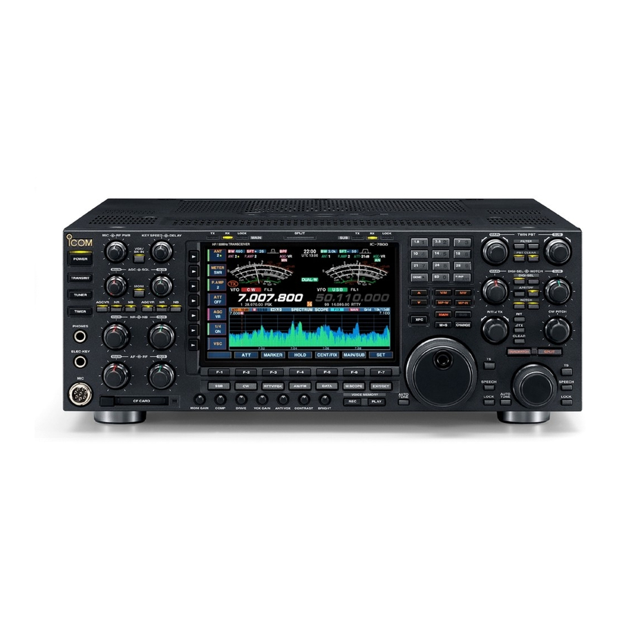
INSTALLATION AND CONNECTIONS
■ Required connections
D Front panel
CW key
A straight key can be used when the
internal electronic keyer is turned OFF in
keyer set mode. (p. 4-12)
Microphones (p. 2-9)
Optional
SM-20
D Rear panel
Antenna 1, 2, 3, 4 (p. 2-3)
[Example]: ANT1 for 1.8–18 MHz bands, ANT 2 for 21–28 bands
ANT3 for 50 MHz band, ANT 4 for receive antenna
EXT-DISPLAY
Ground
(p. 2-3)
Optional
HM-36
ANT 1
ANT 2
REF I/O
S/P DIF
10MHz
KEY BOARD
RS-232C
REMOTE
OUT
IN
-10dBm
Use the heaviest gauge
wire or strap available and
make the connection as
short as possible.
Grounding prevents elec-
trical shocks, TVI and oth-
er problems.
OUT
ANT 3
ANT 4
GND
DC OUT
EXT
ALC
15V
MAX1A
METER
KEYPAD
KEY
RELAY
ALC
ADJ
Straight key
2-4
A jumper cable is
connected.
IN
X-VERTER
OUT
IN
RX ANT
RX ANT
B
A
I
AC
B
A
EXT - SP
ACC 2
ACC 1
ACC 2
ACC 1
SUB
MAIN
AC outlet
R WARNING:
Use the supplied
AC power cable
only.
Advertisement
Chapters
Table of Contents

Related Manuals for Icom IC-7800


Summary of Contents for Icom IC-7800
- Page 1 INSTALLATION AND CONNECTIONS ■ Required connections D Front panel CW key A straight key can be used when the internal electronic keyer is turned OFF in keyer set mode. (p. 4-12) Microphones (p. 2-9) Optional Optional SM-20 HM-36 D Rear panel Antenna 1, 2, 3, 4 (p.
- Page 2 (pgs.2-8, 2-10) Used for computer control and transceive operation. for V/UHF band use. The optional CT-17 is required when con- External speaker (p. 15-4) necting a PC to [REMOTE]. [RELAY], [ALC] (p.2-7) Used for connecting a non-Icom linear amplifier. SP-20 (option)
- Page 3 INSTALLATION AND CONNECTIONS D Rear panel— 2 External Display Keyboard Connects an USB type Connects a monitor dis- PC keyboard directly for play (at least 800×600 [DC OUT] RTTY/PSK31 operation, resolution) directory. Outputs regulated 14 V as well as other text edit Video output signal can (approx.) DC for external operation.
- Page 4 16 V/0.5 A with initial setting, and 250 V/200 mA with “MOS-FET” setting (see p. 12-9 for details). Use an external relay unit when your non-Icom linear ampli- RF OUTPUT RF INPUT fier require the control level that higher voltage SEND and/or larger current capacity.
- Page 5 INSTALLATION AND CONNECTIONS ■ Transverter jack information When 2 to 13.8 V is applied to pin 6 of [ACC 2], the [X- VERTER] connector is activated for transverter opera- tion and the antenna connectors do not receive or transmit any signals. (p. 4-6) While receiving, [X-VERTER] connector can be acti- vated as an input terminal from an external transverter.
- Page 6 DO NOT short pin 2 to ground as this can damage the internal 8 V regulator. NOTE: DC voltage is applied to pin 1 for micro- phone operation. Take care when using a non-Icom microphone. ■ Microphones (options) q UP/DOWN SWITCHES [UP]/[DN]...
- Page 7 INSTALLATION AND CONNECTIONS ■ Accessory connector information ACC 1 PIN No. NAME DESCRIPTION SPECIFICATIONS “High” level : More than 2.4 V RTTY Controls RTTY keying “Low” level : Less than 0.6 V Output current : Less than 2 mA GND Connects to ground. Connected in parallel with ACC 2 pin 2.
-
Page 8: Table Of Contents
BASIC OPERATIONS Section ■ When first applying power (CPU resetting) ………………………… 3-2 ■ Initial settings …………………………………………………………… 3-2 ■ Main/Sub band selection ……………………………………………… 3-3 ■ Selecting VFO/memory mode ………………………………………… 3-3 ■ Selecting an operating band …………………………………………… 3-4 D Using the band stacking registers ………………………………… 3-4 ■... -
Page 9: Basic Operations
BASIC OPERATIONS ■ When first applying power (CPU resetting) Before first applying power, make sure all connections required for your system are complete by referring to Section 2. Then, reset the transceiver using the follow- ing procedure. Resetting CLEARS all programmed contents in memory channels and returns programmed values in set mode to default values. -
Page 10: Main/Sub Band Selection
BASIC OPERATIONS ■ Main/Sub band selection The IC-7800 has 2 bands, main and sub bands. The main band is displayed on the left hand side, and the sub band is displayed on the right hand side of the LCD. Some functions can only be accessed to the se- lected band and the transmission is only permitted for the main band (except the split frequency operation). -
Page 11: Selecting An Operating Band
BASIC OPERATIONS ■ Selecting an operating band The triple band stacking register provides 3 memories Band keys in one band. 3 sets of a frequency and operating mode on each band are automatically stored when used. If a band key is pushed once, the frequency and oper- ating mode last used are called up. -
Page 12: Frequency Setting
BASIC OPERATIONS ■ Frequency setting The transceiver has several tuning methods for conve- nient frequency tuning. D Tuning with the main dial q Push the desired band key on the keypad 1–3 Band keys times. • 3 different frequencies can be selected on each band with the band key. -
Page 13: D Quick Tuning Step
BASIC OPERATIONS D Quick tuning step The operating frequency can be changed in kHz steps (0.1, 1, 5, 9, 10, 12.5, 20 or 25 kHz selectable) for quick tuning. q Push [TS] to turn the quick tuning function ON. • “Z” appears when the quick tuning function ON. w Rotate the main dial to change the frequency in pro- grammed kHz steps. -
Page 14: D Selecting 1 Hz Step
BASIC OPERATIONS D Selecting 1 Hz step The minimum tuning step of 1 Hz can be used for fine tuning. q Push [TS] to turn the quick tuning function OFF. w Push [TS] for 1 sec. to turn the 1 Hz tuning step ON and OFF. -
Page 15: Operating Mode Selection
CW reverse (CW-R), RTTY, RTTY reverse (RTTY-R), PSK, PSK reverse (PSK-R), AM, AM data, FM and FM data modes are available in the IC-7800. Select the desired operation mode as follows. To select a mode of operation, push the desired mode switch momentarily. -
Page 16: Volume Setting
BASIC OPERATIONS ■ Volume setting ➥ Rotate [AF] control clockwise to increase; counter- clockwise to decrease the audio output level. • Set a suitable audio level. [AF] for main [AF] for sub Audio output increases Audio output decreases ■ RF gain adjustment ➥... -
Page 17: Meter Indication Selection
Indicates the drain’s terminal voltage of the final FETs. D Multi-function digital meter The IC-7800 can display the multi-function digital meter in the LCD display, which displays all transmit meters simultaneously. q Push [METER] for 1 sec. to turn the multi-function “P-HOLD”... -
Page 18: D Meter Type Selection
BASIC OPERATIONS D Meter type selection Total of 3 meter types are available in the IC-7800— Standard, Edgewise and Bar meters. Follow the instructions below for the meter type selec- tion. q Push [EXIT/SET] several times to return to normal screen, if necessary. -
Page 19: Basic Transmit Operation
BASIC OPERATIONS ■ Basic transmit operation Before transmitting, monitor your selected oper- ating frequency to make sure transmitting won’t cause interference to other stations on the same frequency. It’s good Amateur practice to listen first, and then, even if nothing is heard, ask “is the frequency in use”... -
Page 20: D Drive Gain Adjustment
BASIC OPERATIONS D Drive gain adjustment The drive gain can be activated for the all modes ex- cept SSB without speech compressor to adjust the am- plifying gain at the drive stage. Before transmitting, monitor your selected operating [METER] [DRIVE] frequency to make sure transmitting won’t cause inter- ference to other stations on the same frequency. - Page 21 RECEIVE AND TRANSMIT Section ■ Operating SSB ………………………………………………………… 4-2 D Convenient functions for receive ……………………………………4-2 D Convenient functions for transmit ……………………………………4-3 D About 5 MHz band operation (USA version only) …………………4-3 ■ Operating CW …………………………………………………………… 4-4 D Convenient functions for receive ……………………………………4-4 D Convenient functions for transmit ……………………………………4-5 D About CW reverse mode ……………………………………………4-5 D About CW pitch control ………………………………………………4-5...
-
Page 22: Receive And Transmit
RECEIVE AND TRANSMIT ■ Operating SSB q Push a band key to select the desired band. [MIC] [TX] indicator [RX] indicator Band keys w Push [SSB] to select LSB or USB. • “USB” or “LSB” appears. • Below 10 MHz LSB is automatically selected; above 10 MHz USB is automatically selected. -
Page 23: D Convenient Functions For Transmit
FCC, show the center frequency of their To assist you in operating the 5 MHz band correctly passband. However, the IC-7800 displays carrier within the rules specified by the FCC, transmission point frequency, so set 1.5 kHz below from FCC is impossible on any 5 MHz band frequency other channel center frequency. -
Page 24: Operating Cw
RECEIVE AND TRANSMIT ■ Operating CW q Push a band key to select the desired band. [TX] indicator w Push [CW] to select CW. [KEY SPEED] [RX] indicator Band keys • After CW mode is selected, push [CW] to toggle be- tween CW and CW-R modes. -
Page 25: D Convenient Functions For Transmit
RECEIVE AND TRANSMIT D Convenient functions for transmit • Break-in function (p. 6-3) ➥ Push [VOX/BK-IN] several times to select the break-in OFF, semi break-in and full break-in. • “BK IN” or “F-BK IN” appears when the semi break-in or full break-in function is set to ON, respectively. D About CW reverse mode CW-R (CW Reverse) mode receives CW signals with a reverse side CW carrier point like that of LSB and USB... -
Page 26: D Apf (Audio Peak Filter) Operation
D About 137 kHz band operation (Europe, UK, Italy, Spain, France versions only) 137 kHz band, within 135.7 kHz to 137.8 kHz range, operation in CW mode is optionally available with the IC-7800. The RF signal from [X-VERTER] is used for the 137 kHz band operation, and an external amplifier unit is necessary. -
Page 27: Electronic Keyer Functions
RECEIVE AND TRANSMIT ■ Electronic keyer functions The IC-7800 has a number of convenient functions for the electronic keyer that can be accessed from the memory keyer menu. q During CW mode, push [EXIT/SET] several times to normal screen, if necessary.
Need help?
Do you have a question about the IC-7800 and is the answer not in the manual?
Questions and answers