Table of Contents
Advertisement
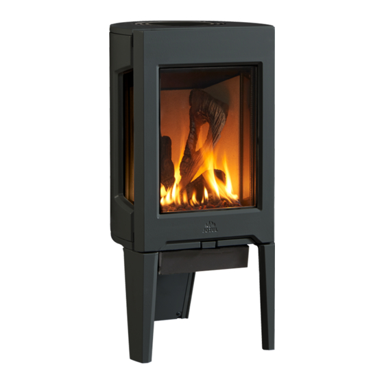
Jøtul GF 160 DV IPI
Direct Vent Gas Stove
Installation and
Operation Instructions
Conforms to ANSI Z21.88-2016 • CSA 2.33-2016
and CAN/CGA 2.17-M91
INSTALLER: Leave this manual with the appliance.
OWNER: Retain this manual for future reference.
WARNING: If the information in these
instructions is not followed exactly, a fire
or explosion may result causing property
damage, personal injury or loss of life.
– Do not store or use gasoline or other
flammable vapors and liquids in the
vicinity of this or any other appliance.
– WHAT TO DO IF YOU SMELL GAS
• Do not try to light any appliance.
• Do not touch any electrical switch; do
not use any phone in your building.
• Leave the building immediately.
• Immediately call your gas supplier
from a neighbor's phone. Follow the gas
supplier's instructions.
• If you cannot reach your gas supplier, call
the fire department.
– Installation and service must be performed
by a qualified installer, service agency or
the gas supplier.
– In the Commonwealth of Massachusetts,
a carbon monoxide (CO) detector shall
be installed in the same room as the
appliance.
This appliance may be installed in an aftermarket,
permanently located, manufactured home or
mobile home, where not prohibited by local codes.
This appliance is only for use with the types of gas
indicated on the rating plate. A conversion kit is
supplied with the appliance.
DANGER
!
A barrier designed to reduce the burn hazard
from the glass viewing area is provided with this
appliance and shall be installed for the protection
of children and other at-risk individuals.
GF 160 DV IPI 12/17
HOT GLASS WILL
CAUSE BURNS
.
DO NOT TOUCH GLASS
UNTIL COOLED.
NEVER ALLOW CHILDREN
TO TOUCH GLASS.
1
Advertisement
Table of Contents

Related Manuals for Jøtul GF 160 DV IPI


Summary of Contents for Jøtul GF 160 DV IPI
- Page 1 GF 160 DV IPI 12/17 WARNING: If the information in these instructions is not followed exactly, a fire or explosion may result causing property damage, personal injury or loss of life. – Do not store or use gasoline or other flammable vapors and liquids in the vicinity of this or any other appliance.
-
Page 2: Installation Requirements For The Commonwealth Of Massachusetts
139894 GF 160 DV IPI 12/17 THIS OWNER’S MANUAL PROVIDES INFORMATION TO ENSURE Installation Requirements for the SAFE INSTALLATION AND EFFICIENT, DEPENDABLE OPERATION. PLEASE READ THESE INSTRUCTIONS IN THEIR ENTIRETY AND Commonwealth of Massachusetts MAKE THEM AVAILABLE TO ANYONE USING OR SERVICING THE APPLIANCE. -
Page 3: Table Of Contents
GF 160 DV IPI 12/17 Table of Contents Jøtul GF 160 DV IPI 1. Specifications ........4 Initial Assembly ......... 5 Direct Vent Gas Heater 3. General Information ......6 Manufactured and Distributed by: 4. Safety Information ......6 Jøtul North America 5. -
Page 4: Specifications
89 mm 35 1/2” integrated Certified Safety Barrier Screens 902 mm which must remain installed at all times. Should a screen become damaged, contact your authorized Jøtul dealer for original equipment replacement assemblies. Figure 1.1 Dimensioned views, GF 160 DV IPI... -
Page 5: Initial Assembly
GF 160 DV IPI 12/17 2. Initial Assembly STOP! FOR EASIEST ACCESS, INSTALL CAUTION: Enamel parts may be damaged if handled without care. The stove is heavy. FUEL CONVERSION AND FIREBOX DO NOT DRAG THE STOVE LEGS. PANELS BEFORE REMOVING THE Have assistance available to move the stove into position. -
Page 6: General Information
139894 GF 160 DV IPI 12/17 3. General Information DO NOT OPERATE THIS STOVE IF ANY PART HAS BEEN UNDER WATER. Call a qualified service technician to inspect the heater and to replace any part of the control system and any gas control which may have THIS HEATER MUST BE INSTALLED AND MAINTAINED ... -
Page 7: Installation Requirements
GF 160 DV IPI 12/17 5. Installation Requirements Stove and Vent Clearance Location Requirement In selecting a location for the stove, consider the following points: Minimum Clearances from the Stove to Combustibles: 1) Heat distribution Measured from: 2) Vent termination requirements Rear: 2”... - Page 8 139894 GF 160 DV IPI 12/17 Minimum Ceiling or Alcove Height 175.26 cm 69” Mantle Depth Max. 24” 11 1/4” 286 mm 46 3/4” 118.74 cm 35 1/2” 902 mm Alcove Installation Maximum Alcove Depth: 24” (607 mm) Minimum Alcove Width*: 32 1/2”...
-
Page 9: 6, Vent Requirements
GF 160 DV IPI 12/17 6. Venting Requirements Figure 6.1. The Jøtul GF 160 DV IPI gas stove may be installed with DO NOT USE SILICONE SEALANT. a vertical or horizontal termination and must conform to the configuration requirements described below. - Page 10 139894 GF 160 DV IPI 12/17 Approved Horizontal and Vertical 35 ft. (10.67 m) Vent Terminations • NOTE: Long vertical vent runs (over 12 ft.) in uninsulated air space may require the stove be operated in CPI mode for best performance.
-
Page 11: Vertical Termination
GF 160 DV IPI 12/17 Vertical Vent Termination Horizontal Termination This appliance may be vertically vented through a ceiling Any horizontal termination must fall within the shaded or to a roof termination using the following guidelines: portion of the vent window matrix shown in fig. 6.2. - Page 12 139894 GF 160 DV IPI 12/17 Continued from page 11. Max. A direct vent terminal may not be recessed into a wall Alcove Depth 24” or siding. 61cm 2” 51mm Install a Vinyl Siding Standoff (M&G Dura-Vent #950) ...
- Page 13 GF 160 DV IPI 12/17 Horizontal Termination Clearance Requirements 2 1/2” 12 ” 64 mm 3” 76 mm Figure 6.11. Vent Terminal Air Supply Terminals Prohibited in this Area Termination Clearance Figure 6.10. Vent Terminal Clearances, Canada and United States to overhangs.
-
Page 14: Fuel Conversion
139894 GF 160 DV IPI 12/17 7. Fuel Conversion Fuel Conversion Procedure The GF 160 DV IPI gas stove is shipped from the factory equipped to burn NATURAL GAS only. If PROPANE gas is to 1. Turn off gas supply to stove. - Page 15 GF 160 DV IPI 12/17 Figure 7.1. Figure 7.2. Remove Burner. Push Air Shutter stem FULLY back to disengage burner from injector. Remove Pilot Shield. Remove sheet metal screw. INSTALLER NOTE: Pilot Shield is removed for PROPANE in a Minimum Vent Run.
- Page 16 139894 GF 160 DV IPI 12/17 Remove Upper Baffle wings Upper Baffle Exhaust Baffle Figure 7.4a. Figure 7.4. Upper Baffle, LP conversion. Break off the Upper Baffle wings, LP conversion. 8. Baffle Conversion - PROPANE ONLY: • Remove two, 10 mm nuts to detach and drop the Exhaust Baffle.
- Page 17 GF 160 DV IPI 12/17 11. Drop the Control Compartment. Fig. 7.6. • Locate and loosen the two 10 mm nuts that secure the Control Compartment sides to the firebox floor. • Slide the Compartment forward through the keyway slots to disengage it from the nuts.
-
Page 18: Gas Connection
139894 GF 160 DV IPI 12/17 8. Gas Supply Connection Fuel Conversion, cont’d. Route the gas supply line to the flex line behind the 14. Apply the identification labels to the stove where Utility Cover at the rear leg. -
Page 19: Gas Pressure
10. High Altitude Adjustment Correct gas pressure is essential for efficient and safe operation of the GF 160 DV IPI gas stove. It is important that the correct pressure is established The decreased atmospheric pressure of higher at the time of the installation. Proper gas pressure altitudes affects heat value of gaseous fuels. -
Page 20: Optional Equipment
139894 GF 160 DV IPI 12/17 11. Accessories This procedure applies to both kits. Skamol Panel Contents: Tools: • Rear Panel ....226029 • Flat head screw driver • Side Panels, 2 ....226030 ORIENT GLASS PANELS WITH THE Reflective Black Glass Contents: SMOOTH SIDE FACING OUT. -
Page 21: Log Set
GF 160 DV IPI 12/17 12. Install Burner Media Do not install burner media until after all other accessory installations or component adjustments have been completed. Log Set 158045 NOTE: LOG COMPONENTS ARE FRAGILE. WEAR SAFETY GLOVES AND HANDLE LOGS WITH CARE. -
Page 22: River Rocks
139894 GF 160 DV IPI 12/17 River Rock Set 158055 Tumbled Stones 158054 • Apply the stones in a single layer across the burner • Orient the rock assembly to engage with the burner surface. The stones may cover porting, but take care pins as shown fig. -
Page 23: System Check
GF 160 DV IPI 12/17 13. System Check 1. PURGING THE GAS LINE: When lighting the appliance for the first time, it will take a few moments to clear the gas line of air. Once this purge is complete, the appliance will operate as described in the lighting instructions. -
Page 24: Flame Picture Adjustment
139894 GF 160 DV IPI 12/17 14. Flame Appearance / Air Shutter Adjustment The GF 160 DV IPI gas stove is shipped from the factory equipped to burn Natural gas and the air inlet shutter has been set to provide optimal combustion efficiency under... -
Page 25: Operation Guidelines
GF 160 DV IPI 12/17 15. Operation Important Notes 1. For the first several hours of operation, it is common to detect some odor as the metal and manufacturing WARNING: materials cure under heat. This condition is temporary READ AND UNDERSTAND ALL OPERATING... -
Page 26: Manual Operation
Mode Switch Operation Instructions Control Access Panel Figure 15.1. GF 160 DV IPI Controls Compartment. Burner Operation Familiarize yourself with the controls of the GF 160 DV IPI and be sure that anyone else using the appliance is also familiar with the controls and operation procedures. - Page 27 GF 160 DV IPI 12/17 Proflame 2 Remote Control Features Overview Pilot Assembly The Proflame 2 Integrated Fireplace Control (IFC) The pilot assembly consists of a pilot hood, electrode, and incorporates electronic remote control of the Jøtul GF a flame sensor. The electrode sends a spark to the pilot 160 DV IPI features.
-
Page 28: Remote Control
139894 GF 160 DV IPI 12/17 Remote Control Functions Initializing the System Pilot Mode 1. Press the Controls Access Door to release its magnetic Set the Mode switch to ON to light the pilot. The catch and swing the panel down. - Page 29 GF 160 DV IPI 12/17 Remote Transmitter Controls Temperature Indication Display With the transmitter in the OFF position, press the Thermostat Key and the Mode Key at the same time. The display screen will show the current room temperature cycling between Fahrenheit and Celsius indicators each time the keys are pressed simultaneously.
- Page 30 139894 GF 160 DV IPI 12/17 Room Thermostat (Transmitter Operation) The Remote Control can operate as a room thermostat. The thermostat can be set to a desired temperature to control the comfort level in a room. To activate this function, press the Thermostat Key. The ...
-
Page 31: Maintenance
GF 160 DV IPI 12/17 16. Maintenance Glass Care Clean the glass only when necessary. Wipe the surface NOTICE: with a clean, dampened, soft cloth. Follow with a dry, soft THIS APPLIANCE AND VENT SYSTEM MUST BE towel. Take care not to scratch the glass surface. - Page 32 139894 GF 160 DV IPI 12/17 Gasket Glass Panel Side Glass & Gasket Replacement Kit 158080 Extra Retainer Clips Glass Frame included with Read through these instructions before beginning the Replacement Glass procedure. Tool List: • 10mm and 13mm sockets •...
-
Page 33: Safety Screen Replacement
GF 160 DV IPI 12/17 7. Install replacement side glass and gasket: • Wrap the new gasket material evenly around the edge of the glass, peeling back the protective strip to expose the adhesive, leaving a 1/2” overlap at the end seam. -
Page 34: Battery Replacement
139894 GF 160 DV IPI 12/17 Side Safety Screen Replacement Kit 158063 Remote Transmitter Battery Replacement Read through these instructions before beginning the The life-span of hand-held transmitter batteries depends procedure. upon battery quality, the frequency of set point changes, frequency of ignition call changes, etc. -
Page 35: Appendix
GF 160 DV IPI 12/17 17. Appendix Figure 17.1 GF 160 DV IPI Proflame 2 Wiring Schematic including Premium Upgrade components... -
Page 36: Illustrated Parts Lists
139894 GF 160 DV IPI 12/17... - Page 37 Baffle Wing 226263 Gasket, Shutter Handle, GF 160 DV IPI 22603392 Exhaust Baffle - Matte Black 226054 Handle, Air Shutter, GF 160 DV IPI IPI 117968 Nut, M6 Serrated Flange plain 224903 Air Shutter Ass’y, .75” Window 22603292 Burner Skirt, - Matte Black 157604 Venturi Weldment, inc.
- Page 38 GF 160 DV IPI Illustrated Parts Breakdown Use only parts available from Jøtul authorized dealers. Figure 17.3 GF 160 DV IPI Valve Assembly and IFC Components. No. Part No. Description No. Part No. Description 117917 Screw, #8 x 1/2” SM Blk Oxide...
- Page 39 GF 160 DV IPI 12/17 Figure 17.4 GF 160 DV IPI Accent Lamp Assembly No. Part No. Description 117130 Bolt, Hex Hd Serr Flange M6 x 12 Blk Figure 17.5 117967 Screw, Pan Hd #7 x 3/8 PH GF 160 DV IPI Glass Assembly...
-
Page 40: Mobile Home Requirements
139894 GF 160 DV IPI 12/17 Mobile Home Installation The GF 160 DV IPI is approved for installation in a mobile home in the U.S. and Canada with the following THIS APPLIANCE MAY BE INSTALLED AS AN OEM requirements: INSTALLATION IN A MANUFACTURED (MOBILE) -
Page 41: Burner Flame Pattern References
GF 160 DV IPI 12/17 Burner Reference Flame Patterns Figure 17.7 Rock Set flame pattern Figure 17.8 Tumbled Stone flame pattern Figure 17.9 Fire Glass flame pattern... -
Page 42: Warranty Statement
139894 GF 160 DV IPI 12/17 This warranty does not cover the following: 18. Jøtul Gas Product 1) Repair or replacement of parts that are subject to normal wear and tear during the warranty period or to parts that may require replacement in connection with normal maintenance. -
Page 43: Lighting Instructions
GF 160 DV IPI 12/17 LIGHTING INSTRUCTIONS FOR YOUR SAFETY, READ BEFORE LIGHTING. WARNING: IF YOU DO NOT FOLLOW THESE INSTRUCTIONS EXACTLY, A FIRE OR EXPLOSION MAY RESULT CAUSING PROPERTY DAMAGE, PERSONAL INJURY, OR LOSS OF LIFE. A. This appliance is equipped with an ignition device which automatically lights the pilot. - Page 44 Please record the serial number in the space below. You may also wish to attach your purchase receipt to this page for future reference. MODEL NAME: Jøtul GF 160 DV IPI SERIAL NUMBER:_______________________________ DATE OF PURCHASE:____________________________ AUTHORIZED DEALER:__________________________...
Need help?
Do you have a question about the GF 160 DV IPI and is the answer not in the manual?
Questions and answers