Table of Contents
Advertisement
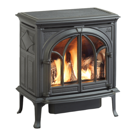
Jøtul GF 200 DV II MV
Lillehammer
Direct Vent Gas Stove
Pilot-on Demand Ignition
Installation and
Operation Instructions
Conforms to ANSI Z21.88-2016 • CSA 2.33-2016,
and CAN/CGA 2.17-M17.
INSTALLER: Leave this manual with the appliance.
CONSUMER: Keep this manual for future reference.
139955-01_ GF 200 DVII MV / Sept. 2019
WARNING: If the information in these
instructions is not followed exactly, a fire or
explosion may result causing property damage,
personal injury or loss of life.
– Do not store or use gasoline or other
flammable vapors and liquids in the
vicinity of this or any other appliance.
– WHAT TO DO IF YOU SMELL GAS
• Do not try to light any appliance.
• Do not touch any electrical switch; do
not use any phone in your building.
• Immediately call your gas supplier
from a neighbor's phone. Follow the gas
supplier's instructions.
• If you cannot reach your gas supplier, call
the fire department.
– Installation and service must be performed
by a qualified installer, service agency or
the gas supplier.
– In the Commonwealth of Massachusetts,
a carbon monoxide (CO) detector shall
be installed in the same room as the
appliance.
This appliance may be installed in an aftermarket,
permanently located, manufactured home or
mobile home, where not prohibited by local codes.
This appliance is only for use with the types of gas
indicated on the rating plate. A conversion kit is
supplied with the appliance.
DANGER
!
A barrier designed to reduce the burn hazard
from the glass viewing area is provided with this
appliance and shall be installed for the protection
of children and other at-risk individuals.
HOT GLASS WILL
CAUSE BURNS
.
DO NOT TOUCH GLASS
UNTIL COOLED.
NEVER ALLOW CHILDREN
TO TOUCH GLASS.
1
Advertisement
Table of Contents

Related Manuals for Jøtul Lillehammer


Summary of Contents for Jøtul Lillehammer
- Page 1 – In the Commonwealth of Massachusetts, Jøtul GF 200 DV II MV a carbon monoxide (CO) detector shall be installed in the same room as the Lillehammer Direct Vent Gas Stove appliance. Pilot-on Demand Ignition This appliance may be installed in an aftermarket, permanently located, manufactured home or mobile home, where not prohibited by local codes.
- Page 2 139955-01 GF 200 DVII MV / Sept. 2019 THIS OWNER’S MANUAL PROVIDES INFORMATION TO ENSURE SAFE INSTALLATION AND EFFICIENT, DEPENDABLE OPERATION OF YOUR FIREPLACE INSERT. PLEASE READ THESE INSTRUCTIONS IN THEIR ENTIRETY AND MAKE THEM AVAILABLE TO ANYONE USING OR SERVICING THIS GAS APPLIANCE.
-
Page 3: Table Of Contents
139955-01_ GF 200 DVII MV / Sept. 2019 Table of Contents Jøtul GF DV II MV Lillehammer Direct Vent Gas Heater Service Tools ..........4 Manufactured and Distributed by: Specifications ..........5 Jøtul North America General Information ........6 Gorham, Maine U.S.A. - Page 4 139955-01 GF 200 DVII MV / Sept. 2019 We recommend that Installation Requirements for the � our gas products be Commonwealth of Massachusetts installed and serviced by THIS PRODUCT MUST BE INSTALLED BY A professionals who are LICENSED MASTER OR JOURNEYMAN PLUMBER certified in the U.S.
-
Page 5: Specifications
Height Dimensions with Optional Legs: Long Legs - add 2 1/4 in. (57 mm) The Jøtul GF 200 DV II MV Lillehammer gas stove is Jøtul GF 200 DV II MV Accessories designed to burn NATURAL GAS or PROPANE only. -
Page 6: General Information
139955-01 GF 200 DVII MV / Sept. 2019 General Information Safety Information IMPORTANT: SAVE THESE INSTRUCTIONS. Due to the high operating temperatures this appliance should be located out of traffic and away from 1. The installation and repair of this appliance must be furniture and draperies. -
Page 7: Location
139955-01_ GF 200 DVII MV / Sept. 2019 Stove Setup Location Inspect the stove for damage and contact your dealer In selecting a location for the stove, consider the following immediately if any is found. Check contents of the points: Miscellaneous Kit against the lists on p. - Page 8 Corner: 2” (50 mm) Figure 3. Jøtul GF 200 DV MV Sides: 3” (76 mm) Mantel Clearances: Lillehammer stove flush with 52 1/2 in. (1333 mm) fireplace face. Minimum Clearances between Vent Pipe and 51 in. (1295 mm) Combustible Materials: Add 2 1/4 inches 49 1/2 in.
- Page 9 139955-01_ GF 200 DVII MV / Sept. 2019 Venting Requirements Both stoves may be installed with a vertical or horizon- Intake Air Restriction tal termination and must conform to the configuration requirements described in this section. This appliance is You may need to restrict air intake to the burner, depend- approved for use with vent systems from the following ing on the stove vent configuration.
-
Page 10: Clearances
139955-01 GF 200 DVII MV / Sept. 2019 Vertical Vent Termination 15 Ft. The Jøtul GF 200 DV II MV is approved for vertical venting (457.2 cm) through a ceiling or to a roof termination following these guidelines: The termination should fall within the shaded area of ... - Page 11 139955-01_ GF 200 DVII MV / Sept. 2019 High Wind Exhaust Gas Venting Through a Fireplace Intake Air Max. Co-linear Co-linear Vent Installation Height 15 ft. This appliance may be vented through a masonry or Class (10.66 m) A prefabricated chimney using a Co-linear Flexible Vent Min.
-
Page 12: Horizontal Termination
139955-01 GF 200 DVII MV / Sept. 2019 Horizontal Vent Termination Wall Cut-out Opening: Cut-out dimensions will vary pipe. Follow the specific vent manufacturer’s instructions. Code standards require 2” clearance to combustible materials above the vent pipe and 1” clearance around the sides and bottom. - Page 13 139955-01_ GF 200 DVII MV / Sept. 2019 Max. 4 ft. Horizontal Wall Thimble and Trim Collar Wall Shield Installation The decorative Wall Shield, included in the Miscellaneous Hardware bag, is used to obscure the vent hole in the wall in installations vented directly off the rear of the stove.
- Page 14 139955-01 GF 200 DVII MV / Sept. 2019 Horizontal Termination Clearance Vent Terminal Air Supply Terminals Prohibited in this Area Figure 17. Vent Terminal Clearances - National Fuel Gas Code. Canadian Installations U.S. Installations Clearance above grade, veranda, porch, deck, 12 in.
-
Page 15: Mobile Home Installation
139955-01_ GF 200 DVII MV / Sept. 2019 Mobile Home Installation Fuel Conversion These appliances can be installed for use in a mobile This appliance is shipped from the factory equipped to home in the U.S. and Canada provided: burn NATURAL GAS only. If PROPANE gas is to be used as fuel, the appliance must first be converted for use with 1. - Page 16 139955-01 GF 200 DVII MV / Sept. 2019 Fuel Conversion Procedure 1. Turn off gas supply to stove. 16. Apply gas to the system and check for leaks using a leak test solution or electronic gas detector. 2. Remove the stove Top Plate (3). NEVER USE AN OPEN FLAME TO CHECK FOR GAS LEAKS.
-
Page 17: Gas Connection
139955-01_ GF 200 DVII MV / Sept. 2019 Gas Supply Connection NOTE: If the optional Blower will be installed, use a 90° Pilot Head Elbow off the valve to create adequate clearance for the Orifice main gas line. The gas supply line connection is made to the valve just Retainer inside the left rear leg. -
Page 18: Gas Pressure
Pressure Test: Attach a manometer to the appropriate The GF 200 DV MV Lillehammer may be adjusted for alti- test point on the valve. See fig. 24. The gauge connections tude over 2000 ft. (610 - 1371 m). Check with your gas sup- are located on the front of the valve under the On/Off/Pi- lot- knob. -
Page 19: Air Shutter Adjustment
139955-01_ GF 200 DVII MV / Sept. 2019 Flame Appearance - Air Shutter Adjustment WARNING: AIR SHUTTER ADJUSTMENTS SHOULD ONLY High Altitude Orifice Chart BE PERFORMED BY A QUALIFIED PROFESSIONAL SERVICE Jøtul GF 200 DV II MV TECHNICIAN. The air shutter setting at the burner orifice can be adjust- Orifice Elevation Fuel... -
Page 20: Remote Control
139955-01 GF 200 DVII MV / Sept. 2019 Optional Wall Thermostat or Log Set Installation Remote Control NOTE: Install the optional Brick Kit, if appropriate, before Use only a 750 millivolt DC two-wire circuit thermostat installing the Log Set. See page 30. with this appliance. -
Page 21: System Check
139955-01_ GF 200 DVII MV / Sept. 2019 System Check Pilot Head 1” 1. PURGING THE GAS LINE: When lighting the appliance Ignitor (25mm) 3/8” for the first time, it will take a few moments to clear 1/8” (8mm) the gas line of air. Once this purge is complete, the (3mm) Min. -
Page 22: Operation
139955-01 GF 200 DVII MV / Sept. 2019 Operation Familiarize yourself with the controls of your stove. Make sure that anyone else using the appliance is also familiar with the controls and operation procedures. Always follow the Lighting Instructions located on the inside back cover of this manual and also on the Rating Plate attached to the stove. - Page 23 139955-01_ GF 200 DVII MV / Sept. 2019 NOTE: INSPECT THE GLASS SURFACE FOR SCRATCHES AS THESE CAN WEAKEN THE PANEL TENSILE STRENGTH. REPLACE THE PANEL IF ANY SCRATCHES ARE FOUND. USE ONLY JOTUL PN 220576. DO NOT USE ANY OTHER TYPE Glass and Gasket Replacement OF GLASS.
- Page 24 139955-01 GF 200 DVII MV / Sept. 2019 Optional Blower # 155631 Contents Tools Required 1. Blower • 1/4” socket driver CONNECT THE GAS SUPPLY TO THE 2. Snapstat Wire Harness • 10 mm socket STOVE BEFORE INSTALLING THIS 3. Control Box driver or wrench BLOWER.
- Page 25 139955-01_ GF 200 DVII MV / Sept. 2019 Figure 37 . Attach Blower to the stove bottom and connect wires to Snapstat. Mounting Bracket for GF100 DV II MV Snapstat Connectors #8 x 1/2” sheet M6 x 12 mm metal screws Hex Bolts 4.
- Page 26 139955-01 GF 200 DVII MV / Sept. 2019 GF 200 DV II and DV II MV Illustrated Parts Breakdown / Firebox Assembly Figure 39.
-
Page 27: Glass Replacement
139955-01_ GF 200 DVII MV / Sept. 2019 GF 200 DV II & DV II MV Firebox Assembly Parts List Part Description Part Number Part Description Part Number Rear Shroud, Matte Black ....22055592 Rear Log, (two-piece) ......221104 Rear Shroud, Jøtul Iron ....22055585 Log Set w/ Embers ......... -
Page 28: Illustrated Parts Breakdown
139955-01 GF 200 DVII MV / Sept. 2019 Illustrated Parts Breakdown / Cast Iron and Associated Hardware Figure 40. Jøtul GF 200 DV MV Accessories Cast Iron Parts Matte Black Blue Black Majolica Paint Enamel Brown Enamel • Fuel Conversion Kit - LP ..........155626 Top Casting 10390692 10390627... - Page 29 139955-01_ GF 200 DVII MV / Sept. 2019 CAUTION! Tools Required: Safety glasses and gloves THE BRICK PANELS ARE EXTREMELY FRAGILE. HANDLE WITH CARE. WEAR SAFETY GLOVES TO PROTECT HANDS. Upper Panel 221117 Left Panel Right Panel 221114 221115 1. Remove the Top Plate. Simply lift it up off of the stove body.
- Page 30 139955-01 GF 200 DVII MV / Sept. 2019 Jøtul Gas Product suffer damage from thermal stress). 2) Damage due to incorrect installations not in conformance with the installa- Warranty tion instructions contained in this owner’s manual or local and/or national fire and building regulations.
-
Page 31: Lighting Instructions
LIGHTING INSTRUCTIONS 139955-01_ GF 200 DVII MV / Sept. 2019 FOR YOUR SAFETY, READ BEFORE LIGHTING. WARNING: IF YOU DO NOT FOLLOW THESE INSTRUCTIONS EXACTLY, A FIRE OR EXPLOSION MAY RESULT CAUS- ING PROPERTY DAMAGE, PERSONAL INJURY, OR LOSS OF LIFE. A. - Page 32 139955-01 GF 200 DVII MV / Sept. 2019 This appliance must be installed in conformance with local and national building regulations. Before beginning the installation, it is important that the these instructions be carefully read and understood. Jøtul maintains a policy of continual product development. Consequently, products may differ in specification, color or type of accessories from those illustrated or described in various publications.
Need help?
Do you have a question about the Lillehammer and is the answer not in the manual?
Questions and answers