Table of Contents
Advertisement
Quick Links
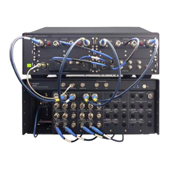
S9106AC-2IF, -4UP, and -42D
5G FR1 Multi-port
Transceiver Solutions
380 MHz to 6 GHz and 7 to 15 GHz
S9106AC-2IF
Describes the Keysight S9106AC-2IF, -4UP, and -42D 5G FR1 Multi-port Transceiver Solutions which are
streamlined, non-signaling measurement systems that enable automated testing of 5G New Radio (5G NR)
infrastructure equipment:
S9106AC-2IF 5G FR1 Multi-port Transceiver contains: two Transceiver Channels, 380 MHz to 6 GHz,
with MIMO Subsystem and 7 to 15 GHz High IF on Two Channels
S9106AC-4UP 5G FR1 Multi-port Transceiver contains: four Transceiver Channels, 380 MHz to 6 GHz,
with MIMO Subsystem
S9106AC-42D 5G FR1 Multi-port Transceiver contains: four Transceiver Channels, 380 MHz to 6 GHz,
with MIMO Subsystem and 7 to 15 GHz High IF on Two Channels
S9106AC-4UP
S9106AC-42D
STARTUP GUIDE
Advertisement
Chapters
Table of Contents

Related Manuals for Keysight Technologies S9106AC-42D


Summary of Contents for Keysight Technologies S9106AC-42D
- Page 1 S9106AC-4UP 5G FR1 Multi-port Transceiver contains: four Transceiver Channels, 380 MHz to 6 GHz, with MIMO Subsystem S9106AC-42D 5G FR1 Multi-port Transceiver contains: four Transceiver Channels, 380 MHz to 6 GHz, with MIMO Subsystem and 7 to 15 GHz High IF on Two Channels ...
- Page 2 WARRANT THIRD-PARTY SYSTEM- computer software pursuant to the FAR LEVEL (COMBINATION OF CHASSIS, and the DFARS and are set forth © Keysight Technologies, Inc. 2021, 2022 CONTROLLERS, MODULES, ETC.) specifically in writing elsewhere in the No part of this manual may be PERFORMANCE, SAFETY, OR EULA.
-
Page 3: Table Of Contents
3. 2. 1 Connectors, 10 MHz Ref In/Out on the Rugged Front Panel 3. 2. 2 Connectors, S9106AC-2IF on the Rugged Front Panel 3. 2. 3 Connectors, S9106AC-4UP on the Rugged Front Panel 3. 2. 4 Connectors, S9106AC-42D on the Rugged Front Panel 3. 2. 5 Connectors, M9037A PXIe Embedded Controller 3. 2. 6 Connectors, S9106AC-2IF, -4UP, and -42D on the PXIe Chassis Rear Panel 3. - Page 4 6. 3 S9106AC-42D: Detailed Steps to Verify Operation 6. 3. 1 Connect AC Power Cords & Power On Equipment 6. 3. 2 Verify X-Apps Controls S9106AC-42D RF Ports at 3 GHz 6. 3. 3 Verify X-Apps Controls S9106AC-42D High IF Ports at 10 GHz 7 MIMO...
-
Page 5: S9106Ac-2If, -4Up, And -42D 5G Fr1 Multi-Port Transceiver Solutions
1 Overview Keysight S9106AC-2IF, -4UP, and -42D 5G FR1 Multi-port Transceiver Solutions are streamlined, non-signaling measurement systems that enable automated testing of 5G New Radio (5G NR) infrastructure equipment. S9106AC-2IF 5G FR1 S9106AC-4UP 5G FR1 S9106AC-42D 5G FR1 Multi-port Transceiver contains: Multi-port Transceiver contains: Multi-port Transceiver two Transceiver Channels, four Transceiver Channels, contains: four Transceiver... - Page 6 S9106AC-2IF, -4UP, and -42D 5G FR1 Multi-port Transceiver Solutions, Startup Guide...
-
Page 7: Review Safety Requirements
2 Review Safety Requirements 2 Review Safety Requirements Review all safety information in this section before operating any of the equipment: Warning Statements and Symbols on page 3 Safety on page 4 Weight and Dimensions on page 6 Handling and Lifting on page 6 Cleaning on page 7 Environmental Conditions (Operating) on page 8 Review Safety Requirements on page 3 Review Safety Requirements on page 3 Ventilation on page 9 Location and Mounting on page 10 Power Requirements on page 11... -
Page 8: Safety
2 Review Safety Requirements 2. 2 Safety The products described in this document have been designed and tested in accordance with accepted industry standards and have been supplied in a safe condition. This documentation contains information and warnings that must be followed by the user to ensure safe operation and to maintain products in a safe condition. - Page 9 2 Review Safety Requirements 2. 2. 3 General Safety Notices If these products are not used as specified, the protection provided by the equipment could be impaired. These products must be used in a normal condition (in which all means for protection are intact) only. This is a Safety Protection Class I Product (provided with a protective earthing ground incorporated in the power cord).
-
Page 10: Weight And Dimensions
2 Review Safety Requirements 2. 3 Weight and Dimensions S9106AC Base System (a PXIe chassis with modules, rugged panel, and cables): Height: 192.4 mm (7.6 in); with feet removed Height: 197.8 mm (7.8 in); with feet installed Width: 449.5 mm (17.7 in); with rugged panel Depth: 568.9 mm (22.4 in);... -
Page 11: Cleaning
2 Review Safety Requirements 2. 5 Cleaning Clean the outside of Keysight products with a soft, lint-free, slightly dampened cloth. Do not use detergent or chemical solvents. To prevent electrical shock, disconnect from Mains before cleaning. Use a dry cloth or one slightly dampened with water to clean the external case parts. -
Page 12: Environmental Conditions (Operating)
2 Review Safety Requirements 2. 6 Environmental Conditions (Operating) The Keysight S9106AC-2IF, -4UP, and -42D 5G FR1 Multi-port Transceiver Solutions are designed for use in Installation Category II and Pollution Degree 2, per IEC 61010 Second Edition and 664 respectively. The Keysight S9106AC-2IF, -4UP, and -42D 5G FR1 Multi-port Transceiver Solutions are designed for use in the following conditions: For indoor use only Altitude up to 6,561.68 ft (2,000 m) -
Page 13: Ventilation
2 Review Safety Requirements 2. 7 Ventilation VENTILATION REQUIREMENTS: When installing the product into a cabinet, the convection into and out of the product must not be restricted. Consideration shall also be given to the individual instruments to avoid having the heated discharge of one instrument, now becoming the cooling intake air for another instrument. -
Page 14: Location And Mounting
2 Review Safety Requirements 2. 8 Location and Mounting Consider ergonomics when locating any keyboard or mouse which will be used in connection with an instrument. Install the Keysight S9106AC-2IF, -4UP, and -42D 5G FR1 Multi-port Transceiver Solutions so that the detachable power cords are readily identifiable and is easily reached by the operator. -
Page 15: Power Requirements
2 Review Safety Requirements 2. 9 Power Requirements 100/120 VAC, 220/240 VAC 50/60 Hz 1200 W Max (Lower range), 1300 W Max (Upper range) "WARNING: Safety of any system incorporating the equipment is the responsibility of the assembler of the system." The Keysight S9106AC-2IF, -4UP, and -42D 5G FR1 Multi-port Transceiver Solutions do not contain customer serviceable fuses. - Page 16 2 Review Safety Requirements 2. 9. 1 Before Applying Power Verify that all safety precautions are taken. Make all connections to the unit before applying power. Note the external markings described under Front and Rear Panel Symbols on page 17. The Mains wiring and connectors shall be compatible with the connector used in the premise electrical system.
- Page 17 2 Review Safety Requirements 2. 9. 6 Outlet Must Be In Good Working Order The AC Voltage source (outlet) must be in proper working order and provide a secure electrical connection. DO NOT use outlet if the power cord does not match the outlet. DO NOT use outlet if it is damaged or if the voltage is outside the required range.
-
Page 18: Battery Replacement On The M9037A Controller
2 Review Safety Requirements 2. 10 Battery Replacement on the M9037A Controller CMOS Backup Battery Keysight’s M9037A is equipped with a 3.0 V "coin cell" lithium battery. This battery powers the clock circuit and retains configuration Danger of explosion if memory in CMOS RAM while the system is battery is incorrectly turned off. -
Page 19: Ac Power Cord
2 Review Safety Requirements 2. 11 AC Power Cord The Keysight S9106AC-2IF, -4UP, and -42D 5G FR1 Multi-port Transceiver Solutions are equipped with three-wire power cords, in accordance with international safety standards. These power cords ground the Keysight S9106AC-2IF, -4UP, and -42D 5G FR1 Multi-port Transceiver Solutions cabinet when connected to an appropriate power line outlet. -
Page 20: Protecting Against Electrostatic Discharge (Esd)
2 Review Safety Requirements 2. 12 Protecting Against Electrostatic Discharge (ESD) Electrostatic discharge (ESD) can damage or destroy electronic components (the possibility of unseen damage caused by ESD is present whenever components are transported, stored, or used). Shipping Materials and ESD Keysight’s chassis and instrument modules are shipped in materials which prevent static electricity damage. -
Page 21: Front And Rear Panel Symbols
2 Review Safety Requirements 2. 13 Front and Rear Panel Symbols Symbols that may be on the exterior of S9106AC-2IF, S9106AC-4UP, and S9106AC- 42D hardware components are: Symbol Description This symbol is used to indicate power ON and to mark the position of the instrument power line switch. - Page 22 2 Review Safety Requirements Symbol Description The crossed out wheeled bin symbol indicates that separate collection for waste electric and electronic equipment (WEEE) is required, as obligated by the EU DIRECTIVE and other National legislation. Please refer to www.keysight.com/go/takeback to understand your Trade in options with Keysight in addition to product takeback instructions.
-
Page 23: Returning For Service
2 Review Safety Requirements 2. 14 Returning for Service Should it become necessary to return the system for repair or service, follow these steps: 1. Review the warranty information shipped with the product. 2. Contact Keysight to obtain a Return Material Authorization (RMA) and a return address. - Page 24 S9106AC-2IF, -4UP, and -42D 5G FR1 Multi-port Transceiver Solutions, Startup Guide...
-
Page 25: Review Hardware
Hardware Components on page 22 Connector Descriptions on page 24 Connectors, 10 MHz Ref In/Out on the Rugged Front Panel on page 24 Connectors, S9106AC-2IF on the Rugged Front Panel on page 25 Connectors, S9106AC-4UP on the Rugged Front Panel on page 26 Connectors, S9106AC-42D on the Rugged Front Panel on page 27 Connectors, S9106AC-2IF, -4UP, and -42D on the PXIe Chassis Rear Panel on page 30 Connectors, E7770A Common Interface Unit (CIU) for the S9106AC-2IF and S9106AC-42D 5G FR1 Multi-port Transceiver on page 32 S9106AC-2IF, -4UP, and -42D 5G FR1 Multi-port Transceiver Solutions, Startup Guide... -
Page 26: Hardware Components
3 Review Hardware 3. 1 Hardware Components The S9106AC is available in three standard configurations. Keysight S9106AC-2IF 5G FR1 Multi-port Transceiver on page 41 includes: one S9106AC Base System (PXIe chassis and two M9410A PXIe VXT Vector Transceivers) one E7770A Common Interface Unit (CIU) with two E7770A-HB2 CIU Channel Cards, 7 to 15 GHz High IF one E7770A-LA2 CIU LO Card one E7770A-LD2 CIU LO Distribution Card The S9106AC-2IF, two-channel configuration, consists of two transceivers providing two RF Tx channels or two RF Rx channels, or two High IF Tx channels or two High IF Rx channels operating in one frequency range at a time:... - Page 27 two E7770A-HB2 CIU Channel Cards, 7 to 15 GHz High IF one E7770A-LA2 CIU LO Card one E7770A-LD2 CIU LO Distribution Card The S9106AC-42D, four-channel configuration, consists of four transceivers providing four RF Tx channels or four RF Rx channels, or two High IF Tx channels or two High IF Rx channels operating in one frequency range at a time: FR1 RF frequencies ranging from 380 MHz to 6 GHz...
-
Page 28: Connector Descriptions
3 Review Hardware 3. 2 Connector Descriptions 3. 2. 1 Connectors, 10 MHz Ref In/Out on the Rugged Front Panel 10 MHz Ref Out (Connects from M9300A PXIe Reference 10 MHz Out.) Connector BNC (f) Amplitude 9.5 dBm, nominal 10 MHz Ref In (Connects behind rugged panel, to M9300A PXIe Reference Ref In, and locks to another reference with a value of 10 MHz or 100 MHz.) Connector BNC (f) -
Page 29: Connectors, S9106Ac-2If On The Rugged Front Panel
3 Review Hardware 3. 2. 2 Connectors, S9106AC-2IF on the Rugged Front Panel CIU DUT Interconnect IF Out Connector Type-N (f), 50 Ω, nominal Frequency Range 380 MHz to 6 GHz IF In Connector Type-N (f), 50 Ω, nominal Frequency Range 380 MHz to 6 GHz RF Transceiver .380 - 6 GHz RF Out Connector... -
Page 30: Connectors, S9106Ac-4Up On The Rugged Front Panel
3 Review Hardware 3. 2. 3 Connectors, S9106AC-4UP on the Rugged Front Panel RF Transceiver .380 - 6 GHz RF Out Connector Type-N (f), 50 Ω, nominal Frequency Range 380 MHz to 6 GHz Amplitude 30 VDC, +27 dBm Maximum Reverse Input Power RF In Connector Type-N (f), 50 Ω, nominal Frequency Range... -
Page 31: Connectors, S9106Ac-42D On The Rugged Front Panel
3 Review Hardware 3. 2. 4 Connectors, S9106AC-42D on the Rugged Front Panel CIU DUT Interconnect IF Out Connector Type-N (f), 50 Ω, nominal Frequency Range 380 MHz to 6 GHz IF In Connector Type-N (f), 50 Ω, nominal Frequency Range 380 MHz to 6 GHz RF Transceiver .380 - 6 GHz... -
Page 32: Connectors, M9037A Pxie Embedded Controller
3 Review Hardware 3. 2. 5 Connectors, M9037A PXIe Embedded Controller Status LEDs PWR (Green) On, indicates power supply to embedded controller is good. SSD (Amber) Flashes when Solid State Drive is active. Link (Green) Indicates PCIe Link status: Off = No link; Blinking @ 1 Hz = Gen1 speed Blinking @ 2 Hz = Gen2 speed On steady = Gen3 speed... - Page 33 3 Review Hardware CMOS Backup Battery WARNING Keysight’s M9037A is equipped with a 3.0 V "coin Danger of explosion if cell" lithium battery. This battery powers the battery is incorrectly clock circuit and retains configuration memory in replaced. CMOS RAM while the system is turned off. Replace only with the same or equivalent type recommended.
-
Page 34: Connectors, S9106Ac-2If, -4Up, And -42D On The Pxie Chassis Rear Panel
3 Review Hardware 3. 2. 6 Connectors, S9106AC-2IF, -4UP, and -42D on the PXIe Chassis Rear Panel AC Line Input (Use the AC line cord supplied with the S9106AC.) Connector, Three-Prong 100/120 V, 50/60 Hz, 1200 W MAX (Lower range) 220/240 V, 50/60 Hz, 1300 W MAX (Upper range) See also Battery Replacement on the M9037A... - Page 35 3 Review Hardware INHIBIT/VOLTAGE MON (Use for remote inhibit and power rail monitoring.) Connector DB-9 For details on use, see the Keysight PXIe Chassis User Guide (M9019-90003). 10 MHz REF IN and OUT Connectors, Rear Panel BNC (f), 50 Ω, nominal Frequency Input 10 MHz ±100 PPM Input Signal...
-
Page 36: Connectors, E7770A Common Interface Unit (Ciu) For The S9106Ac-2If And S9106Ac-42D 5G Fr1 Multi-Port Transceiver
3 Review Hardware 3. 2. 7 Connectors, E7770A Common Interface Unit (CIU) for the S9106AC-2IF and S9106AC-42D 5G FR1 Multi-port Transceiver The E7770A Common Interface Unit (CIU) is only included in the S9106AC-2IF 5G FR1 Multi-port Transceiver and S9106AC-42D 5G FR1 Multi-port Transceiver configurations. If using a S9106AC-4UP 5G FR1 Multi-port Transceiver configuration, the E7770A Common Interface Unit (CIU) is not used; proceed to Install Hardware on page 39. 3. 2. 7. 1 Connectors, E7770A-LA2 CIU LO Card The E7770A-LA2 CIU LO Card provides the conversion frequency... -
Page 37: Connectors, E7770A-Ld2 Ciu Lo Distribution Card
3 Review Hardware 3. 2. 7. 2 Connectors, E7770A-LD2 CIU LO Distribution Card The E7770A-LD2 CIU LO Distribution Card distributes the LO signal, from the E7770A-LA2 CIU LO Card, to the E7770A-HB2 CIU Channel Card, 7 to 15 GHz High IF. LO In Connector SMA (f), 50 Ω, nominal LO Card LO Aux Out to LO Distribution Card LO In. Install Hardware on page 39. -
Page 38: Connectors, E7770A-Hb2 Ciu Channel Card, 7 To 15 Ghz High If
3 Review Hardware 3. 2. 7. 3 Connectors, E7770A-HB2 CIU Channel Card, 7 to 15 GHz High IF The E7770A-HB2 CIU Channel Card, 7 to 15 GHz High IF provides connectivity between the test system hardware and the IF interface on the device under test (DUT). IF In A Connector Type-N (f), 50 Ω, nominal DL IF input Channel A. -
Page 39: Connectors, E7770A Ciu Rear Panel
3 Review Hardware 3. 2. 7. 4 Connectors, E7770A CIU Rear Panel The E7770A CIU rear panel contains rear connections for the CONTROLLER CARD and all Channel Cards. The rear panel of the E7770A CIU is also labeled with all required safety and compliance indicators and contains the Mains switch where the AC power cable is connected. -
Page 40: Connectors, E7770A Ciu Rear Panel, Channel Cards
Channel Card (labeled: 1A, 1B, 2A, 2B, 3A, 3B, 4A, 4B) corresponds to a Channel Card available from the front of the E7770A CIU. In the S9106AC-2IF 5G FR1 Multi-port Transceiver and S9106AC-42D 5G FR1 Multi-port Transceiver configurations, only rear panel connectors for CHANNEL 1A and CHANNEL 1B are usable with the E7770A-HB2 CIU Channel Card, 7 to 15 GHz High IF. -
Page 41: Connectors, E7770A Ciu Rear Panel, Controller Card
3 Review Hardware 3. 2. 7. 6 Connectors, E7770A CIU Rear Panel, Controller Card Each E7770A CIU contains a single CONTROLLER CARD. The status of the E7770A CIU is identified using the status lights on the CONTROLLER CARD. Status LEDs Top Left LED, Green On, indicates +12 V supply if okay. - Page 42 S9106AC-2IF, -4UP, and -42D 5G FR1 Multi-port Transceiver Solutions, Startup Guide...
-
Page 43: Install Hardware
4 Install Hardware 4 Install Hardware Before installing hardware, Review Safety Requirements on page 3. 4. 1 Standard Configurations The S9106AC is available in three standard configurations: Keysight S9106AC-2IF 5G FR1 Multi-port Transceiver on page 41 includes: one S9106AC Base System (PXIe chassis and two M9410A PXIe VXT Vector Transceivers) one E7770A Common Interface Unit (CIU) with two E7770A-HB2 CIU Channel Cards, 7 to 15 GHz High IF one E7770A-LA2 CIU LO Card one E7770A-LD2 CIU LO Distribution Card... - Page 44 one E7770A-LA2 CIU LO Card one E7770A-LD2 CIU LO Distribution Card The S9106AC-42D, four-channel configuration, consists of four transceivers providing four Tx channels and four Rx channels. All four channels can operate in the RF frequency range. Two of the four channels can also be used in the High IF frequency range, with each channel operating in one frequency range at a time:...
-
Page 45: Keysight S9106Ac-2If 5G Fr1 Multi-Port Transceiver
4 Install Hardware 4. 2 Keysight S9106AC-2IF 5G FR1 Multi-port Transceiver S9106AC-2IF, -4UP, and -42D 5G FR1 Multi-port Transceiver Solutions, Startup Guide... - Page 46 4 Install Hardware Connect the hardware as described in the following table. Item Connection To... From... 8121-1351, LAN Cable, Patch-5E RJ-45 (m) to RJ-45 (m) 24-AWG 8-Conductor PVC, 2133.6 mm (84 in), Blue or equivalent Connect M9037A PXIe Embedded Controller, LAN 2 to E7770A CIU, CONTROL (rear panel).
-
Page 47: Connect Cables, Lan Cables, A Display, A Keyboard & Mouse
4 Install Hardware Item Connection To... From... to S9106AC-2IF labeled: "To DUT IF In" (front panel). loop-back cable with adapters (Not included with S9106AC-2IF.) Used during verification only; connect RF loop-back cable and adapters from ➀ ➁ RF Out to RF In on Transceiver 1 and then Transceiver 2. -
Page 48: Connect Ac Power Cords & Power On Equipment
4 Install Hardware 4. 2. 2 Connect AC Power Cords & Power On Equipment 1. Power on the E7770A CIU Rear Mains Switch, located on the rear panel. 2. Power on the E7770A CIU AC Power Switch, located on the left front panel. 3. -
Page 49: Keysight S9106Ac-4Up 5G Fr1 Multi-Port Transceiver
4 Install Hardware 4. 3 Keysight S9106AC-4UP 5G FR1 Multi-port Transceiver Connect the hardware as described in the following table. Item Connection To... From... loop-back cable with adapters (Not included with S9106AC-4UP.) During verification only, connect a loop-back cable from RF OUT to RF IN on Transceiver 1 and then on Transceiver 2, Transceiver 3, and Transceiver 4. -
Page 50: Connect Cables, Lan Cables, A Display, A Keyboard & Mouse
4 Install Hardware 4. 3. 1 Connect Cables, LAN Cables, a Display, a Keyboard & Mouse 1. Connect cables as shown in the equipment setup above. 2. Connect LAN 1 (top) to the Site LAN at your facility. 3. Connect a Display, Keyboard & Mouse (Not included with S9106AC-4UP). 4. -
Page 51: Keysight S9106Ac-42D 5G Fr1 Multi-Port Transceiver
4 Install Hardware 4. 4 Keysight S9106AC-42D 5G FR1 Multi-port Transceiver S9106AC-2IF, -4UP, and -42D 5G FR1 Multi-port Transceiver Solutions, Startup Guide... - Page 52 SMA (m) to Type-N (m), 1100 mm (43.3 in) Transceiver 1, CIU RF Interconnections Connect E7770A-HB2 CIU CHANNEL 1A, DUT IF OUT (rear) to S9106AC-42D labeled: "From DUT IF Out" (front panel). Connect E7770A-HB2 CIU CHANNEL 1B, DUT IF IN (rear) to S9106AC-42D labeled: "To DUT IF In" (front panel).
-
Page 53: Connect Cables, Lan Cables, A Display, A Keyboard & Mouse
2. Connect LAN 1 (top) to the Site LAN at your facility. ➅ 3. Connect LAN 2 (bottom) to the E7770A CIU CONTROL (rear panel). 4. Connect a Display, Keyboard & Mouse (Not included with S9106AC-42D). S9106AC-2IF, -4UP, and -42D 5G FR1 Multi-port Transceiver Solutions, Startup Guide... -
Page 54: Connect Ac Power Cords & Power On Equipment
1. Power on the E7770A CIU Rear Mains Switch, located on the rear panel. 2. Power on the E7770A CIU AC Power Switch, located on the left front panel. 3. Power on the S9106AC-42D AC Power Switch, located on the right front panel. S9106AC-2IF, -4UP, and -42D 5G FR1 Multi-port Transceiver Solutions, Startup Guide... -
Page 55: Install Software
5 Install Software 5 Install Software Each S9106AC-2IF, S9106AC-4UP, and S9106AC-42D standard configuration includes an M9037A PXIe Embedded Controller; all required software comes pre-installed. Proceed to Verify Operation on page 53. S9106AC-2IF, -4UP, and -42D 5G FR1 Multi-port Transceiver Solutions, Startup Guide... - Page 56 S9106AC-2IF, -4UP, and -42D 5G FR1 Multi-port Transceiver Solutions, Startup Guide...
-
Page 57: Verify Operation
To verify operation of the S9106AC-42D 5G FR1 Multi-port Transceiver Connect AC Power Cords & Power On Equipment on page 67 Verify X-Apps Controls S9106AC-42D RF Ports at 3 GHz on page 68 Verify X-Apps Controls S9106AC-42D High IF Ports at 10 GHz on page 72 S9106AC-2IF, -4UP, and -42D 5G FR1 Multi-port Transceiver Solutions, Startup Guide... -
Page 58: S9106Ac-2If: Detailed Steps To Verify Operation
6 Verify Operation 6. 1 S9106AC-2IF: Detailed Steps to Verify Operation Connect AC Power Cords & Power On Equipment on page 54 Verify X-Apps Controls S9106AC-2IF RF Ports at 3 GHz on page 55 Verify X-Apps Controls S9106AC-2IF High IF Ports at 10 GHz on page 59 6. 1. 1 Connect AC Power Cords & Power On Equipment 1. -
Page 59: Verify X-Apps Controls S9106Ac-2If Rf Ports At 3 Ghz
6 Verify Operation After connecting AC power cords and powering on equipment, the following process must be repeated for each M9410A PXIe VXT Vector Transceiver and its selected X-Apps software pair in the system; the S9106AC-2IF 5G FR1 Multi-port Transceiver contains two M9410A PXIe VXTs that are labelled on the Rugged Front Panel as Transceiver 1 and Transceiver 2. - Page 60 6 Verify Operation 2. If it is not already running, start the Modular TRX software and review the interface; this interface is referred to as a Mode: The Modular TRX interface can be started as follows: Select the Start menu (lower-left corner icon) >...
- Page 61 6 Verify Operation 5. Set the RF Input to 3 GHz; this is RF Transceiver .380 - 6 GHz, RF In ➁ located on the Rugged Front Panel. a. Select Input/Output from the drop-down menu panel (top-right corner), select Input tab, select RF Input drop-down menu, and select RF Input. b.
- Page 62 6 Verify Operation 7. Verify IQ Analyzer Mode displays a signal at 3 GHz and –10 dBm. a. Select Peak Search from the drop-down menu panel (top-right corner). If there is a signal at 3 GHz of approximately –10 dBm, RF Out ➀...
-
Page 63: Verify X-Apps Controls S9106Ac-2If High If Ports At 10 Ghz
6 Verify Operation 6. 1. 3 Verify X-Apps Controls S9106AC-2IF High IF Ports at 10 GHz This process verifies operation of the RF Transceiver 7 - 15 GHz, RF Out ➃ RF In ➄ located on the Rugged Front Panel; these connectors may be referred to as: "High IF" or "DUT IF". RF Out ➃... - Page 64 6 Verify Operation RF In ➄ 2. Set the RF Input to 10 GHz; this is RF Transceiver 7 - 15 GHz, located on the Rugged Front Panel. a. Select Input/Output from the drop-down menu panel (top-right corner), select Input tab, select RF Input Port drop-down menu, and select DUT IF IN 1. b.
- Page 65 6 Verify Operation 4. Verify IQ Analyzer Mode displays a signal at 10 GHz and –10 dBm. a. Select Peak Search from the drop-down menu panel (top-right corner). If there is a signal at 10 GHz of approximately –10 dBm, RF Out ➃...
-
Page 66: S9106Ac-4Up: Detailed Steps To Verify Operation
6 Verify Operation 6. 2 S9106AC-4UP: Detailed Steps to Verify Operation Connect AC Power Cords & Power On Equipment on page 62 Verify X-Apps Controls S9106AC-4UP RF Ports at 3 GHz on page 63 6. 2. 1 Connect AC Power Cords & Power On Equipment 3. Connect an AC Power Cord to the S9106AC Base System right-rear panel. 4. -
Page 67: Verify X-Apps Controls S9106Ac-4Up Rf Ports At 3 Ghz
6 Verify Operation 6. 2. 2 Verify X-Apps Controls S9106AC-4UP RF Ports at 3 GHz This process verifies operation of the RF Transceiver .380 - 6 GHz, FR1 connectors: RF Out ➀ RF In ➁ RF Out ➀ RF In ➁ 1. - Page 68 6 Verify Operation The Modular TRX interface can be started as follows: Select the Start menu (lower-left corner icon) > Scroll down to "K" applications > Select the Keysight Modular Transceiver drop-down arrow > Scroll down the list and select LaunchModularTRX Each Mode looks different and has its own collection of measurement capabilities, controls, windows, and SCPI commands.
- Page 69 6 Verify Operation 5. Set the RF Input to 3 GHz; this is RF Transceiver .380 - 6 GHz, RF In ➁ located on the Rugged Front Panel. a. Select Input/Output from the drop-down menu panel (top-right corner), select Input tab, select RF Input drop-down menu, and select RF Input. b.
- Page 70 6 Verify Operation 7. Verify IQ Analyzer Mode displays a signal at 3 GHz and –10 dBm. a. Select Peak Search from the drop-down menu panel (top-right corner). If there is a signal at 3 GHz of approximately –10 dBm, RF Out ➀...
-
Page 71: S9106Ac-42D: Detailed Steps To Verify Operation
Connect AC Power Cords & Power On Equipment on page 67 Verify X-Apps Controls S9106AC-42D RF Ports at 3 GHz on page 68 Verify X-Apps Controls S9106AC-42D High IF Ports at 10 GHz on page 72 6. 3. 1 Connect AC Power Cords & Power On Equipment 1. Connect an AC Power Cord to the E7770A CIU right-rear panel. -
Page 72: Verify X-Apps Controls S9106Ac-42D Rf Ports At 3 Ghz
M9410A PXIe VXTs that are labelled on the Rugged Front Panel as Transceiver 1, Transceiver 2, Transceiver 3, and Transceiver 4. 6. 3. 2 Verify X-Apps Controls S9106AC-42D RF Ports at 3 GHz This process verifies operation of RF Transceiver .380 - 6 GHz, RF Out ➀... - Page 73 Each Mode runs within a screen (there can be multiple screens). Screens are shown as tabs across the top of the interface. IQ Analyzer Mode is included with the S9106AC-42D and appears as a tab with the label IQ Analyzer 1.
- Page 74 6 Verify Operation RF In ➁ 5. Set the RF Input to 3 GHz; this is RF Transceiver .380 - 6 GHz, located on the Rugged Front Panel. a. Select Input/Output from the drop-down menu panel (top-right corner), select Input tab, select RF Input drop-down menu, and select RF Input. b.
- Page 75 RF In ➁ RF Transceiver .380 - 6 GHz, of the S9106AC-42D are working properly. (The power level is only approximate because there is loss in the cable being used and this loss is not being corrected during the measurement.)
-
Page 76: Verify X-Apps Controls S9106Ac-42D High If Ports At 10 Ghz
6 Verify Operation 6. 3. 3 Verify X-Apps Controls S9106AC-42D High IF Ports at 10 GHz This process verifies operation of the RF Transceiver 7 - 15 GHz, RF Out ➃ RF In ➄ located on the Rugged Front Panel; these connectors may be referred to as: "High IF" or "DUT IF". - Page 77 6 Verify Operation 2. Set the RF Input to 10 GHz; this is RF Transceiver 7 - 15 GHz, RF In ➄ located on the Rugged Front Panel. a. Select Input/Output from the drop-down menu panel (top-right corner), select Input tab, select RF Input Port drop-down menu, and select DUT IF IN 1. b.
- Page 78 RF In ➄ RF Transceiver 7 - 15 GHz, of the S9106AC-42D are working properly. (The power level is only approximate because there is loss in the cable being used and this loss is not being corrected during the measurement.)
-
Page 79: Mimo
All of the previous sections must be completed before performing MIMO measurements with the S9106AC-2IF, S9106AC-4UP, or the S9106AC-42D. To set up and run MIMO on the S9106AC-2IF, S9106AC-4UP, or the S9106AC-42D. Refer to the Keysight MIMO Measurement Guide, M9410-90016 for the Keysight M9410A/M9411A VXT PXIe Vector Transceiver For DUT IF MIMO measurements, select the DUT IF ports. - Page 80 Contacting Keysight Assistance with test and measurements and information on finding a local Keysight office are available at: www.keysight.com/find/assist This information is subject to change without notice. © Keysight Technologies 2021, 2022 Edition 1, October, 2022 Printed in USA S9106-90001 www.keysight.com...
Need help?
Do you have a question about the S9106AC-42D and is the answer not in the manual?
Questions and answers