
Related Manuals for Keysight Technologies S9130A


Summary of Contents for Keysight Technologies S9130A
- Page 1 Keysight mmWave Reference Solutions S9130A Performance 5G Multi-band Vector Transceiver Getting Started Guide...
- Page 2 THESE TERMS, THE WARRANTY beyond those set forth in the TERMS IN THE SEPARATE EULA shall apply, except to the © Keysight Technologies, Inc. 2020 AGREEMENT WILL CONTROL. extent that those terms, rights, or No part of this manual may be...
- Page 3 Documentation is updated periodically. For the latest information about these products, including instrument software upgrades, application information, and product information, browse to one of the following URLs. More information about the test set can be found at: www.keysight.com/find/S9130A To receive the latest updates by email, subscribe to Keysight Email Updates at: http://www.keysight.com/find/MyKeysight Information on preventing instrument damage can be found at: www.keysight.com/find/PreventingInstrumentRepair...
-
Page 5: Table Of Contents
Contents Table of Contents Safety & Environmental Information 9 Elements of the System 10 Warning Statements and Symbols 11 Safety 12 Safety Compliance 12 Safe Installation 12 Acoustic statement (European Machinery Directive) 12 General Safety Notices 12 Environmental Conditions (Operating) 13 Environmental Information 13 EMC (Electromagnetic Compatibility) 14 South Korean Class A EMC declaration 14... - Page 6 Contents Application Licenses 32 Exterior Features 35 PXIe Subsystem Front Panel 36 PXIe Subsystem front panel: PXIe Chassis section 37 PXIe Subsystem front panel: Controller section 38 PXIe Subsystem front panel: RF Transceiver section 40 PXIe Subsystem front panel: mmWave Transceiver section 42 M1741A Exterior Panels 44 M1741A, DUT-facing side 44 M1741A, instrument-facing side 46...
- Page 7 PXIe System Controller 112 Controller documentation 112 Troubleshooting 113 Basic Operational Check 114 Identifying Problems 120 Where to get technical help 121 Returning the S9130A for Service 122 Calling Keysight Technologies 122 Locations for Keysight Technologies 123 Getting Started Guide...
- Page 8 Contents Getting Started Guide...
-
Page 9: Safety & Environmental Information
Keysight Wireless Solutions S9130A Performance 5G Multi-band Vector Transceiver Getting Started Guide Safety & Environmental Information The following topics can be found in this section: “Elements of the System” on page 10 “Warning Statements and Symbols” on page 11 “Safety” on page 12 “Environmental Conditions (Operating)”... -
Page 10: Elements Of The System
Safety & Environmental Information Elements of the System Elements of the System The three main elements of the S9130A will be referred to in this guide as follows: — PXIe Subsystem (all hardware in the enclosed PXIe chassis of instruments) —... -
Page 11: Warning Statements And Symbols
Safety & Environmental Information Warning Statements and Symbols Warning Statements and Symbols Caution and Warning notices are used in this document are described below. A CAUTION notice denotes a hazard. It calls attention to an operating procedure, practice, or the like that, if not correctly performed or adhered to, could result in damage to the product or loss of important data. -
Page 12: Safety
Safety & Environmental Information Safety Safety This product has been designed and tested in accordance with accepted industry standards, and has been supplied in a safe condition.The documentation contains information and warnings that must be followed by the user to ensure safe operation and to maintain the product in a safe condition. -
Page 13: Environmental Conditions (Operating)
Safety & Environmental Information Environmental Conditions (Operating) Environmental Conditions (Operating) This product is designed for use in the following conditions: — For indoor use only — Altitude up to 3048 m — Temperature 20 to 30°C — Maximum relative humidity 95% (non-condensing) This product is designed for use in INSTALLATION CATEGORY II and POLLUTION DEGREE 2. -
Page 14: Emc (Electromagnetic Compatibility)
Safety & Environmental Information EMC (Electromagnetic Compatibility) EMC (Electromagnetic Compatibility) This product complies with the essential requirements of the European Directive as well as current editions of the following standards (dates and editions are cited in the Declaration of Conformity): —... -
Page 15: Ventilation
Safety & Environmental Information Ventilation Ventilation VENTILATION REQUIREMENTS: When installing the instrument(s) into a cabinet, consideration shall be given to the convection flow into and out of the cabinet. Consideration shall also be given to the individual instruments to avoid having the heated discharge of one instrument, now becoming the cooling intake air for another instrument. -
Page 16: Power Requirements (Pxie Subsystem)
Safety & Environmental Information Power requirements (PXIe subsystem) Power requirements (PXIe subsystem) 100/120V, 50/60Hz, 1200W MAX (485W typical) 220/240V, 50/60Hz, 1300W MAX (465W typical) The main power cord is the system disconnecting device. It disconnects the mains circuits from the mains supply. Install the instrument so that the detachable power cord is readily identifiable and is easily reached by the operator. -
Page 17: Power Requirements (M1741A)
Safety & Environmental Information Power requirements (M1741A) Power requirements (M1741A) The M1741A does not have an AC power connection. It is powered by a DC input from an AC/DC converter (19VDC, 6 A). This input does not represent a risk of personal injury. Do not remove the DC input plug from the M1741A while it is in an active state. -
Page 18: Weight And Dimensions
For best practice and proper ergonomics, the weight of the components makes it necessary to use caution in handling and lifting: (1) Two persons are needed to lift and carry the S9130A. (2) Use both side handles when lifting the S9130A. - Page 19 Safety & Environmental Information Protecting against electrostatic discharge • Be sure that all instruments are properly earth-grounded to prevent build-up of static charge. • Perform work on all components or assemblies at a static-safe workstation. • Keep static-generating materials at least one meter away from all components.
-
Page 20: Instrument Maintenance
Safety & Environmental Information Instrument Maintenance Instrument Maintenance Cleaning the Instrument Disconnect the instrument from all cables before cleaning. Use a dry cloth or one slightly dampened with water to clean the external case parts. Do not attempt to clean internally. Cleaning the Connectors Cleaning connectors with isopropyl alcohol shall only be done with all cables disconnected, and in a well-ventilated area. -
Page 21: Quick Start
Keysight Wireless Solutions S9130A Performance 5G Multi-band Vector Transceiver Getting Started Guide 2 Quick Start The following topics can be found in this section: “Initial Inspection” on page 22 “Purpose and Function” on page 24 “Location and Mounting” on page 30... -
Page 22: Initial Inspection
Inspect the shipping container and the cushioning material for signs of stress. Retain undamaged shipping materials for future use, as you may wish to ship the test set to another location or to Keysight Technologies for service. Verify the contents of the container against the table below. -
Page 23: Shipping Problems
— Contact the nearest Keysight Technologies office. — Keep the shipping materials for the carrier’s inspection. — If you must return a test set to Keysight Technologies, use the undamaged original or comparable shipping materials. See “Returning the S9130A for Service”... -
Page 24: Purpose And Function
Quick Start Purpose and Function Purpose and Function The S9130A Performance 5G Multi-Band Vector Transceiver supports both RF and millimeter-wave testing. The standard RF range is 380 MHz to 8 GHz. With Option FE1, the RF range is 380 MHz to 12 GHz. - Page 25 LO 1 Out. For RF testing, the PXIe subsystem provides an RF Out, an RF In, and an optional Half Duplex port (option S9130A-HD1) which can either transmit or receive (but not both at once). The two RF Transceiver trigger ports (Trig 1 and Trig 2) are the primary trigger interfaces for the system.
-
Page 26: Path Switching Within The M1741A
Quick Start Purpose and Function Path Switching within the M1741A A switching network within the M1741A makes it possible for each of the DUT-facing ports (RF Tx/Rx 1 and RF Tx/Rx 2) to be configured as an output or an input (though never both at once). In the example illustrated in the upper part of the diagram below, the signal transmitted to the DUT (red) goes through RF Tx/Rx 1. -
Page 27: Use Case: Mmwave Dut
Quick Start Purpose and Function Use Case: mmWave DUT The S9130A can be used to test a mmWave DUT by using the M1741A for upconversion and downconversion. In the example illustrated below, the PXIe subsystem transmits a test signal to the DUT from its IF Out port. -
Page 28: Use Case: Rf/Mmwave Dut
Purpose and Function Use Case: RF/mmWave DUT The S9130A can test a device which receives an RF input and returns a mmWave output, or vice versa. In the example on the left below, the PXIe Subsystem transmits a test signal to the DUT from its RF Out port. -
Page 29: Use Case: Rf Dut
Purpose and Function Use Case: RF DUT Although it is not a common use for the S9130A, it can interface with an RF frequency DUT entirely by way of the RF Transceiver. The PXIe Subsystem transmits signals to the DUT from its RF Out port, and receives signals from the DUT at its RF In port. -
Page 30: Location And Mounting
Quick Start Location and Mounting Location and Mounting It is recommended to suspend the transceiver above the Device Under Test (DUT), with the mmWave port pointed downwards at the DUT, so that heat given off by the transceiver will rise away from the DUT. Leave a minimum clearance of 2.5 inches (7 cm) around the transceiver. -
Page 31: Options And Licenses
Quick Start Options and Licenses Options and Licenses Hardware Options Designation Description S9130A-TR1 Performance 5G Multi-band Vector Transceiver, 8 GHz S9130A-FE1 RF Transceiver Frequency Extension, 12 GHz S9130A-HD1 Half Duplex Port on RF Transceiver Option 1CP110A Rack Mount Flange Kit and Handle Kit... -
Page 32: Application Licenses
Quick Start Options and Licenses Application Licenses The installed icenses for various applications are listed in the Keysight License Manager, which can be launched by opening the System Settings window (click on the gear-shaped icon near the upper right of the display) and selecting Licensing >... - Page 33 Quick Start Options and Licenses Compatible measurement applications These applications (to be purchased separately and installed by the user) are described in the table below. Designation Description N9054EM0E VMA Vector Modulation Analysis Measurement Application N9054EM1E VMA Custom OFDM Measurement Application N9080EM0E LTE and LTE-Advanced FDD Measurement Application Y9080EM0E...
- Page 34 Quick Start Options and Licenses Getting Started Guide...
-
Page 35: Exterior Features
Keysight Wireless Solutions S9130A Performance 5G Multi-band Vector Transceiver Getting Started Guide 3 Exterior Features The following topics can be found in this section: “PXIe Subsystem Front Panel” on page 36 “M1741A Exterior Panels” on page 44 “Labels and Symbols (PXIe Subsystem)” on page 49 “Labels and Symbols (M1741A)”... -
Page 36: Pxie Subsystem Front Panel
Exterior Features PXIe Subsystem Front Panel PXIe Subsystem Front Panel The picture below shows the front panel of the PXIe subsystem divided into four sections: Figure 3-1 PXIe Subsystem Front Panel — “PXIe Subsystem front panel: PXIe Chassis section” on page 37 —... -
Page 37: Pxie Subsystem Front Panel: Pxie Chassis Section
10 MHz Ref This output of the PXIe Subsystem’s 10 MHz frequency reference can be used for locking other devices to the S9130A. Trig 1 Two front panel SMB trigger connectors connect to the PXI [0:7] backplane trigger bus in Trigger Bus Segments 1, 2 and 3. -
Page 38: Pxie Subsystem Front Panel: Controller Section
— PWR: green LED. On continuously when controller is receiving normal power input. SMB Trigger Normally this is unused in the S9130A. However, it is user-programmable (it can be selected as "PXI" in the Trigger > Select Trig Source menu). Refer to the User Guide for the Keysight Connector M9037A PXIe Embedded Controller (available under Document Library on the M9037A product http://www.keysight.com/find/M9037A... - Page 39 PCIe (Peripheral Component Interconnect Express) is a high-speed interface for connection to (10) other devices. Although it is not currently used in the S9130A, it might be implemented in the Connector future as a way of expanding the test system to include more than one rack of PXIe instruments.
-
Page 40: Pxie Subsystem Front Panel: Rf Transceiver Section
Exterior Features PXIe Subsystem Front Panel PXIe Subsystem front panel: RF Transceiver section Figure 3-4 PXIe Subsystem, RF transceiver section The features of this section of the PXIe Subsystem front panel are illustrated and described on the following page. Getting Started Guide... - Page 41 Trig 2 VXT Trigger I/O 2 (can be configured for various functions via X-series measurement application). Half Duplex Input or output (in the RF range) to or from a DUT (cannot do both at once). Requires Option S9130A-HD1. Getting Started Guide...
-
Page 42: Pxie Subsystem Front Panel: Mmwave Transceiver Section
Exterior Features PXIe Subsystem Front Panel PXIe Subsystem front panel: mmWave Transceiver section Figure 3-6 PXIe Subsystem, mmWave transceiver section The features of this section of the PXIe Subsystem front panel are illustrated and described on the following page. Getting Started Guide... - Page 43 Exterior Features PXIe Subsystem Front Panel Figure 3-7 PXIe Subsystem, mmWave transceiver section The features are described in the following table. Port/LED Description (1) IF Out Transmitted signal, to be upconverted to the mmWave range. Connects to Tx If In on the M1741A. IF In Received signal, downconverted from the mmWave range.
-
Page 44: M1741A Exterior Panels
Exterior Features M1741A Exterior Panels M1741A Exterior Panels This section describes the exterior features of the M1741A. M1741A, DUT-facing side The photograph below shows the DUT-facing side of the M1741A. Figure 3-8 M1741A, DUT-facing side The DUT-facing ports are shown on the right in the block diagram below. Figure 3-9 M1741A, DUT-facing ports The features of this side of the M1741A are illustrated and described on the following page. - Page 45 Exterior Features M1741A Exterior Panels Figure 3-10 M1741A, DUT-facing features The features are described in the following table. Port/LED Description (1) RF Tx/Rx 1 These 2.4 mm ports are functionally interchangeable, because the internal switching of the M1741A can be configured so that either port is the RF output from the Tx upconverter, or the RF input to the (3) RF Tx/Rx 2 Rx downconverter.
-
Page 46: M1741A, Instrument-Facing Side
Exterior Features M1741A Exterior Panels M1741A, instrument-facing side The photograph below shows the instrument-facing side of the M1741A (that is, the side which connects directly with the PXIe Subsystem). The block diagram shows the instrument-facing RF ports on the left. Figure 3-11 M1741A, instrument-facing side Figure 3-12 M1741A, instrument-facing ports (on left) Getting Started Guide... - Page 47 Exterior Features M1741A Exterior Panels The features of this side of the M1741A are illustrated below. Figure 3-13 M1741A, instrument-facing features The features of this side of the M1741A are described in the following table. Connector Description This multi-pin auxiliary interface is used only by Keysight, for purposes of testing and repair. This USB micro B connector is used only by Keysight, for purposes of testing and repair.
- Page 48 Exterior Features M1741A Exterior Panels Connector Description (12) This 2.4 mm connector provides a signal which will be used as the LO input to the Transmitter T Out downconverter. A semi-rigid coaxial jumper connects it to he M1741A T In port. (13) This 3.5 mm connector accepts a variable-frequency input from the LO Out connector on the LO In...
-
Page 49: Labels And Symbols (Pxie Subsystem)
Exterior Features Labels and Symbols (PXIe Subsystem) Labels and Symbols (PXIe Subsystem) Labels and symbols which may be visible on the exterior of the PXIe Subsystem are described in the table below. Figure 3-14 PXIe Subsystem rear panel Symbol Description This symbol is used to indicate power STANDBY mode (yellow in standby, green when instrument is ON) and to mark the position of the instrument power line switch. - Page 50 Exterior Features Labels and Symbols (PXIe Subsystem) Symbol Description The RCM mark is a registered trademark of the Australian Communications and Media Authority. South Korean Certification (KC) mark; includes the marking’s identifier code which follows this format: R-R-Kst-XXXXXXX ICES / NMB-001 Cet appareil ISM est conforme a la norme NMB du Canada.
-
Page 51: Labels And Symbols (M1741A)
Exterior Features Labels and Symbols (M1741A) Labels and Symbols (M1741A) Labels and symbols which may be visible on the underside of the M1741A are described in the table below. Figure 3-15 M1741A regulatory labels Symbol Description The instruction documentation symbol. The product is marked with this symbol when it is necessary for the user to refer to instructions in the documentation. - Page 52 Exterior Features Labels and Symbols (M1741A) Symbol Description South Korean Certification (KC) mark; includes the marking’s identifier code which follows this format: R-R-Kst-XXXXXXX ICES / NMB-001 Cet appareil ISM est conforme a la norme NMB du Canada. This is a marking to indicate product compliance with the Industry Canadian Interference-Causing Equipment Standard (ICES-001).
-
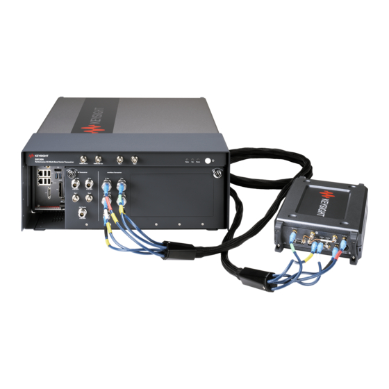
Page 53: Cable Connections
Exterior Features Cable Connections Cable Connections The right side of the diagram below shows cable connections from the front panel of the PXIe Subsystem to the M1741A, with cable part numbers. The left side shows connections from the instruments of the PXIe rack to the front panel of the PXIe Subsystem, again with cable part numbers. - Page 54 Exterior Features Cable Connections Getting Started Guide...
-
Page 55: User Interface
S9130A Performance 5G Multi-band Vector Transceiver Getting Started Guide 4 User Interface This is a basic introduction to the S9130A’s user interface. The following topics can be found in this section: Launching the Measurement Software on page 56 Screen Interface on page 58... -
Page 56: Launching The Measurement Software
User Interface Launching the Measurement Software Launching the Measurement Software In the Windows Start menu, select LaunchModularTRX under the Keysight Modular Transceiver folder. Select the transceiver from the launch window (check the box), and click Run Selected.The measurement software begins to load, as illustrated below. - Page 57 User Interface Launching the Measurement Software An alternative method is to launch from the S9130A Service Manager window. In the Windows Start menu, select S9130A Service Manager under the Keysight Technologies folder. After the Service Manager loads, the measurement software begins to load, as illustrated below...
-
Page 58: Screen Interface
User Interface Screen Interface Screen Interface The overall appearance of the display interface is illustrated below. Different parts of it are discussed in more detail in the following sections. The Slot n indicator in the upper left corner of the window refers to the slot within the PXIe chassis where the vector transceiver is located. - Page 59 User Interface Screen Interface Elements of the interface are discussed in more detail in the following sections. Figure 4-4 Elements of the display interface Getting Started Guide...
-
Page 60: Screen Tabs
Mode/Meas/View dialog The Sequencer feature at the left side of the dialog is not related to List Sequencer mode (which is not available on the S9130A). This selection only determines how multiple measurement screens are displayed and updated. Getting Started Guide... -
Page 61: System Settings
User Interface Screen Interface System Settings Clicking the "gear" icon opens the System Settings dialog, which allows you to access various information screens and settings interfaces. The tabs on the left side let you access various configuration screens. Figure 4-7 System Settings The System Settings screens include: —... -
Page 62: Preset
User Interface Screen Interface Preset Clicking this icon opens a menu which provides access to the various ways in which settings can be restored to a default condition or a condition you defined earlier. Figure 4-8 Preset Getting Started Guide... -
Page 63: Meas Bar
User Interface Screen Interface Meas Bar This bar displays important settings for the measurement, in a series of annotation panels which can be clicked on to reveal menu choices for them. The panel at the far left, for example, allows you to toggle between continuous and single measurement modes, and also to restart or pause a measurement. -
Page 64: Menu Panel
User Interface Screen Interface Menu Panel Clicking on the name at the top of the menu offers the available menus (Amplitude, BW, and so on) for selection. The selected menu is usually divided into separate sub-menus, any of which can be selected by clicking on the tabs to the right (for example, the tabs on the right of the Amplitude menu represent the Y Scale and Range sub-menus). -
Page 65: Measurement Display
User Interface Screen Interface Measurement Display The interface is centered around the display windows, which show the results of a measurement. The number of windows and the type of information displayed in them varies from measurement to measurement. For example, the Channel Power measurement example below shows a spectrum display and a table of numerical data. -
Page 66: Control Bar
User Interface Screen Interface Control Bar This provides controls and information displays related to various instrument functions that are independent of the current measurement. Figure 4-12 Control Bar Getting Started Guide... -
Page 67: Minimized Window
User Interface Screen Interface Minimized window A minimized window can be brought back up by finding the icon representing it in the Windows taskbar. Although the graphics for any two Keysight applications may look alike (as in the illustration below), hovering the mouse over one of them will display its Slot number and a small graphic representation of its measurement screen. -
Page 68: Help System
User Interface Screen Interface Help System Detailed information about all features of the test software is available from the help system. To open the help content for the mode currently running, click the question-mark icon at the bottom of the screen. Because menus and features differ between (for example) the WLAN mode and the 5GNR mode, separate help systems for these modes are installed on the system. - Page 69 User Interface Screen Interface Context-sensitive help To access information about a particular feature of the user interface, right-click on that feature; a popup menu appears which shows Help on this setting as a selection. This selection opens the help content to a page which is specific to that feature.
-
Page 70: Command Interface
User Interface Command Interface Command Interface In addition to being controlled and monitored by way of the screen interface, the instrument can be controlled and monitored by means of SCPI commands. For example, averaging can be disabled for the ACP measurement screen by changing the Averaging setting to Off in the Meas Setup >... - Page 71 User Interface Command Interface To take another example, the command which sets the measurement center frequency has the following syntax: [:SENSe]:FREQuency:CENTer <freq> This command can be sent in its long form: :SENSe:FREQuency:CENTer 16 GHz However, it can also be shortened to: :FREQ:CENT 16 GHz There is not always a command equivalent for a function of the screen interface (some functions which relate only to the display do not need a command).
- Page 72 User Interface Command Interface Getting Started Guide...
-
Page 73: Operating Tasks
Keysight Wireless Solutions S9130A Performance 5G Multi-band Vector Transceiver Getting Started Guide 5 Operating Tasks The following topics can be found in this section: “Receiver Setup” on page 74 “Source Setup” on page 79 “Port Configuration” on page 82 “Alignments” on page 91 “LAN Address Configuration”... -
Page 74: Receiver Setup
Operating Tasks Receiver Setup Receiver Setup The analyzer/receiver function of the S9130A relates to measurement of signals received from the DUT. Clicking on the measurement tab at the upper left corner of the display opens the Mode/Measurement/View Selector, which you can use to select a particular kind of measurement. - Page 75 Operating Tasks Receiver Setup Most measurement settings are made from the menus, which can be accessed by selecting the dropdown button near the upper right of the display. Figure 5-2 Accessing Menus Selecting a menu from the dropdown list displays the menu selections (usually the selections are indented under multiple tabs shown at the right).
- Page 76 Operating Tasks Receiver Setup For example, the Amplitude menu has three tabs; the selections under the Y Scale and Range tabs are shown below. Figure 5-3 Measurement Menus Getting Started Guide...
- Page 77 Operating Tasks Receiver Setup Although some menu choices involve only a simple selection (On | Off) or a value to be entered (17 GHz), some choices cause a more elaborate selection screen to appear in the display. In the example illustrated below, Trigger > Trigger Settings Diagram opens an interactive display (the trigger source can be changed from Free Run to Ext 1 by clicking on the graphic).
- Page 78 Operating Tasks Receiver Setup Another type of complex screen which some menu selections open is a configuration window such as the Meas Setup Summary Table, which gathers together multiple settings on one screen to make it easier to review them. Figure 5-5 Meas Setup Summary Table The menu choices are different for each measurement.
-
Page 79: Source Setup
Operating Tasks Source Setup Source Setup The source function of the S9130A relates to generation of test signals to be transmitted to the DUT. (Not all measurement scenarios require these signals, but many do.) Most source settings are made from the Input/Output > RF Source menu, illustrated below. - Page 80 Operating Tasks Source Setup Figure 5-7 ARB Setup Window The source employs a user-defined waveform file for modulation (typically such a file would be created in Keysight Signal Studio software). To load a waveform file that is saved in a location on the disk drive, click the File icon at the bottom of the screen, and click the Recall icon which appears.
- Page 81 Operating Tasks Source Setup Figure 5-8 Recalling an ARB file For more detailed information about source setup, see the help file for the 5G application. Getting Started Guide...
-
Page 82: Port Configuration
Operating Tasks Port Configuration Port Configuration The diagram below shows the names of ports, as they appear on the front panel (black titles), and also as they are named in the user interface (blue titles) and in the SCPI commands (red titles). Figure 5-9 Port nomenclature (in labels, menus, &... -
Page 83: Port Selection
RF Output Port dropdown list. — RF Output means the PXIe subsystem RF Out port. This port is in the lower (RF) frequency range of the S9130A. — RFIO HD means the PXIe subsystem Half Duplex port. - Page 84 RF Input Port dropdown list. — RF Input means the PXIe subsystem RF In port. This port is in the lower (RF) frequency range of the S9130A. — RFIO HD means the PXIe subsystem Half Duplex port.
- Page 85 Operating Tasks Port Configuration "Output" menu Two settings are visible on the menu Input/Output > Output menu (REF Output and LO Output). These actually relate to signals within the PXIe Subsystem, and are not used in connection with features that are currently available.
-
Page 86: Configuration Examples (Rf Range Only)
Operating Tasks Port Configuration Configuration examples (RF range only) In the examples that follow, only the lower (RF) range of the S9130A is used. Figure 5-13 Example: RF Out and RF In ports Set up the RF Input using this menu setting or its equivalent command: Input/Output >... - Page 87 It cannot be used for both at the same time. However, in cases where the S9130A is connected to a DUT with a single RF I/O port, using the Half Duplex port makes it unnecessary to change the cable connection when switching from output to input.
-
Page 88: Configuration Example (Mmwave Range Only)
Operating Tasks Port Configuration Configuration example (mmWave range only) In the example below, only the upper (mmWave) range of the S9130A is used. Figure 5-15 Example: M1741A transceiver Set up the RF Input using this menu setting or its equivalent command: Input/Output >... -
Page 89: Configuration Examples (Rf And Mmwave Ranges)
Port Configuration Configuration examples (RF and mmWave ranges) Both the lower range (RF) and upper range (mmWave) of the S9130A can be used at once. In the example below, the RF Out port is the transmit port (the Half Duplex port could also have been used), and one of the RF Tx/Rx ports on the M1741A is the receive port (it could be either one). - Page 90 Operating Tasks Port Configuration In the example below, the RF In port is the receive port (the Half Duplex port could also have been used), and one of the RF Tx/Rx ports on the M1741A is the transmit port (it could be either one). Figure 5-17 Example: Using both ranges (RF Rx, mmWave Tx) Set up the RF Input using this menu setting or its equivalent command:...
-
Page 91: Alignments
Operating Tasks Alignments Alignments Alignments are internal calibration adjustments which the transceiver must make to ensure that internal signal levels are properly maintained. Alignments menu To avoid interruptions, the alignments are not run automatically, either at startup or afterward; you must run them explicitly, using the Alignments menu (or sending equivalent SCPI commands). -
Page 92: Comparing Alignment Types
Operating Tasks Alignments Comparing alignment types The color-coded illustration below shows which parts of the system are covered by different alignment types. Figure 5-19 Types of alignment The standard Align Now All option (blue in the illustration) is for internal alignment of the PXIe subsystem;... - Page 93 Operating Tasks Alignments The remaining three alignments pertain to the M1741A remote radio head transceiver. (These make use of RF sensors within the PXIe Subsystem and the M1741A; connection of external measurement devices is not required.) Align IF Cable (red in the illustration on the previous page) includes the IF cables from the mmW Transceiver section front panel of the PXIe Subsystem to the instrument-facing side of the M1741A transceiver;...
-
Page 94: Align Now All
Operating Tasks Alignments Align Now All This alignment of the source and analyzer in the PXIe Subsystem is sufficient to maintain specified performance of that subsystem, provided that (1) the PXIe Subsytem’s internal temperature has not drifted more than 5 degrees C since the previous "All"... -
Page 95: Align If Cable
Operating Tasks Alignments Align IF Cable This alignment includes the IF cables from the front panel of the PXIe Subsystem to the instrument-facing side of the M1741A remote radio head transceiver; it assures proper signal levels at the Tx IF In and RX IF Out ports of the M1741A. -
Page 96: Align External Mixer Path
Operating Tasks Alignments Align External Mixer Path This is a subset of Align Now All; it assures proper signal levels at the mmW Transceiver ports which interface with the remote radio head (M1741A). This alignment typically takes about 2 minutes to run. This alignment can be used as a quicker substitute for Align Now All, but only for measurements using the mmWave Transceiver ports and not the RF Transceiver ports. -
Page 97: Align High Band
Operating Tasks Alignments Align High Band This is a subset of Align Now All; it assures proper signal levels at the RF Transceiver ports, for frequencies at or above 4.3 GHz. This alignment typically takes about 11 minutes to run. This alignment can be used as a quicker substitute for Align Now All, but only for measurements using the RF Transceiver ports rather than the mmWave Transceiver ports, and only at frequencies at or above 4.3 GHz. -
Page 98: Align Low Band
Operating Tasks Alignments Align Low Band This is a subset of Align Now All; it assures proper signal levels at the RF Transceiver ports, for frequencies below 4.3 GHz. This alignment typically takes about 16 minutes to run. This alignment can be used as a quicker substitute for Align Now All, but only for measurements using the RF Transceiver ports rather than the mmWave Transceiver ports, and only at frequencies below 4.3 GHz. -
Page 99: Align Rrh Amplitude
Operating Tasks Alignments Align RRH Amplitude This alignment includes all switched signal paths through the M1741A transceiver; it assures proper signal levels at the RF Tx/Rx ports on the DUT-facing side of the M1741A. The alignment typically takes about 25 minutes to run. -
Page 100: Checking Temperature And Status
Operating Tasks Alignments Checking Temperature and Status The PXIe subsystem’s internal temperature and the time since the most recent alignment can be checked by selecting System Settings> Alignments > Show Alignment Statistics, as illustrated below. Figure 5-26 Show Alignment Statistics Getting Started Guide... -
Page 101: Lan Address Configuration
Operating Tasks LAN Address Configuration LAN Address Configuration The S9130A supports both dynamic and static assignment of its IP address, using ports LAN 1 and LAN 2. The LAN 1 port is designed for dynamic IP addressing, using the Dynamic Host Configuration Protocol. -
Page 102: Configuring The Lan
If you cannot easily obtain a monitor view of System > Show > System, you can determine the computer name using the instrument serial number. The computer name is in the format K-S9130A-nnnnn, ending in the last five digits of the serial number. -
Page 103: Managing Licenses
Operating Tasks Managing Licenses Managing Licenses Licenses can be tied to a particular instrument, or transferable from one instrument to another by various means. Licenses can be either time-based or perpetual (the latter have no expiration date). To verify which licenses are installed, open the Keysight License Manager from the Windows Start menu. -
Page 104: Node-Locked License
Operating Tasks Managing Licenses Node-locked License A node-locked license is a license which permits the licensed software to run on one particular machine. Each node-locked license is locked to an instrument or computer; the license is resident on the hard disk of the system it is locked to, and that system runs the licensed feature or product. -
Page 105: Usb-Portable License
(Select Help > Keysight License Manager Help and search for “transport” to find detailed instructions.) Transportable licenses for the S9130A allow you to transport licenses up to 30 times within 10 days. Other related topics for managing your software and licenses can be found by reviewing the Keysight License Manager Help available by clicking "?"... -
Page 106: Floating License
Operating Tasks Managing Licenses Floating License A floating license (sometimes referred to as a network license) is another type of transferable license, in which the license is assigned temporarily by a designated license server. Setup your license server by installing Keysight License Manager 6. -
Page 107: System Components
Keysight Wireless Solutions S9130A Performance 5G Multi-band Vector Transceiver Getting Started Guide 6 System Components The following topics can be found in this section: “PXIe Subsystem” on page 108 “mmWave Transceiver” on page 109 “RF Transceiver” on page 110 “Extended System” on page 111... -
Page 108: Pxie Subsystem
The diagram below shows the instruments in the PXIe subsystem, and shows how they interface with the M1741A, an RF DUT, and a mmWave DUT. Path switching and frequency setting are under the control of the test application software which the S9130A is running. Figure 6-1 PXIe subsystem... -
Page 109: Mmwave Transceiver
DUT, depending on how the switches are set. (However, when one port transmits, the other must receive.) Path switching and LO frequency setting are controlled by the test application software which the S9130A is running. Getting Started Guide... -
Page 110: Rf Transceiver
(though not both at once). These ports are controlled by the test application software which is running on the S9130A. Each of the Trig 1 and Trig 2 ports can be used as a source marker output, an analyzer trigger input or output, or a source trigger input or output. -
Page 111: Extended System
System Components Extended System Extended System The diagram below provides an all-inclusive view of paths through the S9130A system. Figure 6-4 Extended system diagram Getting Started Guide... -
Page 112: Pxie System Controller
System Components PXIe System Controller PXIe System Controller Normally, the PXIe subsystem includes an M9037A Controller. However, some customers may choose to customize the system, to substitute a PC for this controller (typically because of a need for features or performance not supported by the M9037A itself). -
Page 113: Troubleshooting
Getting Started Guide 7 Troubleshooting The following topics can be found in this section: “Basic Operational Check” on page 114 “Identifying Problems” on page 120 “Where to get technical help” on page 121 “Returning the S9130A for Service” on page 122... -
Page 114: Basic Operational Check
Troubleshooting Basic Operational Check Basic Operational Check This procedure can be used to establish proper functioning of the system, or to identify specific areas in which there is a problem. Step 1. Attach a loop-back cable between the ports RF Tx/Rx 1 and RF Tx/Rx 2 on the M1741A remote radio head. - Page 115 Troubleshooting Basic Operational Check Step 2. Launch the measurement application. Figure 7-2 Launching the application The application begins with an IQ analayzer measurement window displayed. Figure 7-3 Measurement window at startup Getting Started Guide...
- Page 116 Troubleshooting Basic Operational Check Step 3. Select RF Output and RF Input ports. In this procedure the M1741A remote radio head is used, so the Head 1 ports need to be used. These settings can be set from the Input/Output menu, but a quicker method is to click on the Input/Output column at the top of the measurement screen to open a menu below it.
- Page 117 Troubleshooting Basic Operational Check Step 4. Set the source and measurement frequencies. Go to Input/Ouptut > RF Source and set Frequency to 28.0 GHz. This is the output (source) frequency. Go to the Frequency menu and set Center Frequency to 28.0 GHz. This is the input (measurement) frequency.
- Page 118 Troubleshooting Basic Operational Check Step 6. Set up power & modulation for the source. Go to Input/Output > RF Source. Set RF Output to On. Set RF Power to 0 dBm. Figure 7-7 Setting source power/modulation Getting Started Guide...
- Page 119 Troubleshooting Basic Operational Check Step 7. Verify received signal power. With RF Output set to On, you should see a signal on the display corresponding to the frequency and power level that were set. (Although the frequency should be an exact match, cable loss will cause the received signal to show a slightly lower power level than was set for the transmitted signal.) If you don’t see this signal, make sure that both the input and output are set to the same frequency (28 GHz).
-
Page 120: Identifying Problems
If the status indicator on the M1741A is not lit, or if it appears that mmWave signals are not being exchanged with the Device Under Test check the following: 1. Are the RF cables connected appropriately between the S9130A and the measurement instrument? (See “Cable Connections” on page 53.) -
Page 121: Where To Get Technical Help
Troubleshooting Where to get technical help Where to get technical help For online assistance: http://www.keysight.com/find/assist To contact Keysight Technologies: http://www.keysight.com/find/contactus Also, see “Locations for Keysight Technologies” on page 123. Getting Started Guide... -
Page 122: Returning The S9130A For Service
Calling Keysight Technologies Keysight Technologies has offices around the world to provide you with complete support for the S9130A. To obtain servicing information, or to order replacement parts, contact the nearest Keysight Technologies office listed under “Locations for Keysight Technologies” on page 123. -
Page 123: Locations For Keysight Technologies
Troubleshooting Returning the S9130A for Service Locations for Keysight Technologies For online assistance: http://www.keysight.com/find/assist To contact Keysight Technologies: http://www.keysight.com/find/contactus Alternately, contact the nearest Keysight sales office: Americas Canada Brazil Mexico (877) 894 4414 55 11 3351 7010 001 800 254 2440... - Page 124 This information is subject to change without notice. © Keysight Technologies 2020 Edition 1, November 2020 S9130-90001 www.keysight.com...
Need help?
Do you have a question about the S9130A and is the answer not in the manual?
Questions and answers