
Related Manuals for Keysight Technologies M1749B


Summary of Contents for Keysight Technologies M1749B
- Page 1 Keysight mmWave Reference Solutions M1749B Performance mmWave Transceiver 22.7 - 49 GHz Getting Started Guide...
- Page 2 THESE TERMS, THE WARRANTY beyond those set forth in the TERMS IN THE SEPARATE EULA shall apply, except to the © Keysight Technologies, Inc. 2022 AGREEMENT WILL CONTROL. extent that those terms, rights, or No part of this manual may be...
- Page 3 For product specific information and support, software and documentation updates: http://www.keysight.com/find/m1749b Worldwide contact information for repair and service: http://www.keysight.com/find/assist To contact Keysight Technologies: http://www.keysight.com/find/contactus To receive the latest updates by email, subscribe to Keysight Email Updates at the following URL: http://www.keysight.com/find/MyKeysight Information on preventing instrument damage can be found at: www.keysight.com/find/PreventingInstrumentRepair...
-
Page 5: Table Of Contents
Contents Table of Contents Safety & Environmental Information 7 Warning Statements and Symbols 8 Safety 9 Safety Compliance 9 Safe Installation 9 Acoustic statement (European Machinery Directive) 9 General Safety Notices 9 Environmental Conditions (Operating) 10 Environmental Information 10 EMC (Electromagnetic Compatibility) 11 South Korean Class A EMC declaration 11 Declaration of Conformity 11 Ventilation 12... - Page 6 Contents Signal Routing 35 Control 37 Troubleshooting 39 Where to get technical help 40 Identifying Problems 40 Returning the M1749B for Service 41 Calling Keysight Technologies 41 Locations for Keysight Technologies 42 Getting Started Guide...
-
Page 7: Safety & Environmental Information
Keysight Wireless Test Set M1749B Performance mmWave Transceiver Getting Started Guide Safety & Environmental Information The following topics can be found in this section: “Warning Statements and Symbols” on page 8 “Safety” on page 9 “Environmental Conditions (Operating)” on page 10 “EMC (Electromagnetic Compatibility)”... -
Page 8: Warning Statements And Symbols
Safety & Environmental Information Warning Statements and Symbols Warning Statements and Symbols Caution and Warning notices are used in this document are described below. A CAUTION notice denotes a hazard. It calls attention to an operating procedure, practice, or the like that, if not correctly performed or adhered to, could result in damage to the product or loss of important data. -
Page 9: Safety
Safety & Environmental Information Safety Safety This product has been designed and tested in accordance with accepted industry standards, and has been supplied in a safe condition.The documentation contains information and warnings that must be followed by the user to ensure safe operation and to maintain the product in a safe condition. -
Page 10: Environmental Conditions (Operating)
Safety & Environmental Information Environmental Conditions (Operating) Environmental Conditions (Operating) This product is designed for use in the following conditions: — For indoor use only — Altitude up to 3000 m — Temperature 10 to 40°C — Maximum relative humidity 95% (non-condensing) This product is designed for use in INSTALLATION CATEGORY II and POLLUTION DEGREE 2, per IEC 61010-1 Third Edition and 664 respectively. -
Page 11: Emc (Electromagnetic Compatibility)
Ambient continuous electromagnetic phenomena between 2.3 and 4.1 GHz may appear at up to 55 dB above DANL using the M1749B Tx/Rx ports. South Korean Class A EMC declaration This equipment has been conformity assessed for use in business environments. -
Page 12: Ventilation
Safety & Environmental Information Ventilation Ventilation VENTILATION REQUIREMENTS: When installing the instrument(s) into a cabinet, consideration shall be given to the convection flow into and out of the cabinet. Consideration shall also be given to the individual instruments to avoid having the heated discharge of one instrument, now becoming the cooling intake air for another instrument. -
Page 13: Power Requirements
DC input from an AC/DC converter. This input does not represent a risk of personal injury. Do not remove the DC input plug from the M1749B while it is in an active state. Make sure the Status LED on the DUT-facing side of the M1749B is dark before disconnecting the DC input. -
Page 14: Weight And Dimensions
Safety & Environmental Information Weight and Dimensions Weight and Dimensions The weight and dimensions of the M1749B are as follows. — Weight: 3.5 kg — Height: 70 mm — Width: 175 mm — Length: 345 mm Protecting against electrostatic discharge... -
Page 15: Instrument Maintenance
Safety & Environmental Information Instrument Maintenance Instrument Maintenance Cleaning the Instrument Disconnect the M1749B from all cables before cleaning. Use a dry cloth or one slightly dampened with water to clean the external case parts. Do not attempt to clean internally. Connector Care... -
Page 16: Connector Cleaning
Safety & Environmental Information Instrument Maintenance Connector Cleaning Cleaning connectors with isopropyl alcohol shall only be done with all cables disconnected, and in a well-ventilated area. Allow all residual alcohol moisture to evaporate, and the fumes to dissipate prior to energizing the instrument. Keep isopropyl alcohol away from heat, sparks, and flame. -
Page 17: Quick Start
Keysight Wireless Test Set M1749B Performance mmWave Transceiver Getting Started Guide 2 Quick Start The following topics can be found in this section: “Purpose and Function” on page 18 “Initial Inspection” on page 20 “Location and Mounting” on page 21... -
Page 18: Purpose And Function
Figure 2-1 M1749B used as an RF/mmWave interface On the left side of the M1749B in the diagram, the Tx IF In port takes an input from the test system and upconverts it to the higher range of the DUT. Signals received from the DUT are downconverted and returned to the test system from the Rx IF Out port. - Page 19 USB controller and trigger lines shown in the illustration. The supplied AC/DC adapter provides a 19 VDC power input to the M1749B (this can also be done by a DC power supply, if one is included in the system steup).
-
Page 20: Initial Inspection
— Contact the nearest Keysight Technologies office. — Keep the shipping materials for the carrier’s inspection. — If you must return a test set to Keysight Technologies, use the undamaged original or comparable shipping materials. See “Returning the M1749B for Service”... -
Page 21: Location And Mounting
Quick Start Location and Mounting Location and Mounting It is recommended to suspend the transceiver above the Device Under Test (DUT), with the mmWave port pointed downwards at the DUT, so that heat given off by the transceiver will rise away from the DUT. Leave a minimum clearance of 2.5 inches (7 cm) around the transceiver. - Page 22 Quick Start Location and Mounting Getting Started Guide...
-
Page 23: Exterior Features
Keysight Wireless Test Set M1749B Performance mmWave Transceiver Getting Started Guide 3 Exterior Features The following topics can be found in this section: “DUT-Facing Side” on page 24 “Instrument-Facing Side” on page 26 “Labels and Symbols” on page 29... -
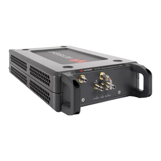
Page 24: Dut-Facing Side
Figure 3-1 M1749B, DUT-facing side The DUT-facing ports are shown on the right in the block diagram below. Figure 3-2 M1749B, DUT-facing ports (on right) The features of this side of the M1749B are illustrated and described on the following page. Getting Started Guide... - Page 25 These LEDs are lit when the named port is in use. RF Tx/Rx 2 Status This LED is lit to indicate that the M1749B is in an active state (this is determined by inputs received at the Control port on the instrument-facing side of the M1749B). Getting Started Guide...
-
Page 26: Instrument-Facing Side
Exterior Features Instrument-Facing Side Instrument-Facing Side The photograph below shows the instrument-facing side of the M1749B; the block diagram shows the instrument-facing RF ports (on the left). Figure 3-4 M1749B, instrument-facing side Figure 3-5 M1749B, instrument-facing ports (on left) Getting Started Guide... - Page 27 These SMB connectors carry trigger inputs and output to the external controller. These ports are Trig 2 required if the M1749B is controlled by way of the USB port. They are not required if the M1749B is controlled by way of the Control port, which incorporates trigger signals (however, Trig 1 even if the Control port is used, these trigger ports remain available for use).
- Page 28 This 3.5 mm connector accepts a variable-frequency input from the LO Out connector on the LO In front panel. This input is mixed with another input to the M1749B (9.6 GHz In) to generate the (see Caution below) LO input to the Transmitter Upconverter and the Receiver Downconverter. Torque wrench required.
-
Page 29: Labels And Symbols
Exterior Features Labels and Symbols Labels and Symbols Figure 3-7 M1749B regulatory labels Labels and symbols which may be shown on the M1749B (mainly on the rear panel of the chassis) are described in the table below. Symbol Description This symbol marks the standby position of the power line switch. - Page 30 Exterior Features Labels and Symbols Symbol Description The instruction documentation symbol. The product is marked with this symbol when it is necessary for the user to refer to the instruction in the documentation. This symbol indicates the presence of a laser device. This symbol indicates that the surface can be hot.
- Page 31 Exterior Features Labels and Symbols Symbol Description South Korean Certification (KC) mark. It includes the marking’s identifier code. The crossed-out wheeled bin symbol indicates that separate collection for waste electric and electronic equipment (WEEE) is required, as obligated by the EU DIRECTIVE and other National legislation. Please refer to www.keysight.com/go/takeback for information about your trade-in options with Keysight, in addition to product takeback instructions.
- Page 32 Exterior Features Labels and Symbols Getting Started Guide...
-
Page 33: Functionality
Keysight Wireless Test Set M1749B Performance mmWave Transceiver Getting Started Guide 4 Functionality The following topics can be found in this section: “Simplified Block Diagram” on page 34 “Signal Routing” on page 35 “Control” on page 37... -
Page 34: Simplified Block Diagram
Simplified Block Diagram The simplified functional block diagram below shows how signals to and from the S9130A system front panel (the left side of the M1749B in the illustration below) interface with the Tx upconverter and Rx downconverter, and how the upconverted and downconverted signals interface with the DUT-facing ports of the test head (the right side of the illustration). -
Page 35: Signal Routing
— Red: variable-frequency LO input to the M1749B, used in generating an LO input to the upconverter and downconverter. — Brown: fixed 9.6 GHz input to the M1749B, used in generating an LO input to the upconverter and downconverter. — Orange: generated LO signal to the upconverter and downconverter. - Page 36 Functionality Signal Routing The Tx/Rx ports are half-duplex: each one can function as a transmit port or a receive port (although not simultaneously). In the illustration below, the green transmit path can be routed either to RF Tx/Rx 1 (as in the upper picture) or to RF Tx/Rx 2 (as in the lower picture).
-
Page 37: Control
(source) port is designated in the application interface as Head 1 RFHD 1, this is equivalent to RF Tx/Rx 1 on the M1749B. In the diagram below, the port names are designated in blue (as they appear in the application interface menus) and also in red (as they are identified in SCPI commands.) - Page 38 Functionality Control Getting Started Guide...
-
Page 39: Troubleshooting
Keysight Wireless Test Set M1749B Performance mmWave Transceiver Getting Started Guide 5 Troubleshooting The following topics can be found in this section: “Identifying Problems” on page 40 “Returning the M1749B for Service” on page 41... -
Page 40: Where To Get Technical Help
No operator serviceable parts inside. Refer servicing to qualified personnel. To prevent electrical shock do not remove covers. If the status indicator on the M1749B is not lit, or if it appears that mmWave signals are not being exchanged with the Device Under Test check the following: 1. -
Page 41: Returning The M1749B For Service
Calling Keysight Technologies Keysight Technologies has offices around the world to provide you with complete support for the M1749B. To obtain servicing information, or to order replacement parts, contact the nearest Keysight Technologies office listed under “Locations for Keysight Technologies” on page 42. -
Page 42: Locations For Keysight Technologies
Troubleshooting Returning the M1749B for Service Locations for Keysight Technologies For online assistance: http://www.keysight.com/find/assist To contact Keysight Technologies: http://www.keysight.com/find/contactus Alternately, contact the nearest Keysight sales office: Americas Canada Brazil Mexico (877) 894 4414 55 11 3351 7010 001 800 254 2440... - Page 43 This information is subject to change without notice. © Keysight Technologies 2022 Edition 1, January 2022 M1749-90003 www.keysight.com...
Need help?
Do you have a question about the M1749B and is the answer not in the manual?
Questions and answers