Sign In
Upload
Manuals
Brands
WAGO Manuals
I/O Systems
750-531/000-800
WAGO 750-531/000-800 Output Module Manuals
Manuals and User Guides for WAGO 750-531/000-800 Output Module. We have
1
WAGO 750-531/000-800 Output Module manual available for free PDF download: Manual
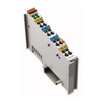
WAGO 750-531/000-800 Manual (54 pages)
4-Channel Digital Output Module 24 VDC; 2-Conductor Connection; Short-circuit-protected; Highside Switching
Brand:
WAGO
| Category:
I/O Systems
| Size: 2.4 MB
Table of Contents
Deutsch
3
Table of Contents
3
Table 1: Variants
5
Notes about this Documentation
5
Copyright
5
Validity of this Documentation
5
Symbols
6
Number Notation
8
Font Conventions
8
Table 2: Number Notation
8
Table 3: Font Conventions
8
Use of the WAGO-I/O-SYSTEM 750 in Compliance with Underlying Provisions
9
Personnel Qualifications
9
Subject to Changes
9
Legal Bases
9
Important Notes
9
Technical Condition of Specified Devices
10
Safety Advice (Precautions)
11
Device Description
13
View
15
Figure 1: View
15
Table 4: Legend for Figure "View
15
Figure 2: Data Contacts
16
Data Contacts/Internal Bus
16
Connectors
16
Table 5: Legend for Figure "Power Jumper Contacts
17
Figure 3: Power Jumper Contacts
17
Power Jumper Contacts/Field Supply
17
CAGE CLAMP ® Connectors
19
Figure 4: CAGE CLAMP ® Connectors
19
Table 6: Legend for Figure „CAGE CLAMP ® Connectors
19
Display Elements
20
Operating Elements
20
Figure 5: Display Elements
20
Table 7: Legend for Figure "Display Elements
20
Schematic Diagram
21
Figure 6: Schematic Diagram
21
Device Data
22
Power Supply
22
Communication
22
Outputs
22
Connection Type
22
Table 8: Technical Data - Device
22
Table 9: Technical Data - Power Supply
22
Table 10: Technical Data - Communication
22
Table 11: Technical Data - Inputs
22
Technical Data
22
Table 14: Technical Data - Data Contacts
23
Table 15: Technical Data - Climatic Environmental Conditions
23
Table 13: Technical Data - Power Jumper Contacts
23
Climatic Environmental Conditions
23
Approvals
24
Table 16: Ship Approvals
25
Standards and Guidelines
26
Mounting
27
Mounting Sequence
27
Inserting and Removing Devices
28
Inserting the I/O Module
28
Figure 7: Insert I/O Module (Example)
28
Figure 8: Snap the I/O Module into Place (Example)
28
Removing the I/O Module
29
Figure 9: Removing the I/O Module (Example)
29
Connect Devices
30
Connecting a Conductor to the CAGE CLAMP
30
Figure 10: Connecting a Conductor to a CAGE CLAMP
30
Connection Example
31
2-Conductor Connection
31
Figure 11: Connecting Diagram 2-Conductor Connection
31
Process Image
32
Table 17: Output Bits
32
Using Interference-Free Variants of I/O Modules in Safety Related Applications
33
Important Notes
34
Figure 12: Potential Group for Safety Related Applications
35
General Structure
35
Connecting the IO Module to Safety Switching Devices or Safety Modules
35
Examples of Connection
36
Figure 13: Two-Channel Single-Pole Disconnection
36
Figure 14: Two-Channel Double-Pole Disconnection
37
Use in Hazardous Environments
38
Marking Configuration Examples
39
Marking for Europe According to ATEX and IEC-Ex
39
Figure 15: Side Marking Example for Approved I/O Modules According to ATEX and Iecex
39
Figure 16: Text Detail - Marking Example for Approved I/O Modules According to ATEX and Iecex
39
Table 18: Description of Marking Example for Approved I/O Modules According to ATEX and Iecex
40
Table 20: Description of Marking Example for Approved I/O Modules According
40
Figure 18: Text Detail - Marking Example for Approved Ex I I/O Modules According to ATEX and Iecex
41
Figure 17: Side Marking Example for Approved Ex I I/O Modules According to ATEX and Iecex
41
Table 19: Description of Marking Example for Approved Ex I I/O Modules According to ATEX and Iecex
43
Marking for America According to NEC 500
44
Figure 19: Side Marking Example for I/O Modules According to NEC 500
44
Figure 20: Text Detail - Marking Example for Approved I/O Modules According
44
Installation Regulations
45
Special Conditions for Safe Use (ATEX Certificate TÜV 07 ATEX 554086 X)
46
Special Conditions for Safe Use (ATEX Certificate TÜV 12 ATEX 106032 X)
47
Special Conditions for Safe Use (IEC-Ex Certificate TUN 09.0001
48
Special Conditions for Safe Use (IEC-Ex Certificate Iecex TUN 12.0039 X)
49
Special Conditions for Safe Use According to ANSI/ISA
50
English
51
List of Figures
51
List of Tables
52
Advertisement
Advertisement
Related Products
WAGO 750-531
WAGO 750-530
WAGO 750-537
Wago 750-512
WAGO 750-585
WAGO I/O-SYSTEM 750-597
WAGO 750-562
WAGO 750-554
WAGO 750-556/000-200
WAGO 750-540
WAGO Categories
I/O Systems
Control Unit
Power Supply
Switch
Controller
More WAGO Manuals
Login
Sign In
OR
Sign in with Facebook
Sign in with Google
Upload manual
Upload from disk
Upload from URL