Siemens SITRANS LR460 Operating Instructions Manual
Radar transmitters
Hide thumbs
Also See for SITRANS LR460:
- Quick start manual (197 pages) ,
- Operating instructions manual (155 pages) ,
- Instruction manual (123 pages)
Table of Contents
Advertisement
Quick Links
SITRANS LR460
SITRANS L
Radar transmitters
SITRANS LR460
Operating Instructions
7ML5426 (LR460)
10/2021
A5E42035355-AB
Introduction
Safety notes
Description
Installing/mounting
Connecting
Commissioning
Remote operation
Parameter assignment
Service and maintenance
Troubleshooting
Technical specifications
Dimension drawing
Technical reference
HART communications
HART information structure
Communications via
PROFIBUS PA
PROFIBUS PA profile
structure
Local operation interface
LCD menu structure
List of abbreviations
Product documentation and
support
1
2
3
4
5
6
7
8
9
10
11
12
A
B
C
D
E
F
G
H
I
Advertisement
Table of Contents

Subscribe to Our Youtube Channel
Related Manuals for Siemens SITRANS LR460


Summary of Contents for Siemens SITRANS LR460
- Page 1 SITRANS LR460 Introduction Safety notes Description SITRANS L Installing/mounting Connecting Radar transmitters SITRANS LR460 Commissioning Remote operation Parameter assignment Operating Instructions Service and maintenance Troubleshooting Technical specifications Dimension drawing Technical reference HART communications HART information structure Communications via PROFIBUS PA...
- Page 2 Note the following: WARNING Siemens products may only be used for the applications described in the catalog and in the relevant technical documentation. If products and components from other manufacturers are used, these must be recommended or approved by Siemens. Proper transport, storage, installation, assembly, commissioning, operation and maintenance are required to ensure that the products operate safely and without any problems.
-
Page 3: Table Of Contents
Canadian Installations only: Industry Canada (IC) rules ............15 Safety notes........................16 2.8.1 Safety marking symbols ..................... 17 Description ............................18 SITRANS LR460 ........................18 Installing/mounting ..........................19 Installation location requirements ..................19 Mounting location ......................20 Nozzle design ........................21 Nozzle location ........................ - Page 4 Level application example ....................54 6.2.11 Auto false echo suppression ....................55 Remote operation ..........................56 Operating SITRANS LR460 via SIMATIC PDM ............... 56 Echo profile saving and viewing ..................57 Trend diagram (Level Trend over Time) ................58 Manual TVT shaper ......................59 Accessing functions in PDM ....................
- Page 5 Remaining sensor lifetime (SNS REMLIF) (6.2.) ..............109 8.7.3 Service interval (SERVICE) (6.3.) ..................112 Condensed status setup (COND SETUP) PROFIBUS PA only (7.) .......... 114 8.8.1 Condensed status setup (COND SETUP)(Profibus PA only) (7.) ........... 114 SITRANS LR460 Operating Instructions, 10/2021, A5E42035355-AB...
- Page 6 Auto false echo suppression ..................... 134 A.4.3 Near range (blanking) ...................... 134 A.4.4 Echo confidence ......................134 A.4.5 Fail-safe mode ......................... 135 Maximum process temperature chart ................136 HART communications........................138 HART communication ...................... 138 SITRANS LR460 Operating Instructions, 10/2021, A5E42035355-AB...
- Page 7 Handheld programmer: key functions in RUN mode ............168 Programming via the handheld programmer ..............169 Handheld programmer: key functions in Navigation mode ..........170 Handheld programmer: key functions in Edit mode ............170 SITRANS LR460 Operating Instructions, 10/2021, A5E42035355-AB...
- Page 8 LCD menu structure ........................... 172 LCD menu structure ......................172 List of abbreviations .......................... 177 Abbreviations ........................177 Product documentation and support ....................179 Product documentation ....................179 Technical support ......................180 Glossary ............................. 181 Index ..............................186 SITRANS LR460 Operating Instructions, 10/2021, A5E42035355-AB...
-
Page 9: Introduction
In order to use the device correctly, first review its principle of operation. The instructions are aimed at persons mechanically installing the device, connecting it electronically, configuring the parameters and commissioning it, as well as service and maintenance engineers. SITRANS LR460 Operating Instructions, 10/2021, A5E42035355-AB... -
Page 10: Fw Revision History
1.04.05 Jun. 29, 2007 New mA/HART hardware. 1.03.00-00 1.03.01-00 Jan. 12, 2007 Initial release. Designated use Use the device in accordance with the information on the nameplate and in the Technical specifications (Page 125). SITRANS LR460 Operating Instructions, 10/2021, A5E42035355-AB... -
Page 11: Security Information
Siemens’ products and solutions undergo continuous development to make them more secure. Siemens strongly recommends that product updates are applied as soon as they are available and that the latest product versions are used. Use of product versions that are no longer supported, and failure to apply the latest updates may increase customer’s exposure to... -
Page 12: Notes On Warranty
The sales contract contains all obligations on the part of Siemens as well as the complete and solely applicable warranty conditions. Any statements regarding device versions described in the manual do not create new warranties or modify the existing warranty. -
Page 13: Safety Notes
• National Electrical Code (NEC - NFPA 70) (USA) • Canadian Electrical Code (CEC Part I) (Canada) Further provisions for hazardous area applications are for example: • IEC 60079-14 (international) • EN 60079-14 (EU and UK) SITRANS LR460 Operating Instructions, 10/2021, A5E42035355-AB... -
Page 14: Conformity With European Directives
The Restriction of the Use of Certain Hazard- SI 2012/3032 ous Substances in Electrical and Electronic Equipment Regulations 2012 The applicable regulations can be found in the UKCA declaration of conformity of the specific device. SITRANS LR460 Operating Instructions, 10/2021, A5E42035355-AB... -
Page 15: Radio Equipment - Eu Directive (Red) 2014/53/Eu And Uk Regulation Si 2017/1206
Radio Equipment - EU Directive (RED) 2014/53/EU and UK regulation SI 2017/1206 Hereby, Siemens declares that the SITRANS LR460 is in compliance with the essential requirements and other relevant provisions of Directive 2014/53/EU. The LR460 complies with EN 302 372 for use in closed storage vessels, when installed according to the installation requirements of EN 302 372, and may be used in all EU countries. -
Page 16: Safety Notes
If you need additional information not covered by these instructions, contact your local Siemens office or company representative. Note Operation under special ambient conditions... -
Page 17: Safety Marking Symbols
If you have used the device outside the conditions for hazardous areas, make all Ex markings unrecognizable on the nameplate. 2.8.1 Safety marking symbols In manual On product Description WARNING: refer to accompanying documents (manual) for details. (Label on product: yellow back- ground.) SITRANS LR460 Operating Instructions, 10/2021, A5E42035355-AB... -
Page 18: Description
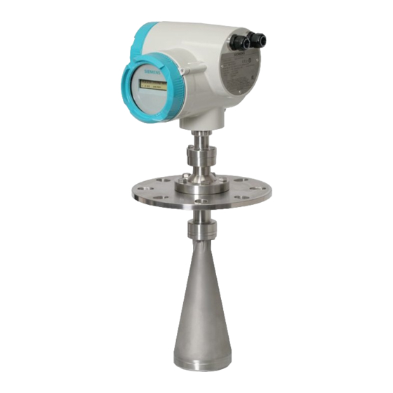
The high frequency signal creates a narrow emission cone, which makes the LR460 quite insensitive to vessel interferences. SITRANS LR460 is available with an optional air purge connection for cleaning the interior of the antenna. Programming SITRANS LR460 carries out its level measurement function according to the set of built-in parameter tables. -
Page 19: Installing/Mounting
• Make sure that the maximum permissible ambient temperature is not exceeded. Refer to the information in Technical specifications (Page 125). NOTICE Strong vibrations Damage to device. • In installations with strong vibrations, mount the transmitter in a low vibration environment. SITRANS LR460 Operating Instructions, 10/2021, A5E42035355-AB... -
Page 20: Mounting Location
• Provide an environment suitable to the housing rating and materials of construction. • Provide a sun shield if the device is mounted in direct sunlight. ① ambient temperature max. +65 °C (+149 °F) ② flange temperature ③ process temperature max. +200 °C (+392 °F) SITRANS LR460 Operating Instructions, 10/2021, A5E42035355-AB... -
Page 21: Nozzle Design
• Nozzle must allow adequate clearance to allow positioning if LR460 has to be at an angle so that emission cone perpendicular to material surface. ① Upper wave guide ② Factory lock screw ③ Min clearance: 10 mm (0.4") SITRANS LR460 Operating Instructions, 10/2021, A5E42035355-AB... -
Page 22: Nozzle Location
• Align the antenna so that the radar cone is perpendicular to the surface of the monitored material, if possible. See Easy Aimer installation (Page 24). • To compensate for vessels with obstructions, see also Installation in vessel with obstructions (Page 23). SITRANS LR460 Operating Instructions, 10/2021, A5E42035355-AB... -
Page 23: Installation In Vessel With Obstructions
Polarization Reference Point either faces towards the obstruction, or faces away from the obstruction (at 180 degrees). Tighten ball locking bolts when unit is in desired position. ① Polarization reference point ② Easy Aimer ball locking bolts SITRANS LR460 Operating Instructions, 10/2021, A5E42035355-AB... -
Page 24: Easy Aimer Installation
1. Holding the electronics enclosure firmly, loosen the Easy Aimer ball locking bolts and gently reposition the enclosure. 2. Direct SITRANS LR460 so the horn antenna is pointed at an angle perpendicular to the material surface, if possible. (As a guide, aim the beam at a point approximately 2/3 of the way across the tank diameter.) - Page 25 Installing/mounting 4.6 Easy Aimer installation ① Easy Aimer SITRANS LR460 Operating Instructions, 10/2021, A5E42035355-AB...
-
Page 26: Air Purging System (Optional)
• Some dust particles are highly abrasive and can be drawn into the inside of the horn during purge cleaning, damaging the internal PTFE emitter of the antenna. A replacement kit is available from your local Siemens representative. • It is the customer’s responsibility to ensure that any vacuum or pressure in the measured vessel is maintained, considering the hole that passes through the process connection and SITRANS LR460 antenna system. - Page 27 Installing/mounting 4.7 Air purging system (optional) ① Purged process connection with factory installed 1/8" NPT plug SCFM (standard cubic feet/minute) referenced to 14.7 psia, 68°F and 36% relative humidity (RH). SITRANS LR460 Operating Instructions, 10/2021, A5E42035355-AB...
-
Page 28: Universal Slotted Flange (For Use With Air Purging Option Only)
① Number of slotted bolt holes ② Bolt hole circle max. diameter ③ Bolt hole circle min. diameter ④ Flange O.D. ⑤ Thickness ⑥ Section "A-A" Slotted flange dimensions (see above) SITRANS LR460 Operating Instructions, 10/2021, A5E42035355-AB... -
Page 29: Optional Dust Cap
• It is particularly useful for applications in areas of high humidity, or with bulk solids with a high moisture content. • Two sizes are available, to fit the standard 3" and 4" horns. SITRANS LR460 Operating Instructions, 10/2021, A5E42035355-AB... - Page 30 3. Hand tighten the adjustable clamp supplied to secure the cap. 4. Use a screwdriver or nut driver to tighten the clamp screw until the clamp provides an air- tight seal. SITRANS LR460 Operating Instructions, 10/2021, A5E42035355-AB...
-
Page 31: Incorrect Disassembly
• If the device contains hazardous media, it must be emptied prior to disassembly. Make sure that no environmentally hazardous media are released. • Secure the remaining connections so that no damage can result if the process is started unintentionally. SITRANS LR460 Operating Instructions, 10/2021, A5E42035355-AB... -
Page 32: Connecting
Risk of explosion in hazardous areas as result of incorrect power supply. • Connect the device in accordance with the specified power supply and signal circuits. The relevant specifications can be found in the certificates, in Technical specifications (Page 125) or on the nameplate. SITRANS LR460 Operating Instructions, 10/2021, A5E42035355-AB... -
Page 33: Connecting Sitrans Lr460
Connecting 5.2 Connecting SITRANS LR460 Connecting SITRANS LR460 1. Release the cover lock on the enclosure with a 3 mm Allen key and unscrew the cover. (Use a screwdriver for extra leverage, if required.) 2. Loosen the cable gland and push the power cable through until it reaches the terminal strip. -
Page 34: Hart Wiring
Connecting 5.3 HART wiring HART wiring Note Power LR460 HART requires no power from the 4-20 mA loop. SITRANS LR460 Operating Instructions, 10/2021, A5E42035355-AB... -
Page 35: Connecting Hart
• Only one HART communication device should be inserted in the loop. ① PLC with mA input card ② PC/laptop with HART modem running PDM ③ HART communicator (Continued from Connecting SITRANS LR460 (Page 33)) SITRANS LR460 Operating Instructions, 10/2021, A5E42035355-AB... - Page 36 Use a cable with a cross-section of 2.5 mm or greater. ① Earth (ground) terminal ② Cable glands Full details about HART can be obtained from the HART Communication Foundation at Field comm group (www.fieldcommgroup.org). SITRANS LR460 Operating Instructions, 10/2021, A5E42035355-AB...
-
Page 37: Profibus Wiring
PROFIBUS PA MUST be terminated at both extreme ends of the cable for it to work properly. Please refer to the PROFIBUS PA User and Installation Guidelines (order number 2.092), available from www.profibus.com (www.profibus.com). AC version DC version ① Cable clamp ② Earth terminal SITRANS LR460 Operating Instructions, 10/2021, A5E42035355-AB... -
Page 38: Connecting Profibus Pa
5.6 Connecting PROFIBUS PA Connecting PROFIBUS PA Typical PLC/mA configuration with PROFIBUS PA (Continued from Connecting SITRANS LR460 (Page 33)) 1. Connect the earth conductor of the power supply to the earth terminal on the metal bracket inside the enclosure. Adjust the cable length so that the earth conductor would be last to disconnect if cable is pulled. -
Page 39: Product Nameplate
Use a cable with a cross-section of 2.5 mm or greater. ① Earth (ground) terminal ② Cable glands Product Nameplate Note A representative 'sample' of the configurable nameplate may have to generated for demonstration purposes. SITRANS LR460 Operating Instructions, 10/2021, A5E42035355-AB... -
Page 40: Instructions Specific To Hazardous Area Installations
9. It is the user’s responsibility to ensure that a manual override is possible in order to shut down the equipment, and that protective systems are incorporated within automatic processes which deviate from the intended operating conditions, provided that this does not compromise safety. SITRANS LR460 Operating Instructions, 10/2021, A5E42035355-AB... -
Page 41: Special Conditions For Safe Use
• The supply to the equipment shall be rated for a propective short circuit current of not more than 10KA and shall be protected by a suitably-rated fuse. SITRANS LR460 Operating Instructions, 10/2021, A5E42035355-AB... -
Page 42: Commissioning
Danger of poisoning when venting the device: if toxic process media are measured, toxic gases and liquids can be released. • Before venting ensure that there are no toxic gases or liquids in the device, or take the appropriate safety measures. SITRANS LR460 Operating Instructions, 10/2021, A5E42035355-AB... -
Page 43: Quick Start
6.2.2 Activating SITRANS LR460 Note • Keep infrared devices such as laptops, cell phones, and PDAs, away from SITRANS LR460 to prevent inadvertent operation. • Frequently switching the device off and on causes wear of the electronics. See Statistics (STATS) (2.3.) (Page 77) to access the records. -
Page 44: Run Mode Display
For more information, see Echo confidence (Page 134) Flashes once per second to indicate that the device is functioning. 6.2.4 Programming SITRANS LR460 Activate PROGRAM mode at any time, to change parameter values and set operating conditions. • Parameters are organized into function groups and arranged in a four-level menu structure (see LCD menu structure (Page 172)). -
Page 45: The Handheld Programmer And Program Mode Display
The handheld programmer and PROGRAM mode display Note For more detailed information on the programmer and the LCD display, see Local operation interface (Page 166) ① Display ② Max. 600 mm (2 ft) ③ Handheld programmer SITRANS LR460 Operating Instructions, 10/2021, A5E42035355-AB... -
Page 46: Quick Start Wizard Via The Handheld Programmer
4. To change a setting, scroll to the desired selection or key in a new value. 5. After modifying a value, press Right ARROW to accept it. The LCD displays the next menu item, the PROGRAM icon disappears, and the rightmost digit flashes to indicate Navigation Mode. SITRANS LR460 Operating Instructions, 10/2021, A5E42035355-AB... -
Page 47: Quick Start (1.)
Commissioning 6.2 Quick start 6.2.7 Quick start (1.) Language (1.1.) Options ENGLISH, DEUTSCH, FRANCAIS, ESPANOL SITRANS LR460 Operating Instructions, 10/2021, A5E42035355-AB... - Page 48 Distance to material surface referenced from Sensor Refer- ence Point. ① Low calibration point ② Level ③ High calibration point ④ Sensor reference point (flange face) ⑤ LR460 ⑥ High level point ⑦ Low level point SITRANS LR460 Operating Instructions, 10/2021, A5E42035355-AB...
-
Page 49: Quick Start Wizard Via Simatic Pdm
In order to save the Quick Start settings it is necessary to enable Apply Changes. Options YES, NO Select YES. SITRANS LR460 is now ready to operate and returns to RUN mode. 6.2.8 Quick start wizard via SIMATIC PDM The graphical Quick Start Wizard groups together all the settings you need to make for a simple application into 4 steps. - Page 50 3. Launch SIMATIC Manager and create a new project for LR460. Application Guides for setting up HART and PROFIBUS PA devices with SIMATIC PDM can be downloaded from the product page of our website at: Product page (www.siemens.com/lr460). 4. Open the menu Device – Reset and click on Factory Defaults and click OK.
-
Page 51: Quick Start Wizard Steps
Step 1 - Identification Click NEXT to accept default values. [Descriptor, Message, and Installation Date (Last config with HART device) fields can be left blank.] * Installation Date field appears as Last config with HART device. SITRANS LR460 Operating Instructions, 10/2021, A5E42035355-AB... - Page 52 Select the application type and operation type and click NEXT. Step 3 - Range setup Set Sensor Units, enter values for Low and High Calibration points, and select a Response Rate just faster than the maximum fill/empty rate. Click NEXT. SITRANS LR460 Operating Instructions, 10/2021, A5E42035355-AB...
- Page 53 * Installation Date field appears as Last config with HART device. After the values have been transferred to the device the message Device Configuration Complete appears. Click OK to upload values from the device to the PC/PG. and synchronize the device and PDM. SITRANS LR460 Operating Instructions, 10/2021, A5E42035355-AB...
-
Page 54: Level Application Example
Level Material level referenced from Low Calibration point. Units High calibration point Process full level. Low calibration point 15.5 Process empty level. Rate Slow Response rate = 0.1 m/minute. Apply changes Save new settings. SITRANS LR460 Operating Instructions, 10/2021, A5E42035355-AB... -
Page 55: Auto False Echo Suppression
6.2.11 Auto false echo suppression If SITRANS LR460 displays a false high level, or the reading is fluctuating between the correct level and a false high level, you can use the Auto False Echo Suppression parameters to prevent false echo detection. For instructions, see TVT (Auto false echo suppression) setup (3.5.6.) (Page 88). -
Page 56: Remote Operation
Remote operation Operating SITRANS LR460 via SIMATIC PDM SIMATIC PDM is a software package used to commission and maintain SITRANS LR460 and other process devices. Please consult the operating instructions or online help for details on using SIMATIC PDM. Functions in SIMATIC PDM SIMATIC PDM monitors the process values, alarms and status signals of the device. -
Page 57: Echo Profile Saving And Viewing
• Open the menu View – Echo Profile. • Press Measure to update an echo profile. • After saving a profile open menu View – Show echo profile. SITRANS LR460 Operating Instructions, 10/2021, A5E42035355-AB... -
Page 58: Trend Diagram (Level Trend Over Time)
Double click each axis and record the Xscale and Data Scale values, so that you can restore the default view by resetting to these values. Open the menu View – Trend to see the level trend over time. SITRANS LR460 Operating Instructions, 10/2021, A5E42035355-AB... -
Page 59: Manual Tvt Shaper
• Change the position of the X cursor on the TVT curve using the Index+ and Index– buttons: raise and lower the curve using Value+ and Value–. • Alternatively, enter values directly into the dialog boxes for each breakpoint. SITRANS LR460 Operating Instructions, 10/2021, A5E42035355-AB... -
Page 60: Accessing Functions In Pdm
For a complete list, see Pull-down menus for HART via SIMATIC PDM (Page 63) and Pull-down menus for PROFIBUS PA via SIMATIC PDM (Page 64). ① Pull-down menus Online display The online display allows you to compare outputs in real time. Open the menu View – Display. SITRANS LR460 Operating Instructions, 10/2021, A5E42035355-AB... -
Page 61: Changing Parameter Settings Via Simatic Pdm
For a complete list of parameters, see Parameter assignment (Page 67). 1. Launch SIMATIC PDM, connect to SITRANS LR460, and upload data from the device. 2. Adjust parameter values in the parameter value field then press Enter. The status fields read Changed. -
Page 62: Parameters Accessed Via Pull-Down Menus
2. Select Other, enter the new value, and click OK. The message ’Field Device fixed at new value’ appears. Click OK. 3. When you are ready to end simulation, select End and click OK to return the device to the original output level. SITRANS LR460 Operating Instructions, 10/2021, A5E42035355-AB... -
Page 63: Pull-Down Menus For Hart Via Simatic Pdm
TVT shaper Status bar Auto false echo suppression Maintenance Update Self test Reset Configuration flag reset D/A trim Write locking Simulate AO HART communication Simulation * Displays only if a profile has been saved SITRANS LR460 Operating Instructions, 10/2021, A5E42035355-AB... -
Page 64: Pull-Down Menus For Profibus Pa Via Simatic Pdm
Echo profile Update diagnostic status Show echo profile* Device status Clear faults Peak values Wear Set address Toolbar Status bar Quick start Update TVT shaper Auto false echo suppression Maintenance Reset Write locking Simulation SITRANS LR460 Operating Instructions, 10/2021, A5E42035355-AB... -
Page 65: Simulation
1. Open the menu Device – Simulation, and select the desired function block. 2. From the Simulation (Measured Value) tab, enable simulation, enter a value, and click Transfer. 3. After simulation is complete, disable simulation. SITRANS LR460 Operating Instructions, 10/2021, A5E42035355-AB... - Page 66 2. To enable simulation select Fixed or Ramp. If you select Ramp, enter the step length and number of steps. 3. Enter the simulated value and click Transfer. 4. After simulation is complete, disable simulation. SITRANS LR460 Operating Instructions, 10/2021, A5E42035355-AB...
-
Page 67: Parameter Assignment
• You can access the Quick Start wizard either via SIMATIC PDM, or via the handheld programmer. • Each time the Quick Start Wizard is initiated, the start-up settings are factory defaults. The Wizard will not recall previous user-defined settings. SITRANS LR460 Operating Instructions, 10/2021, A5E42035355-AB... -
Page 68: Quick Start (1.)
Parameter assignment 8.3 Quick start (1.) Quick start (1.) Language (1.1.) Options ENGLISH, DEUTSCH, FRANCAIS, ESPANOL SITRANS LR460 Operating Instructions, 10/2021, A5E42035355-AB... - Page 69 Distance to material surface referenced from Sensor Refer- ence Point. ① Low calibration point ② Level ③ High calibration point ④ Sensor reference point (flange face) ⑤ LR460 ⑥ High level point ⑦ Low level point SITRANS LR460 Operating Instructions, 10/2021, A5E42035355-AB...
- Page 70 Apply Changes (APPLY?) (1.8.) In order to save the Quick Start settings it is necessary to enable Apply Changes. Options YES, NO Select YES. SITRANS LR460 is now ready to operate and returns to RUN mode. SITRANS LR460 Operating Instructions, 10/2021, A5E42035355-AB...
-
Page 71: Identification (Ident) (2.)
• Press Down ARROW , Right ARROW , Right ARROW to navigate to Address. • Press Right ARROW to open Edit mode: the PROGRAM icon will flash. • If required, key in a new value and press Right ARROW to accept it. SITRANS LR460 Operating Instructions, 10/2021, A5E42035355-AB... - Page 72 NONE. 4. Press Mode to return to Measurement Mode. To perform a Reset via SIMATIC PDM: Open the menu Device – Reset, and select Factory Defaults or Warm Start. SITRANS LR460 Operating Instructions, 10/2021, A5E42035355-AB...
-
Page 73: Configuration (Config) (For Profibus Pa Devices) (2.1.)
2. Press Down ARROW , Right ARROW , Right ARROW to navigate to Address. 3. Press Right ARROW to open Edit mode: the PROGRAM icon will flash. 4. If required, key in a new value and press Right ARROW to accept it. SITRANS LR460 Operating Instructions, 10/2021, A5E42035355-AB... - Page 74 3. Press DOWN Arrow to scroll to the desired option from table above and RIGHT Arrow to select it. After the Reset is performed, the display will return to NONE. 4. Press Mode to return to Measurement Mode. SITRANS LR460 Operating Instructions, 10/2021, A5E42035355-AB...
-
Page 75: Device (2.2.)
References a specific manufacturer, usually the name of the company responsible for the manufacture of this Field Device. Product designation Uniquely identifies the Field Device when combined with the Manufacturer Identification and Device Type. This variable cannot be modified by the Host user. SITRANS LR460 Operating Instructions, 10/2021, A5E42035355-AB... - Page 76 Values Profile-specific [uses generic GSD for 2 AIFB (ident # = 0x9701)] Manufacturer-specific [uses Siemens DD and GSD file, which identifies the LR460 (PROFIBUS PA)] (ident # = 0x8132) Profile-specific [uses generic GSD for 1 AIFB (ident # = 0x9700)] Installation date (PROFIBUS PA);...
-
Page 77: Statistics (Stats) (2.3.)
Static revision number The revision level of the static data associated with the Level Transducer Block, updated whenever a configuration parameter is changed. Class Indicates the Level Transducer Block as per PROFIBUS PA Profile specifications. SITRANS LR460 Operating Instructions, 10/2021, A5E42035355-AB... -
Page 78: Standard Setup (St Setup) (3.2.)
Slower settings provide higher accuracy and a smoother output signal: faster settings allow for more level fluctuation. For instructions on usage, see "LOE Timer" in Echo confidence (Page 134). For technical details, see "LOE timer" in Fail-safe (3.5.1.) (Page 83). SITRANS LR460 Operating Instructions, 10/2021, A5E42035355-AB... -
Page 79: Sensor Calibration (Sensor Cal) (3.3.)
To perform calibration for a simple application, go to Quick start wizard via the handheld programmer (Page 46) or Quick start wizard via SIMATIC PDM (Page 49). To modify an individual parameter setting, do not use the Quick Start wizard. SITRANS LR460 Operating Instructions, 10/2021, A5E42035355-AB... - Page 80 M, IN, CM, MM, FT default: m Calibration type (CAL TYPE) (3.3.2.) In Dry calibration, the user enters all four calibration values: High and Low Level Points, and High and Low Calibration Points. Options Dry calibration SITRANS LR460 Operating Instructions, 10/2021, A5E42035355-AB...
- Page 81 Level offset (LEV OFFSET) (3.3.8.) A constant offset that can be added to Level to form PV/SV1 (default level output). The unit is defined in Level units. Values Range: -999999 to 999999 % Default: 0 m SITRANS LR460 Operating Instructions, 10/2021, A5E42035355-AB...
-
Page 82: Measuring Limits (Meas Lim) (3.4.)
Max. sensor value (UV MAX) (default 100.000) (PROFIBUS PA only) (3.4.4.) Defines the maximum usable value for the measuring range (physical limit of the sensor) in Sensor units. (Read only - not available through Peak Values menu.) SITRANS LR460 Operating Instructions, 10/2021, A5E42035355-AB... -
Page 83: Detailed Setup (Dt Setup) (3.5.)
Restricts the rate at which the detected echo is reported when a LOE condition ends, to prevent an immediate jump to the new echo. The rate of restriction is the same as the response (fill/empty) rate. Options Default: YES SITRANS LR460 Operating Instructions, 10/2021, A5E42035355-AB... -
Page 84: Echo Select (Echo Sel) (3.5.2.)
Echo condition and the expiration of the LOE timer. When Echo Confidence exceeds the Confidence Threshold, the echo is evaluated. Values Range: 0 to 99 Default: 10 Related parameters LOE Timer Use this feature when an incorrect material level is reported. SITRANS LR460 Operating Instructions, 10/2021, A5E42035355-AB... - Page 85 Use this feature when monitoring solids, if the reported level fluctuates slightly even though the monitored surface is still. Enter the amount of smoothing required. When a value is keyed in, the nearest acceptable value is entered. SITRANS LR460 Operating Instructions, 10/2021, A5E42035355-AB...
-
Page 86: Sampling (Echo Samp) (3.5.3.)
Displays the size of the window used for the previous measurement. Window used is the closest usable window size, depending on the device measurement resolution. For example, if window = 1 m, the window used might be 0.96 m. SITRANS LR460 Operating Instructions, 10/2021, A5E42035355-AB... -
Page 87: Range (3.5.4.)
The number of echo profile samples averaged to produce a measurement. Values Range: 1 to 25 Default: 15 8.5.5.4 Range (3.5.4.) ① Level ② High calibration point ③ Sensor reference point (flange face) ④ Near range ⑤ Far range SITRANS LR460 Operating Instructions, 10/2021, A5E42035355-AB... -
Page 88: Tvt (Auto False Echo Suppression) Setup (3.5.6.)
Suppression must be re-enabled, to relearn the TVT curve. SITRANS LR460 first learns the echo profile. Then the learned profile, or part of it, is used to screen out false echoes. For more detail, see Auto false echo suppression (Page 134). - Page 89 1. See Range (Auto false echo suppression distance) (3.5.6.2.) (Page 90), step 1. below and enter the value. 2. Select Learn. The device will automatically revert to On (Use Learned TVT) after a few seconds. SITRANS LR460 Operating Instructions, 10/2021, A5E42035355-AB...
- Page 90 2 m (6.56 ft) from this distance, and use the resulting value. 2. Enter the value for Range and press Right Arrow to accept it. 3. Go to Auto false echo suppression (AUTO) (3.5.6.1.) (Page 89), step 2. SITRANS LR460 Operating Instructions, 10/2021, A5E42035355-AB...
- Page 91 TVT Hover level (TVT HOVER) (3.5.6.3.) Defines in percent how high the TVT (Time Varying Threshold) curve is placed above the echo profile, with respect to largest echo. Values Range: 0 to 100% Default: 33% SITRANS LR460 Operating Instructions, 10/2021, A5E42035355-AB...
-
Page 92: Tvt Shaper (3.5.7.)
1. Confirm that Shaper Mode is selected. 2. Open the menu Device – TVT Shaper then either adjust the curve manually, or enter values for the desired breakpoints. (See Manual TVT shaper (Page 59)) SITRANS LR460 Operating Instructions, 10/2021, A5E42035355-AB... -
Page 93: Rate (3.5.8.)
Range: 0.0000 to 99999 m / min. Default: 10.000 Altered by Response Rate Related Unit (Level) High Level Point Enter a value slightly greater than the maximum vessel-filling rate, in Sensor Units per minute. SITRANS LR460 Operating Instructions, 10/2021, A5E42035355-AB... -
Page 94: Echo Information (Echo Info) (3.6.)
Measures echo reliability. It displays the echo confidence of the measurement echo from the last shot. Confidence Threshold defines the minimum criterion for echo confidence. Values (read only) 0 to 99 ---- Shot not used Related Parameters Confidence Threshold Open the menu View – Echo Profile. SITRANS LR460 Operating Instructions, 10/2021, A5E42035355-AB... -
Page 95: Output (4.)
Manual mode * AUTO Automatic mode In SIMATIC PDM (PROFIBUS PA only) open the menu Device – Simulation, and select the appropriate function block menu. Select the tab Simulation (Output) and see Target Mode. SITRANS LR460 Operating Instructions, 10/2021, A5E42035355-AB... -
Page 96: Unit (4.1.2.)
These 4 parameters are intended to be used in Batch Applications conforming to IEC 61512 Part 1 (ISA S88). Other applications do not require these values, which are only stored in the Function Block. SITRANS LR460 Operating Instructions, 10/2021, A5E42035355-AB... -
Page 97: Process Value Scale (Pr Val Scl) (4.1.6.)
Defines the operational lower range value of the input value (Process Value Scale) in engineering units. Process Value Scale normalizes the input value to a customer-defined range. Values Range: -999999 to 999999 m Default: 0 m SITRANS LR460 Operating Instructions, 10/2021, A5E42035355-AB... -
Page 98: Output Scale (Out Scale) (4.1.7.)
Range: -999999 to 999999 m Default: 70 m 8.6.8 Output scale (OUT SCALE) (4.1.7.) Scales the Process Variable. The function block parameter OUT SCALE contains the values of the lower limit and upper limit effective range. SITRANS LR460 Operating Instructions, 10/2021, A5E42035355-AB... -
Page 99: Output Limits (Out. Lim) (4.1.8.)
Values Range: -999 to 999 m Default: 999 m Upper Limit Alarm (UP ALARM) (4.1.8.4.) The setting for the upper alarm limit in engineering units. Values Range: -999 to 999 m Default: 999 m SITRANS LR460 Operating Instructions, 10/2021, A5E42035355-AB... - Page 100 Max Out is a maximum peak indicator for the AIFB output values. Open the menu View – Peak Values and select the appropriate Function Block tab. If necessary, click on the Reset button which will reset both the min. and max. values. SITRANS LR460 Operating Instructions, 10/2021, A5E42035355-AB...
-
Page 101: Failsafe (Profibus Pa Only) (4.1.9.)
The mA output is provided by Analog Input Function Block 1 (AIFB1). You can enter a user- defined mA value, either for simulation, or to perform a mA Trim. To set these parameters via PDM, see Parameters accessed via pull-down menus (Page 62). SITRANS LR460 Operating Instructions, 10/2021, A5E42035355-AB... - Page 102 The mA value to correspond with Lower value (LOWR VALUE) (4.1.7.1.). Values Range: 3.5 to 20.5 mA Default: 3.8 mA mA max limit (MAX LIM) (4.3.5.) The mA value to correspond with Upper value (UPPR VALUE) (4.1.7.2.). SITRANS LR460 Operating Instructions, 10/2021, A5E42035355-AB...
- Page 103 3. Attach a calibrated meter and check the output at the terminals. Record the remote reading in mA. 4. Enter the recorded value in 20 mA trim (4MA TRIM) (4.3.8.) 5. Restore Function (4.3.1.) to its previous setting. 6. Confirm that the mA output is as expected. SITRANS LR460 Operating Instructions, 10/2021, A5E42035355-AB...
-
Page 104: Relay Configuration (Rly Config) (Hart Only) (4.4.)
The maintenance warnings and alarms are communicated to the end user through either the status or condensed status bytes. This information can be integrated into any Asset Management system. For optimal use, we recommend that you use SIMATIC PCS7 Asset Management Software in conjunction with SIMATIC PDM. SITRANS LR460 Operating Instructions, 10/2021, A5E42035355-AB... - Page 105 Total device operating time (DVC OP TIM) (6.1.1.) Read only. Displays the amount of time the device has been operating. Remaining lifetime (RESTLIFE) (6.1.2.) Read only. The sum of Total Expected Device Life less Total Device Operating Time. SITRANS LR460 Operating Instructions, 10/2021, A5E42035355-AB...
- Page 106 To enable or disable Maintenance Alert Activation via SIMATIC PDM: 1. First set the limit values in Maintenance Required Limit (REQ LIMIT) (6.1.3.)/ Maintenance Demanded Limit (DEM LIMIT) (6.1.4.). 2. Select the desired Alert Activation option. SITRANS LR460 Operating Instructions, 10/2021, A5E42035355-AB...
- Page 107 2. Enter the desired value (or click Snooze to add a year to the current value), then click on Write to accept the change. 3. Click on Read to view the effect of the modification. Units Allows you to set desired units using SIMATIC PDM. Options Hours Days Years SITRANS LR460 Operating Instructions, 10/2021, A5E42035355-AB...
- Page 108 Both Maintenance Required and Demanded Acknowledged To view via SIMATIC PDM open the menu View - Device Status (PROFIBUS PA) or View – Status (HART), click on the Maintenance tab, and check the Device Lifetime Status window. SITRANS LR460 Operating Instructions, 10/2021, A5E42035355-AB...
-
Page 109: Remaining Sensor Lifetime (Sns Remlif) (6.2.)
Read only. Displays the amount of time the sensor has been operating. Can be set to zero via the handheld programmer (after performing a service). Remaining sensor lifetime (RESTLIFE) (6.2.2.) Read only. The sum of Total Expected Sensor Life less Total Sensor Operating Time. SITRANS LR460 Operating Instructions, 10/2021, A5E42035355-AB... - Page 110 To enable or disable Maintenance Alert Activation via SIMATIC PDM: 1. First set the limit values in Maintenance Required Limit (6.2.3)/ Maintenance Demanded Limit (6.2.4). 2. Select the desired Alert Activation option. 3. Click on Write to accept the change. SITRANS LR460 Operating Instructions, 10/2021, A5E42035355-AB...
- Page 111 MAINT DEM Maintenance Demanded To view via SIMATIC PDM open the menu View - Device Status (PROFIBUS PA) or View – Status (HART), click on the Maintenance tab, and check the Sensor Lifetime Status window. SITRANS LR460 Operating Instructions, 10/2021, A5E42035355-AB...
-
Page 112: Service Interval (Service) (6.3.)
Device – Maintenance and click on the Service Interval tab. Time lapsed from last service (LAST SVC) (6.3.1.) Read only. Time elapsed since device was last serviced. Can be reset to zero via the handheld programmer (after performing a service). SITRANS LR460 Operating Instructions, 10/2021, A5E42035355-AB... - Page 113 Maintenance Required MAINT DEM Maintenance Demanded In SIMATIC PDM, open the menu View - Device Status (PROFIBUS PA) or View – Status (HART), click on the Maintenance tab and check the Calibration Interval window. SITRANS LR460 Operating Instructions, 10/2021, A5E42035355-AB...
-
Page 114: Condensed Status Setup (Cond Setup) Profibus Pa Only (7.)
Condensed status mode (COND STAT) (7.1.) Options * NO Disabled Enabled Select Yes or No to enable/disable Condensed Status Mode. SITRANS LR460 Operating Instructions, 10/2021, A5E42035355-AB... - Page 115 Internal Temp Sensor Internal Temp High AIFB1 PV Range AIFB2 PV Range DSP not ready Shaper not downloaded AFES not downloaded Memory RAM Memory EEPROM Memory EEPROM Flags Memory Flash Velocity Calibration Tech Module Hardware SITRANS LR460 Operating Instructions, 10/2021, A5E42035355-AB...
- Page 116 1. Go to Condensed Status Setup, click on it and select Yes to enable Condensed Status Mode (COND STAT) (7.1.). 2. From Condensed Status Setup>Condensed Status, select the Status line for a desired event. 3. From the pull-down menu in the Value field, click on the desired value. SITRANS LR460 Operating Instructions, 10/2021, A5E42035355-AB...
- Page 117 1. Go to Condensed Status Setup, click on it and select Yes to enable Condensed Status Mode (COND STAT) (7.1.). 2. From Condensed Status Setup>Condensed Status, select the Diagnosis line for a desired event. 3. From the pull-down menu, choose the desired diagnosis option and press Enter. SITRANS LR460 Operating Instructions, 10/2021, A5E42035355-AB...
-
Page 118: Service And Maintenance
Please note the following: • The user is responsible for all changes and repairs made to the device. • All new components must be provided by Siemens. • Restrict repair to faulty components only. • Do not re-use faulty components. -
Page 119: Cleaning
WARNING Impermissible repair of the device • Repair must be carried out by Siemens authorized personnel only. CAUTION Hazardous voltage at open device Risk of electric shock when the enclosure is opened or enclosure parts are removed. -
Page 120: Return Procedure
To return a product to Siemens, see Returns to Siemens (www.siemens.com/returns-to- siemens). Contact your Siemens representative to clarify if a product is repairable, and how to return it. They can also help with quick repair processing, a repair cost estimate, or a repair report/cause of failure report. -
Page 121: Troubleshooting
3. Check the HART (or PROFIBUS) address and make sure all devices are at unique HART (or PROFIBUS) addresses. 4. If you continue to experience problems, go to our website at: Process automation (www.siemens.com/processautomation) , and check the FAQs for SITRANS LR460, or contact your Siemens representative. Symptom... - Page 122 You may have programmed actual material scaling into the PLC, instead of level). leaving all scaling to be per- formed in the LR460. • The PLC may not be communi- cating with the LR460. SITRANS LR460 Operating Instructions, 10/2021, A5E42035355-AB...
-
Page 123: General Fault Codes
Fail-safe timer Adjust process conditions to mini- period. Possible causes: faulty in- mize foaming. If problem persists, stallation, material buildup, and/or contact your local Siemens repre- presence of foam. sentative. Device is nearing its lifetime limit Replacement is recommended. - Page 124 S:29 EEPROM damaged. Repair required: contact your local Siemens representative. S:30 EEPROM corrupt. Reset power. If error persists, con- tact your local Siemens representa- tive. S:31 Flash error. Repair required: contact your local Siemens representative. S: 32 The IDENT number used in com-...
-
Page 125: Technical Specifications
Beam angle 3" horn: 11° at –3 dB boundary 4" horn: 8° at –3 dB boundary Memory non-volatile EEPROM no battery required Referenced from flange face. SITRANS LR460 Operating Instructions, 10/2021, A5E42035355-AB... -
Page 126: Interface
Outputs electrically isolated from the power supply and from each other Display two lines of 16 characters each, configurable for the following displays: level, amplitude, digital output, temperature, validity, signal-to-noise ratio, output current, distance HART® is a registered trademark of HART Communication Foundation. SITRANS LR460 Operating Instructions, 10/2021, A5E42035355-AB... -
Page 127: Mechanical
Use only approved, suitable sized hubs for watertight applications. 11.5 Programmer (infrared keypad) Siemens infrared IS (Intrinsically Safe) handheld programmer for hazardous and all other locations (battery is non-replaceable) Approvals ATEX II 1 GD, Ex ia op is IIC T4 Ga, Ex ia op is IIIC T135°C Da UKEX II 1 GD, Ex ia op is IIC T4 Ga, Ex ia op is IIIC T135°C Da... -
Page 128: Environmental
Operating temperature of LCD display. 11.7 Process Process temperature -40 to +200 °C (-40 to +392 °F) Pressure (vessel) 0.5 bar (7.25 psi) maximum Process temperature varies with ambient temperature. See Maximum process temperature chart (Page 136). SITRANS LR460 Operating Instructions, 10/2021, A5E42035355-AB... -
Page 129: Communication
INMETRO Ex ta IIIC T85°C Da IP67 FM/CSA Class II, Div. 1, Groups E, F and G, Class III General , FM, CE, UKCA, RCM Radio FCC, Industry Canada, European Radio (RED), UK Radio, RCM SITRANS LR460 Operating Instructions, 10/2021, A5E42035355-AB... -
Page 130: Dimension Drawing
Dimension drawing 12.1 Dimension drawings ① Connection cover ② Electronics cover ③ Purge connection ④ Easy Aimer ball locking bolts ⑤ Universal slotted flange ⑥ Horn antenna SITRANS LR460 Operating Instructions, 10/2021, A5E42035355-AB... -
Page 131: Technical Reference
Electromagnetic wave propagation is virtually unaffected by temperature or pressure changes, or by changes in the vapor or dust levels inside a vessel. SITRANS LR460 consists of an enclosed electronic component coupled to an antenna and process connection. The electronic component generates an electromagnetic signal from 24.2 GHz to 25.2 GHz that is directed to the antenna. -
Page 132: Echo Processing
The device considers all peaks that are above the TVT as a potential good echo. Each peak gets a rating based on its strength, area, height above the TVT, and other parameters. The true echo is selected based on the setting for Algorithm (3.5.2.1.) (Page 84). SITRANS LR460 Operating Instructions, 10/2021, A5E42035355-AB... -
Page 133: False Echoes
Make allowance for the beam spreading, to avoid interference with the emission cone. ① Distance to target ② Reference point ③ Emission cone Polarization reference point You can rotate the device to minimize false echoes. For details, see Installation in vessel with obstructions (Page 23). SITRANS LR460 Operating Instructions, 10/2021, A5E42035355-AB... -
Page 134: Auto False Echo Suppression
The TVT adjustment parameters allow you to manipulate the TVT (Time Varying Threshold), so that SITRANS LR460 will ignore false echoes. The default TVT hovers above the echo profile, and effectively screens out small false echoes. -
Page 135: Fail-Safe Mode
• User-defined default value (Fail-safe value) used as output value. • Store last valid output value. • Calculated output value is incorrect. Fail-safe value The user-defined Fail-safe value allows you to enter the safest output value for your application. SITRANS LR460 Operating Instructions, 10/2021, A5E42035355-AB... -
Page 136: Maximum Process Temperature Chart
View – Peak Values, and click on the temperature tab. The peak temperatures indicate the extent of change required to the installation in order to provide a reliable thermal-operating zone for SITRANS LR460. For example, if the internal temperature exceeds the maximum allowable limit, a sun shield or a longer nozzle may be required. - Page 137 • It does not take into consideration heating from direct sunshine exposure. ① Ambient temperature ② Flange temperature ③ Process temperature Where the chart does not apply, please use your own judgement regarding the use of SITRANS LR460. SITRANS LR460 Operating Instructions, 10/2021, A5E42035355-AB...
-
Page 138: Hart Communications
SITRANS LR460 cannot be set up using a generic DD. The configuration software needs the HART Device Description for SITRANS LR460. You can download the HART DD for SITRANS LR460 from the product page of our website. Go to Product page (www.siemens.com/lr460) and click Downloads. - Page 139 HART communications B.1 HART communication HART communication parameter Note Incorrect use of this parameter can cause all communication to be lost. To set the number of preamble requests open the menu Device – HART Communication. SITRANS LR460 Operating Instructions, 10/2021, A5E42035355-AB...
-
Page 140: Hart Information Structure
HART information structure HART information structure SITRANS LR460 detects a material level via the sensor, and then processes that information to provide a measured value. The measured value is conveyed as a digital signal. The LR460 device design enables it to provide outputs to two different channels: •... -
Page 141: Hart Communicator 375 Menu Structure
High Level Point Level Offset Sensor Offset Temperature Units Detailed Setup Fail-Safe LOE Timer Restrict rate out of LOE Echo Select Algorithm Threshold Long Echo Marker Narrow Echo Filter Reform Echo Position Detect Sampling SITRANS LR460 Operating Instructions, 10/2021, A5E42035355-AB... - Page 142 Process Value Scale Lower Value Upper Value Output scale Lower Value Upper Value Output Limits Lower Limit Alarm Upper Limit Alarm Limit Hysteresis Human Interface Decimal Point Out unit text Analog Input Function Block 2 SITRANS LR460 Operating Instructions, 10/2021, A5E42035355-AB...
- Page 143 Relay Function Relay NO/NC Relay State Device certification Maintenance Settings Remaining Device Lifetime Total Device Operating Time Remaining Lifetime Maintenance Required Limit Maintenance Demanded Limit Maintenance Alert Activation Total Expected Device Life Remaining Sensor Lifetime SITRANS LR460 Operating Instructions, 10/2021, A5E42035355-AB...
-
Page 144: Level Transducer Block (Ltb)
• via the mA Output Block to a 4 to 20 mA channel • to the HART digital channel, as the HART Primary Variable. This can only be viewed via the HART digital channel. SITRANS LR460 Operating Instructions, 10/2021, A5E42035355-AB... - Page 145 The output of Analog Input Function Block 2 supplies the measured value and associated status information as a digital signal to the HART digital channel, as the HART Secondary Variable. This can only be viewed via the HART digital channel. SITRANS LR460 Operating Instructions, 10/2021, A5E42035355-AB...
-
Page 146: Communications Via Profibus Pa
Communications via PROFIBUS PA Communication via PROFIBUS PA SITRANS LR460 is a Profile Version 3.01, Class B, PA device. It supports Class 1 Master for cyclic and acyclic data exchange, and Class 2 for acyclic services. The full range of SITRANS LR460 functions is available only over a PROFIBUS PA network. -
Page 147: Operating As A Profile Device
Defining the device as Profile-specific as opposed to Manufacturer-specific makes it possible to exchange the device for any other device of the same profile type without changing the GSD file. To set up SITRANS LR460 as a profile device, see "PROFIBUS Ident Number (2.2.3.)" under Device (2.2.) (Page 75). SITRANS LR460... -
Page 148: Cyclic Versus Acyclic Data
Configuring PROFIBUS PA with an S7-300/400 PLC 1. If SITRANS LR460 is not listed in the STEP 7 device catalog, you can download the GSD file from our website and install it in STEP 7. Go to: Product page (www.siemens.com/lr460) and click Downloads. -
Page 149: Status Byte
You can choose which type of status byte will be returned, by enabling or disabling 7.1. Condensed Status Mode (COND STAT). The default setting is Condensed Status disabled: Status Byte will be returned, and the following codes will be used. SITRANS LR460 Operating Instructions, 10/2021, A5E42035355-AB... - Page 150 This could happen when a firmware download has been done, but a system reset has not been done. This could also happen if the function blocks are not configured properly using the handheld programmer, PDM or acyclic services. SITRANS LR460 Operating Instructions, 10/2021, A5E42035355-AB...
-
Page 151: Condensed Status
GOOD – maintenance Value is valid. Maintenance is demanded within a short- term ...0xAB demanded period. 0xBC GOOD – function Device performs internal function check without influencing ...0xBF check the process. Value is valid. SITRANS LR460 Operating Instructions, 10/2021, A5E42035355-AB... - Page 152 This Status remains active for 10 seconds after simulation ends. While this status is active there is no reliable process value. Measured values and their status are updated afterwards. See entry "Wear" in Glossary. SITRANS LR460 Operating Instructions, 10/2021, A5E42035355-AB...
-
Page 153: Diagnosis Reply (Available Cyclically)
You can choose which of these will be returned, by enabling or disabling Condensed status mode (COND STAT). The default setting is Condensed Status disabled: Extended Mode Diagnosis will be returned, and the following codes will be used. SITRANS LR460 Operating Instructions, 10/2021, A5E42035355-AB... -
Page 154: Extended Mode Diagnosis
R indicates the message remains active as long as the reason for the message exists. A indicates the message will automatically reset after 10 seconds. Values of the DIAGNOSIS bit: 0 = not set; 1 = set SITRANS LR460 Operating Instructions, 10/2021, A5E42035355-AB... -
Page 155: Condensed Mode Diagnosis
0: There is no more information available 1: More diagnosis information is available in DIAGNOSIS_EXTENSION R indicates the message remains active as long as the reason for the message exists. A indicates the message will automatically reset after 10 seconds. SITRANS LR460 Operating Instructions, 10/2021, A5E42035355-AB... -
Page 156: Acyclic Extended Diagnostics (General Fault Codes)
See Diagnosis reply (available cyclically) (Page 153) for information on the location of the Extended Diagnostics. Note Certain fault codes (identified by an asterisk [*] in the table below) will persist until a manual reset has been performed [see Fault Reset (3.2.)]. SITRANS LR460 Operating Instructions, 10/2021, A5E42035355-AB... - Page 157 • If fault persists, contact your local Sie- mens representative. Unable to collect profile because of a Repair required. Contact your local Siemens power condition that is outside the oper- representative. ating range of the device. Device is nearing its lifetime limit accord- Replacement is recommended.
- Page 158 S:18 Calibration interval as defined in Mainte- Perform calibration. nance Demanded Limit has expired. S:28 Internal device failure caused by a RAM Repair required: contact your local Siemens memory error. representative. S:29 EEPROM damaged. Repair required: contact your local Siemens representative.
-
Page 159: Acyclic Data
• Parameter Static Revision Number has relative index = 1 and is located on AIFB1. • It has Absolute Index = 17 (relative index 1 + index offset 16). • It is located at Slot 1 (the slot number for AIFB 1). SITRANS LR460 Operating Instructions, 10/2021, A5E42035355-AB... -
Page 160: Profibus Pa Profile Structure
Fail-safe operation selections. The output of an Analog Input Function Block supplies the measured value and associated status information to PROFIBUS PA, via cyclic data transfer. SITRANS LR460 Operating Instructions, 10/2021, A5E42035355-AB... -
Page 161: Transducer Block Function Groups
• Secondary Value 2 (SV2): Distance The Transducer Block implements all of the basic parameters of the PROFIBUS profile standard (illustrated in step 2 below). Transducer Block PV output is provided for PROFIBUS Profile for Process Devices 3.01 compatibility. SITRANS LR460 Operating Instructions, 10/2021, A5E42035355-AB... -
Page 162: How The Transducer Block Works
The analog signal from the sensor is transformed into a digital representation. A Sensor Offset (default 0) compensates for changes to the sensor reference point, if necessary. 2. Level Calibration is a linear transfer function that converts a sensor value to a level value. SITRANS LR460 Operating Instructions, 10/2021, A5E42035355-AB... - Page 163 Peak indicators allow you to check the maximum and minimum temperatures that have occurred. To see peak temperature values, Open the menu View – Device Diagnostics, select Device Status, and click on the tab Device Status. SITRANS LR460 Operating Instructions, 10/2021, A5E42035355-AB...
-
Page 164: Analog Input Function Blocks 1 And 2
Fail-safe If the status of the Primary Value or Simulation Value is bad, the fault logic can output either the last usable measured value, or a given substitute value. SITRANS LR460 Operating Instructions, 10/2021, A5E42035355-AB... -
Page 165: Aifb Execution Steps
The output is determined by the Fail-safe Mode of the block. 5. The target mode parameter allows the entire AI block to be overridden by a Manual Out value. 6. The OUT VALUE parameter is the value for the cyclic data transfer. SITRANS LR460 Operating Instructions, 10/2021, A5E42035355-AB... -
Page 166: Local Operation Interface
Local operation interface The LCD display Note SITRANS LR460 continues to monitor In and Out values even when the device is in PROGRAM mode. RUN mode (startup display) Normal operation LOE condition ① Auxiliary display : distance, mA value (HART only), confidence, or temperature. -
Page 167: The Handheld Programmer
Menu number flashes (the Edit mode icon is not visible). • For Quick Access to parameters via the handheld programmer, press Mode key activate PROGRAM mode, followed by Home key , then enter the menu number (see LCD menu structure (Page 172)) SITRANS LR460 Operating Instructions, 10/2021, A5E42035355-AB... -
Page 168: Handheld Programmer: Key Functions In Run Mode
Updates mA value (HART version only) Updates internal enclosure temperature value and displays it in LCD auxiliary region. Updates echo confidence value and displays it in LCD auxiliary region. Updates measurement value and displays it in LCD auxiliary region. SITRANS LR460 Operating Instructions, 10/2021, A5E42035355-AB... -
Page 169: Programming Via The Handheld Programmer
• In Edit Mode the PROGRAM icon appears and flashes: press a number key to enter parameter data. For example, press 3 to move to the third item in the current menu. SITRANS LR460 Operating Instructions, 10/2021, A5E42035355-AB... -
Page 170: Handheld Programmer: Key Functions In Navigation Mode
Left arrow: cancel Edit mode without changing the parameter. Erase the most recently changed character. If this is the first key in Edit mode, erase the display. Add a decimal point. Change the sign of the entered value. Add the corresponding character. SITRANS LR460 Operating Instructions, 10/2021, A5E42035355-AB... - Page 171 Local operation interface F.7 Handheld programmer: key functions in Edit mode Individual parameter reset 1. Press Right ARROW , then CLEAR , then Right ARROW 2. The value returns to the factory default. SITRANS LR460 Operating Instructions, 10/2021, A5E42035355-AB...
-
Page 172: Lcd Menu Structure
7. MENU TIMER 8. BACKLIGHT 2. DEVICE 1. SOFT REV 2. HARD REV 3. IDENT NUM (PROFIBUSPA) 4. LOCK 5. LANGUAGE 3. STATS 1. PWRD HRS 2. RESETS 3. INPUT 2. ST SETUP 1. ANTENNA SITRANS LR460 Operating Instructions, 10/2021, A5E42035355-AB... - Page 173 3. ECHO SAMP 1. WINDOW 2. WIND USED 3. SHOTS 4. RANGE 1. NEAR RANGE 2. FAR RANGE 6. TVT SETUP 1. AUTO TVT 2. RANGE 3. TVT HOVER 4. SHAPER MD 7. TVT SHAPER SITRANS LR460 Operating Instructions, 10/2021, A5E42035355-AB...
- Page 174 3. BATCH OP. 4. BATCH PH 6. PR VAL SCL 1. LOWR VALUE 2. UPPR VALUE 7. OUT SCALE 1. LOWR VALUE 2. UPPR VALUE 8. OUT. LIM. 1. LO ALARM 2. LO WARN PROFIBUS PA) SITRANS LR460 Operating Instructions, 10/2021, A5E42035355-AB...
- Page 175 6. MAINT SET 1. DVC REMLIF 1. DVC OP TIM 2. RESTLIFE 3. REQ LIMIT 4. DEM LIMIT 5. ACTIVATION 6. EXP LIFE 7. MAINT STAT 8. ACK STATUS 9. ACK 2. SNS REMLIF SITRANS LR460 Operating Instructions, 10/2021, A5E42035355-AB...
- Page 176 6. MAINT STAT 7. ACK STATUS 8. ACK 7. COND SETUP COND SETUP (PROFIBUS PA) 1. COND STAT 2. FEAT SUP 3. FEAT EN 4. EVNT SWTCH 1. EVNT INDEX 2. EVNT STAT 3. EVNT DIAG SITRANS LR460 Operating Instructions, 10/2021, A5E42035355-AB...
-
Page 177: List Of Abbreviations
SCFM standard cubic feet/minute Secondary Value1 LTB level output (level units) Secondary Value2 LTB distance output (sensor units) Transmitter Variable Time Varying Threshold sensitivity threshold Input voltage Output voltage SITRANS LR460 Operating Instructions, 10/2021, A5E42035355-AB... - Page 178 The output from the Level Transducer Block can be called the Primary Value (or Secondary Value). When it becomes the input to the AIFB, it is called the Process Variable. It is distinct from the HART PV. SITRANS LR460 Operating Instructions, 10/2021, A5E42035355-AB...
-
Page 179: Product Documentation And Support
Entering a serial number 1. Open the PIA Life Cycle Portal (https://www.pia-portal.automation.siemens.com). 2. Select the desired language. 3. Enter the serial number of your device. The product documentation relevant for your device is displayed and can be downloaded. -
Page 180: Technical Support
In addition to our technical support, Siemens offers comprehensive online services at Service & Support (http://www.siemens.com/automation/service&support). Contact If you have further questions about the device, contact your local Siemens representative at Personal Contact (http://www.automation.siemens.com/partner). To find the contact for your product, go to "all products and branches" and select "Products &... -
Page 181: Glossary
TVT distance. (See TVT.) This is used in conjunction with auto false echo suppression. beam angle the angle diametrically subtended by the one-half power limits (-3 dB) of the microwave beam. beam spreading the divergence of a beam as it travels through a medium. SITRANS LR460 Operating Instructions, 10/2021, A5E42035355-AB... - Page 182 Echoes are frequently measured in decibels relative to the directly transmitted signal. SITRANS LR460 Operating Instructions, 10/2021, A5E42035355-AB...
- Page 183 The unit is a Henry. microwaves the term for the electromagnetic frequencies occupying the portion of the radio frequency spectrum from 1 GHz to 300 GHz. SITRANS LR460 Operating Instructions, 10/2021, A5E42035355-AB...
- Page 184 RAdio Detection And Ranging. A device that radiates electromagnetic waves and utilizes the reflection of such waves from distant objects to determine their existence or position. range distance between a transmitter and a target. SITRANS LR460 Operating Instructions, 10/2021, A5E42035355-AB...
- Page 185 If the current value is less than the benchmark, it indicates a ’wear’. This does not have to be measured in time: it could be, for example, the percentage loss of a protective coating. SITRANS LR460 Operating Instructions, 10/2021, A5E42035355-AB...
-
Page 186: Index
HART communication versus acyclic data, 148 details, 138 Hazardous area Laws and directives, 13 Qualified personnel, 17 Disassembly, 31 Hazardous area installations Disposal, 120 wiring requirements, 40 Downloads, 179 Hotline, (Refer to Support request) SITRANS LR460 Operating Instructions, 10/2021, A5E42035355-AB... - Page 187 Process variable Warranty, 12 definition, 94 Wiring Process variables HART, 34 diagram, 165 PROFIBUS PA, 37 PROFIBUS address setting, 147 Qualified personnel, 17 Quick start wizard via handheld programmer, 46 via SIMATIC PDM, 49 SITRANS LR460 Operating Instructions, 10/2021, A5E42035355-AB...
Need help?
Do you have a question about the SITRANS LR460 and is the answer not in the manual?
Questions and answers