Siemens sitrans lr 460 Instruction Manual
Hide thumbs
Also See for sitrans lr 460:
- Quick start manual (197 pages) ,
- Operating instructions manual (187 pages) ,
- Instruction manual (107 pages)
Table of Contents
Advertisement
Advertisement
Table of Contents

Subscribe to Our Youtube Channel
Related Manuals for Siemens sitrans lr 460


Summary of Contents for Siemens sitrans lr 460
- Page 1 Instruction Manual December 2006 sitrans LR 460...
- Page 2 The user is responsible for all changes and repairs made to the device by the user or the user’s agent. • All new components are to be provided by Siemens Milltronics Process Instruments Inc. • Restrict repair to faulty components only.
-
Page 3: Table Of Contents
Air Purging System (Optional ..................16 Universal Slotted Flange (for use with Air Purging Option only)........17 Optional Dust Cap ..........................18 Wiring ..........................19 Connecting SITRANS LR 460 ......................19 HART wiring..........................20 Connecting HART........................20 PROFIBUS wiring ........................21 Connecting PROFIBUS PA ...................... 22... - Page 4 Quick Start Wizard steps......................31 Level application example ........................34 Auto False Echo Suppression ....................35 Operating SITRANS LR 460 via SIMATIC PDM ............36 Functions in SIMATIC PDM ........................36 SIMATIC PDM Rev. 6.0, SP2 Features ..................36 Echo profile saving and viewing.................... 37 Trend Diagram (Level Trend over Time) ................
- Page 5 Device ............................47 Statistics............................48 Input ...............................49 Static Revision Number ......................49 Class .............................49 Standard Setup ..........................49 Sensor Calibration ........................50 Measuring Limits........................52 Detailed Setup ........................... 52 Echo Information ........................60 Output ..............................60 AIFB1............................60 AIFB2............................64 mA Output ........................... 64 Relay Configuration ........................
- Page 6 Hand-held programmer: key functions in Navigation mode .......... 85 Hand-held programmer: key functions in Edit mode............85 Individual Parameter Reset ....................85 Appendix E: HART Communications ................86 HART Device Description (DD) ......................86 SIMATIC Process Device Manager (PDM) ..................86 HART modem interface for SIMATIC PDM ................86 HART Version ............................87 Burst Mode ...........................87 HART Communication Parameter .....................87...
- Page 7 Notes...
- Page 8 Notes...
-
Page 9: Safety Notes
Safety marking symbols In manual: On product: Description Earth (ground) Terminal Protective Conductor Terminal Alternating Current Direct Current (Label on product: yellow background.) WARNING: refer to accompanying documents (manual) for details. 7ML19985JM01 SITRANS LR 460 – INSTRUCTION MANUAL Page 1... -
Page 10: Fcc And Ic Conformity
FCC and IC Conformity US Installations only: Federal Communications Commission (FCC) rules WARNING: Changes or modifications not expressly approved by Siemens Milltronics could void the user’s authority to operate the equipment. Notes: • This equipment has been tested and found to comply with the limits for a Class A digital device, pursuant to Part 15 of the FCC Rules. -
Page 11: The Manual
The application example used in this manual illustrates a typical installation using SITRANS LR 460. There is often more than one way to approach an application, and other configurations may also apply. If the example does not apply to your application, check the applicable parameter reference for the available options. - Page 12 The output from the Level Transducer Block can be called the Primary Value (or Secondary Value). When it becomes the input to the AIFB, it is called the Process Variable. It is distinct from the HART PV. Page 4 SITRANS LR 460 – INSTRUCTION MANUAL 7ML19985JM01...
-
Page 13: Sitrans Lr 460
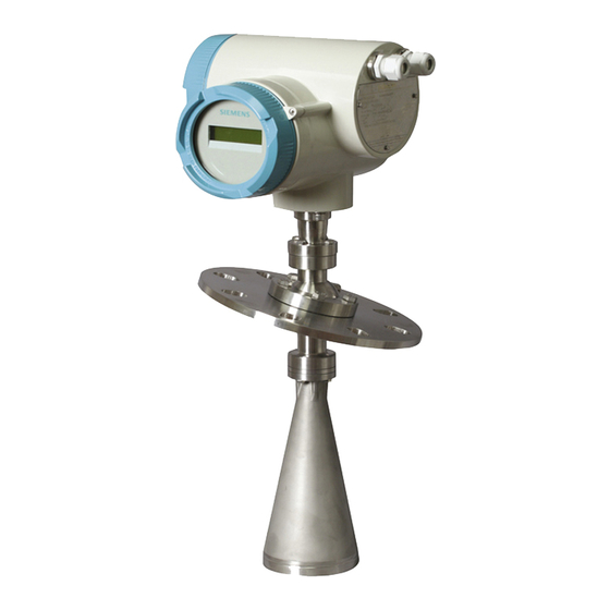
The high frequency signal creates a narrow emission cone, which makes the LR 460 quite insensitive to vessel interferences. SITRANS LR 460 is available with an optional air purge connection for cleaning the interior of the antenna. Programming SITRANS LR 460 carries out its level measurement function according to the set of built-in parameter tables. -
Page 14: Specifications
Specifications Siemens Milltronics makes every attempt to ensure the accuracy of these Note: specifications, but reserves the right to change them at any time. SITRANS LR 460 Power Power Supply ± • 100 to 230 V AC, 15%, 50/60 Hz, 6 W •... -
Page 15: Interface
16 characters each, configurable for the following displays: level, amplitude, digital output, temperature, validity, signal-to-noise ratio, output current, distance HART® is a registered trademark of HART Communication Foundation. 7ML19985JM01 SITRANS LR 460 – INSTRUCTION MANUAL Page 7... -
Page 16: Programmer (Infrared Keypad)
Programmer (infrared keypad) Siemens Milltronics infrared IS (Intrinsically Safe) handheld programmer for hazardous and all other locations (battery is non-replaceable) • approval: ATEX II 1 G EEx ia IIC T4, certificate SIRA 01ATEX2147 CSA and FM Class I, Div. 1, Gr. A, B, C, D T6 @ max. -
Page 17: Environmental
• Max. Line Length • Protocol HART, Version 5.1 Use only approved, suitable sized hubs for watertight applications. Process temperature varies with ambient temperature. See Process/Ambient de-rating curves in Appendix III. 7ML19985JM01 SITRANS LR 460 – INSTRUCTION MANUAL Page 9... -
Page 18: Approvals
FM/CSA Class II, Div. 1, Groups E,F and G, Class III ATEX II 1 D; 1/2 D, 2D T85 deg C • General CSAus/c, FM, CE • Radio FCC, Industry Canada, European Radio (R&TTE) Page 10 SITRANS LR 460 – INSTRUCTION MANUAL 7ML19985JM01... -
Page 19: Dimensions
4" horn (3.84") Consult factory when using horn extension in applications subject to shock and vibration. Universal flange mates with EN 1092-1 / ASME B16.5 / JIS B2238 bolt hole pattern. 7ML19985JM01 SITRANS LR 460 – INSTRUCTION MANUAL Page 11... -
Page 20: Installation
Installation WARNINGS: • SITRANS LR 460 is to be used only in the manner outlined in this manual, otherwise protection provided by the equipment may be impaired. • Installation shall only be performed by qualified personnel and in accordance with local governing regulations. -
Page 21: Key Considerations
Easy Aimer Installation (See on page 15.) 3" horn • To compensate for vessels with 11° Polarization obstructions, see also Reference Point on page 14. 7ML19985JM01 SITRANS LR 460 – INSTRUCTION MANUAL Page 13... -
Page 22: Installation In Vessel With Obstructions
To get the best signal, rotate the device till the Polarization Reference Point either faces towards the obstruction, or faces away from the obstruction (at 180 degrees). the device can be rotated through 360 Note: degrees without damage to the unit. Polarization Reference Point Page 14 SITRANS LR 460 – INSTRUCTION MANUAL 7ML19985JM01... -
Page 23: Easy Aimer Installation
Easy Aimer loosen the Easy Aimer ball locking bolts and gently reposition the enclosure. Direct SITRANS LR 460 so the horn antenna is pointed at an angle perpendicular to the material surface, if possible. (As a guide, aim the beam at a point approximately 2/3 of the way across the tank diameter.) -
Page 24: Air Purging System
• Some dust particles are highly abrasive and can be drawn into the inside of the horn during purge cleaning, damaging the internal PTFE emitter of the antenna. A replacement kit is available from your local Siemens Milltronics representative. • It is the customer’s responsibility to ensure that any vacuum or pressure in the measured vessel is maintained, considering the hole that passes through the process connection and SITRANS LR 460 antenna system. -
Page 25: Universal Slotted Flange (For Use With Air Purging Option Only)
100 mm (229 mm) (9.65 mm) (191 mm) (175 mm) (9.5 mm) 6" or 11.22" 0.38" 9.53" 9.45" 0.45" 150 mm (285 mm) (9.65 mm) (242 mm) (240 mm) (11.5 mm) 7ML19985JM01 SITRANS LR 460 – INSTRUCTION MANUAL Page 17... -
Page 26: Optional Dust Cap
Hand tighten the adjustable clamp supplied to secure the cap. Use a screwdriver or nut driver to tighten the clamp screw until the clamp provides an air-tight seal. It is critical to ensure no moisture can be trapped inside. Note: Page 18 SITRANS LR 460 – INSTRUCTION MANUAL 7ML19985JM01... -
Page 27: Wiring
Loosen the cable gland and push the power cable through until it reaches the terminal strip. cover lock cable gland power metal bracket cable terminal strip HART wiring PROFIBUS wiring (Go to on page 20 or on page 21 for next steps.) 7ML19985JM01 SITRANS LR 460 – INSTRUCTION MANUAL Page 19... -
Page 28: Hart Wiring
Connect the earth conductor of the power supply to the earth terminal on the metal bracket inside the enclosure. Adjust the cable length so that the earth conductor would be last to disconnect if cable is pulled. Page 20 SITRANS LR 460 – INSTRUCTION MANUAL 7ML19985JM01... -
Page 29: Profibus Wiring
Note: Power Demands To determine how many devices can be connected to a bus line, calculate the combined maximum current consumption of all the connected devices: 10.5 mA for SITRANS LR 460. Allow a current reserve for safety. Bus Termination PROFIBUS PA MUST be terminated at both extreme ends of the cable for it to work properly. -
Page 30: Connecting Profibus Pa
Connect the external earth terminal located cable glands between the cable glands to a ground connection at your vessel. Use a cable with a cross-section of 2.5 mm or greater. earth (ground) terminal Page 22 SITRANS LR 460 – INSTRUCTION MANUAL 7ML19985JM01... -
Page 31: Hazardous Area Installations
Essential Health and Safety Requirements are assured by compliance with IEC 61241-0: 2004 and IEC 61241-1: 2004. The equipment may be used with dust and fibers with apparatus temperature class T (see table below). 7ML19985JM01 SITRANS LR 460 – INSTRUCTION MANUAL Page 23... - Page 32 For applications that require the purge feature, the user shall implement a means to ensure that combustible dust from the hazardous area cannot enter the purge supply in such a way as to compromise the area classification. Page 24 SITRANS LR 460 – INSTRUCTION MANUAL 7ML19985JM01...
- Page 33 Notes 7ML19985JM01 SITRANS LR 460 – INSTRUCTION MANUAL Page 25...
-
Page 34: Quick Start
Quick Start SITRANS LR 460 only supports SIMATIC PDM version 6.0 with SP2. Note: To set up SITRANS LR 460 for a simple application requires only the following settings: • select application type (silo construction) • select operation mode: level, distance or space •... -
Page 35: Programming Sitrans Lr 460
Right ARROW parameter value to accept it. The LCD displays the new value and the PROGRAM icon disappears. • Press Mode to return to RUN mode. 7ML19985JM01 SITRANS LR 460 – INSTRUCTION MANUAL Page 27... -
Page 36: Quick Start Wizard Via The Handheld Programmer
Distance to material surface referenced from Low Calibration LEVEL Point (process empty level). Distance to High Calibration Point (process full level) SPACE Options referenced from material surface. Distance to material surface referenced from Sensor DISTANCE Reference Point. Page 28 SITRANS LR 460 – INSTRUCTION MANUAL 7ML19985JM01... - Page 37 In order to save the Quick Start settings it is necessary to enable Apply Changes. YES, NO Options Select YES. SITRANS LR 460 is now ready to operate and returns to RUN mode. 7ML19985JM01 SITRANS LR 460 – INSTRUCTION MANUAL...
-
Page 38: Quick Start Wizard Via Simatic Pdm
You will need the DD for SIMATIC PDM version 6.0 with SP2. You can locate the DD in Device Catalog, under Sensors/Level/Echo/Siemens Milltronics/SITRANS LR 460. If you do not see SITRANS LR 460 under Siemens Milltronics, you can download the DD from the product page of our website at: https://pia.khe.siemens.com/index.asp?Nr=14655, under Downloads. -
Page 39: Quick Start Wizard Steps
Open the menu Device – Quick Start, and follow steps 1 to 4. Quick Start Step 1 – Identification Click NEXT to accept default values. (Description, Message, and Last config fields can be left blank.) 7ML19985JM01 SITRANS LR 460 – INSTRUCTION MANUAL Page 31... - Page 40 Set Sensor Units, enter values for Low and High Calibration points, and select a Response Rate just faster than the maximum fill/empty rate. Click NEXT. Operation types For an illustration see on page 29. Page 32 SITRANS LR 460 – INSTRUCTION MANUAL 7ML19985JM01...
- Page 41 Step 4 – Summary Check parameter settings, and click BACK to return and revise values, or TRANSFER to transfer values to the device. The message Quick Start Finished appears. Click OK. 7ML19985JM01 SITRANS LR 460 – INSTRUCTION MANUAL Page 33...
-
Page 42: Level Application Example
Material level referenced from Low Calibration point. Units High Calibration Point Process full level. Low Calibration Point 15.5 Process empty level. Rate SLOW Response rate = 0.1 m/minute. Apply Changes Save new settings. Page 34 SITRANS LR 460 – INSTRUCTION MANUAL 7ML19985JM01... -
Page 43: Auto False Echo Suppression
Auto False Echo Suppression If SITRANS LR 460 displays a false high level, or the reading is fluctuating between the correct level and a false high level, you can use the Auto False Echo Suppression TVT (Auto False Echo Suppression) parameters to prevent false echo detection. -
Page 44: Operating Sitrans Lr 460 Via Simatic Pdm
• For a complete list of parameters with instructions, see starting on page 43. SIMATIC PDM is a software package used to commission and maintain SITRANS LR 460 and other process devices. Please consult the operating instructions or online help for details on using SIMATIC PDM. -
Page 45: Echo Profile Saving And Viewing
Double click each axis and record the Xscale and Data Scale values, so that you Note: can restore the default view by resetting to these values. Open the menu View – Trend to see the level trend over tme. trend line 7ML19985JM01 SITRANS LR 460 – INSTRUCTION MANUAL Page 37... -
Page 46: Manual Tvt Shaper
Change the position of the X cursor on the TVT curve using the Index+ and Index– buttons: raise and lower the curve using Value+ and Value–. • Alternatively, enter values directly into the dialog boxes for each breakpoint. Page 38 SITRANS LR 460 – INSTRUCTION MANUAL 7ML19985JM01... -
Page 47: Accessing Functions In Pdm
Pull-down menus via SIMATIC PDM For a complete list see on page 43. pull-down menus Online Display The online display allows you to compare outputs in real time. Open the menu View – Display. 7ML19985JM01 SITRANS LR 460 – INSTRUCTION MANUAL Page 39... -
Page 48: Changing Parameter Settings Via Simatic Pdm
You will need the DD for SIMATIC PDM version 6.0 with SP2. You can locate the DD in Device Catalog, under Sensors/Level/Echo/Siemens Milltronics/SITRANS LR 460. If you do not see SITRANS LR 460 under Siemens Milltronics, you can download the DD from the product page of our website at: https://pia.khe.siemens.com/index.asp?Nr=14655, under Downloads. -
Page 49: Calibrating Lr 460 Via Pdm
Use this parameter to learn a new TVT curve, to avoid false echoes caused by Auto False-Echo Suppression obstructions. See on page 71 for a more detailed TVT (Auto False Echo Suppression) setup explanation and on page 56 for instructions. 7ML19985JM01 SITRANS LR 460 – INSTRUCTION MANUAL Page 41... -
Page 50: D/A (Digital/Analog) Trim
2. To enable simulation select Fixed or Ramp. If you select Ramp, enter the step length and number of steps. 3. Enter the simulated value and click Transfer. 4. After simulation is complete, disable simulation. Page 42 SITRANS LR 460 – INSTRUCTION MANUAL 7ML19985JM01... -
Page 51: Parameter Reference
Echo Profile Maintenance Show Echo Profile Selftest Status Reset Read Analog Value Configuration Flag Reset Clear Faults D/A Trim Peak Values Write Locking Wear Simulate AO HART Communication Simulation Sensor Calibration 7ML19985JM01 SITRANS LR 460 – INSTRUCTION MANUAL Page 43... -
Page 52: Quick Start Wizard
Options referenced from material surface. Distance to material surface referenced from Sensor DISTANCE Reference Point. Operation types sensor reference point high (flange face) calibration point distance space level low calibration point Page 44 SITRANS LR 460 – INSTRUCTION MANUAL 7ML19985JM01... -
Page 53: Units
There is no specific recommended use. Message Text that is associated with the Field Device. This text can be used by the user in any way. There is no specific recommended use.. 7ML19985JM01 SITRANS LR 460 – INSTRUCTION MANUAL Page 45... -
Page 54: Configuration
START Values Reset PROFIBUS address to 126 ADDRESS (PROFIBUS version only). NONE No reset performed. Via PDM, open menu Device – Reset, and click on Factory Reset. Page 46 SITRANS LR 460 – INSTRUCTION MANUAL 7ML19985JM01... -
Page 55: Device
Uniquely identifies the Field Device. This variable cannot be modified by the Host. Order No. The order number for this device. Date of birth Date of manufacture. 2.2.1. Software Revision Corresponds to the software or firmware that is embedded in the Field Device. 7ML19985JM01 SITRANS LR 460 – INSTRUCTION MANUAL Page 47... -
Page 56: Statistics
Open the menu Device – Write Locking, and select On or Off. 2.2.5. Language Selects the language to be used on the LCD. English German Options French Spanish 2.3. Statistics To view Statistics via PDM, open the menu View – Wear. Page 48 SITRANS LR 460 – INSTRUCTION MANUAL 7ML19985JM01... -
Page 57: Input
Slower settings provide higher accuracy and a smoother output signal: faster settings allow for more level fluctuation. 3.5. 1 . 1 . LOE (Loss of Echo) Timer For instructions on usage see . For technical details LOE Timer 7ML19985JM01 SITRANS LR 460 – INSTRUCTION MANUAL Page 49... -
Page 58: Sensor Calibration
DRY CAL Dry calibration Options WET CAL Wet calibration (not recommended for SITRANS LR 460) 3.3.3. Low Calibration Pt. (default 30.000 m) Distance from Sensor Reference to Low Calibration Point (corresponding to Low Level Point). Unit is defined in Sensor units. - Page 59 Compensates, for example if the sensor head is changed. 3.3.A. Temperature Units Selects the engineering unit to be displayed with the value representing temperature. °C, °F, °R, °K Options default: °C 7ML19985JM01 SITRANS LR 460 – INSTRUCTION MANUAL Page 51...
-
Page 60: Measuring Limits
Echo must persist, before the device goes into Fail-safe mode. See Fail- safe Mode for more details. Range: 0.00 to 720 (minutes) Values Default: 10.000 In PDM, open View menu, scroll down to Peak Values, and click Sensor tab. Page 52 SITRANS LR 460 – INSTRUCTION MANUAL 7ML19985JM01... - Page 61 Default: 10 Related LOE Timer Parameters Use this feature when an incorrect material level is reported. 3.5.2.3. Echo Marker The point on the selected echo from which the measured value is taken. 7ML19985JM01 SITRANS LR 460 – INSTRUCTION MANUAL Page 53...
- Page 62 When the value is 0, the window is automatically calculated after each measurement. • For slower Measurement Response values, the window is narrow. • For faster Measurement Response values, the window becomes progressively wider. Page 54 SITRANS LR 460 – INSTRUCTION MANUAL 7ML19985JM01...
- Page 63 Note: Maximum distance from the reference point, within which an echo should be considered valid. Range: 0 to 100 m max. Values Default: The value of Low Calibration Point plus 20%. 7ML19985JM01 SITRANS LR 460 – INSTRUCTION MANUAL Page 55...
- Page 64 False Echo Suppression must be re-enabled, to relearn the TVT curve SITRANS LR 460 first learns the echo profile. Then the learned profile, or part of it, is used to screen out false echoes. (See Auto False-Echo Suppression on page 71 for a more detailed explanation.)
- Page 65 Display before Auto False Echo Suppression default material surface false echo Echo Marker Example after Auto False Echo Suppression material surface learned TVT curve false echo 7ML19985JM01 SITRANS LR 460 – INSTRUCTION MANUAL Page 57...
- Page 66 Access the submenu for the breakpoint number in question and enter values for all desired breakpoints. 3.5.7.1. Shaper A (1 - 9). 3.5.7.2. Shaper B (10 - 18) 3.5.7.3. Shaper C (19 - 27) Page 58 SITRANS LR 460 – INSTRUCTION MANUAL 7ML19985JM01...
- Page 67 / min. Values Default: 10.000 Response Rate Altered by Related Units (Level) High Level Point Enter a value slightly greater than the vessel’s maximum emptying rate, in Sensor Units per minute. 7ML19985JM01 SITRANS LR 460 – INSTRUCTION MANUAL Page 59...
-
Page 68: Echo Information
Static Revision No. The revision level of the static data associated with Analog Input Function Block 1. The Static Revision No. is updated whenever a standard profile configuration parameter is changed. Page 60 SITRANS LR 460 – INSTRUCTION MANUAL 7ML19985JM01... - Page 69 Identifies the active Control Recipe Unit Procedure or the related Unit (for example, reactor, centrifuge, drier). 4.1.5.3. Batch operation Identifies the active Control Recipe Operation. 4.1.5.4. Batch Phase Identifies the active Control Recipe Phase. 7ML19985JM01 SITRANS LR 460 – INSTRUCTION MANUAL Page 61...
- Page 70 The setting for the lower warning limit in engineering units. 4.1.8.3. Upper Limit Warning The setting for the upper warning limit in engineering units. 4.1.8.4. Upper Limit Alarm The setting for the upper alarm limit in engineering units Page 62 SITRANS LR 460 – INSTRUCTION MANUAL 7ML19985JM01...
- Page 71 Out unit text If the code list does not contain a desired unit for the OUT parameter, (see General Requirement) you can write the specific text in this parameter. 7ML19985JM01 SITRANS LR 460 – INSTRUCTION MANUAL Page 63...
-
Page 72: Aifb2
A user-defined mA value which can be used either for simulation, or to do a digital/ analog trim. Range: 3.8 to 20.5 mA. Values To set the mA Output via PDM, open the menu Device – Simulate AO and select an option. Page 64 SITRANS LR 460 – INSTRUCTION MANUAL 7ML19985JM01... - Page 73 4.3.8. 4 mA Trim d. Enter the recorded value in 4.3. 1 . Function e. Restore to its previous setting. f. Confirm that the mA output is as expected. 7ML19985JM01 SITRANS LR 460 – INSTRUCTION MANUAL Page 65...
-
Page 74: Relay Configuration
HI ALM Options ANY ALM FAIL-SAFE 4.4.3. NC/NO Normally Open Handheld programmer Normally Closed options 4.4.4. State OFF * Relay de-energized Handheld programmer Relay energized options Certificates and Approvals Device Certification Page 66 SITRANS LR 460 – INSTRUCTION MANUAL 7ML19985JM01... -
Page 75: Remaining Device Lifetime
A factory default can be reset by the user. 6.2.1. Total Sensor Operating Time 6.2.2. Remaining Sensor Lifetime 6.2.3. Maintenance Required Limit 6.2.4. Maintenance Demanded Limit 6.2.5. Maintenance Alert Activation 7ML19985JM01 SITRANS LR 460 – INSTRUCTION MANUAL Page 67... -
Page 76: Service Interval
A factory default can be reset by the user. 6.4.1. Time Elapsed Since Last Calibration 6.4.2. Maintenance Required Limit 6.4.3. Maintenance Demanded Limit 6.4.4. Maintenance Alert Activation 6.4.5. Total Calibration Interval 6.4.6. Maintenance Status 6.4.7. Acknowledge Status 6.4.8. Acknowledge Page 68 SITRANS LR 460 – INSTRUCTION MANUAL 7ML19985JM01... -
Page 77: Appendix A: Technical Reference
Appendix A: Technical Reference Principles of Operation SITRANS LR 460 is a long range FMCW (Frequency Modulated Continuous Wave) radar transmitter. Radar level measurement uses the time of flight principle to determine distance to a material surface. FMCW radar transmits a continuous wave. The frequency of the wave is constantly increasing: this is known as the sweep. -
Page 78: Echo Processing
Each peak gets a rating based on its strength, area, height above the TVT, and other Echo Algorithm parameters. The true echo is selected based on the setting for on page 53. Page A-70 SITRANS LR 460 – INSTRUCTION MANUAL 7ML19985JM01... -
Page 79: False Echoes
The TVT adjustment parameters allow you to manipulate the TVT (Time Varying Threshold), so that SITRANS LR 460 will ignore false echoes. The default TVT hovers above the echo profile, and effectively screens out small false echoes. -
Page 80: Near Range (Blanking)
Fail-safe mode defines the reaction of the device if a Fail-safe condition is detected, so that the process will be put into a safe state in the event of a fault or failure. The particular application determines whether a high or low level is safe. Page A-72 SITRANS LR 460 – INSTRUCTION MANUAL 7ML19985JM01... - Page 81 User-defined default value (Fail-safe value) used as output value. • Store last valid output value. • Calculated output value is incorrect. Fail-safe value The user-defined Fail-safe value allows you to enter the safest output value for your application. 7ML19985JM01 SITRANS LR 460 – INSTRUCTION MANUAL Page A-73...
-
Page 82: Maximum Process Temperature Chart
• It does not take into consideration temperature heating from direct sunshine exposure. process temperature Where the chart does not apply, please use your own judgement regarding the use of SITRANS LR 460. Page A-74 SITRANS LR 460 – INSTRUCTION MANUAL 7ML19985JM01... -
Page 83: Appendix B: Troubleshooting
Check the HART (or PROFIBUS) address and make sure all devices are at unique HART (or PROFIBUS) addresses. If you continue to experience problems, go to our website at: www.siemens.com/processautomation, and check the FAQs for SITRANS LR 460, or contact your Siemens Milltronics representative. Troubleshooting LR 460... - Page 84 You are unable Remote operation enable enabled. See to modify a (REMLOCK) on page 46. Also make sure parameter via Write that Write Locking is Off. See remote Locking on page 48. communications Page B-76 SITRANS LR 460 – INSTRUCTION MANUAL 7ML19985JM01...
- Page 85 PLC, instead of are communicating. (regardless of leaving all scaling to be actual material performed in the LR 460. level). • The PLC may not be communicating with the LR 460. 7ML19985JM01 SITRANS LR 460 – INSTRUCTION MANUAL Page B-77...
-
Page 86: General Fault Codes/Profibus Pa Extended Diagnostics
Replacement is limit according to the value recommended. set in Maintenance Required Limit. Sensor is nearing its lifetime Replacement is limit according to the value recommended. set in Maintenance Demanded Limit. Page B-78 SITRANS LR 460 – INSTRUCTION MANUAL 7ML19985JM01... - Page 87 Check configuration for Upper and lower input values AIFB2. Ensure that Upper (Process Value Scale) for Value and Lower Value S:15 AIFB2 are the same. (Process Value Scale) are not the same. 7ML19985JM01 SITRANS LR 460 – INSTRUCTION MANUAL Page B-79...
- Page 88 Selector do not correspond. the device needs to be re- parameterized by the PLC. Factory calibration for the Repair required: contact your internal temperature sensor local Siemens S:33 has been lost. representative. Page B-80 SITRANS LR 460 – INSTRUCTION MANUAL 7ML19985JM01...
- Page 89 Siemens S:38 distance measurement. representative. The mA calibration was not Perform a current trim to retrieved from EEPROM and calibrate the 4 mA and 20 mA S:51 is corrupt. points. 7ML19985JM01 SITRANS LR 460 – INSTRUCTION MANUAL Page B-81...
-
Page 90: Appendix C: Maintenance
Appendix C: Maintenance SITRANS LR 460 requires no maintenance or cleaning under normal operating conditions. Under severe operating conditions, the antenna may require periodic cleaning. If cleaning becomes necessary: • We recommend using high pressure air to clean the antenna. -
Page 91: Appendix D: Local Operation Interface
Appendix D: Local Operation Interface The LCD Display SITRANS LR 460 continues to monitor In and Out values even when the device is Note: in PROGRAM mode. RUN mode (startup display) Normal operation LOE condition 98.82 98.82 3.800 mA S: 0 1 –... -
Page 92: The Handheld Programmer
To activate PROGRAM mode, point the handheld programmer at the display (from a maximum distance of 600 mm [2 ft.]), and press the Mode key display number max. 600 mm keys (2 ft) handheld programmer function keys Page D-84 SITRANS LR 460 (HART) – INSTRUCTION MANUAL 7ML19985JM01... -
Page 93: Hand-Held Programmer: Key Functions In Navigation Mode
Press Right ARROW , then CLEAR , then Right ARROW The value returns to the default factory setting. For example, press 3 to move to the third item in the current menu. 7ML19985JM01 SITRANS LR 460 (HART) – INSTRUCTION MANUAL Page D-85... -
Page 94: Appendix E: Hart Communications
SITRANS LR 460 cannot be set up using a generic DD. The configuration software needs the HART Device Description for SITRANS LR 460. You can download the HART DD for SITRANS LR 460 from the product page of our website. Go to: https://pia.khe.siemens.com/index.asp?Nr=14655 and click on Downloads. -
Page 95: Hart Version
HART Version SITRANS LR 460 conforms to HART rev. 5.1. Burst Mode SITRANS LR 460 does not support Burst Mode. HART Communication Parameter Warning: Incorrect use of this parameter can cause all communication to be lost. To set the number of preamble requests open the menu Device – HART Communication. -
Page 96: Appendix F: Hart Information Structure
Appendix F: HART Information Structure SITRANS LR 460 detects a material level via the sensor, and then processes that information to provide a measured value. The measured value is conveyed as a digital signal. The LR 460 device design enables it to provide outputs to two different channels: •... -
Page 97: Description Of The Blocks
Variable. This can only be viewed via the HART digital channel. Description of the blocks For a detailed description of how the Level Transducer Block and Analog Input Function Description of the blocks Blocks process information, see on page 98. 7ML19985JM01 SITRANS LR 460 (HART) – INSTRUCTION MANUAL Page F-89... -
Page 98: Appendix G: Remote Operation Via Profibus Pa
Appendix H: Communication via PROFIBUS PA • See on page 93 for more details. • The full range of SITRANS LR 460 functions is available only over a PROFIBUS PA network. PROFIBUS PA is an open industrial protocol. Full details about PROFIBUS PA can be obtained from PROFIBUS International at www.profibus.com. -
Page 99: Configuration
GSD file. The GSD file The GSD file SIEM8132.gsd is available from the SITRANS LR 460 product page on our web site. Go to https://pia.khe.siemens.com/index.asp?Nr=14655 and click Downloads. Download the DeviceInstall, and run it from your computer. This will install the GSD file into your system (as long as you are using SIMATIC software). -
Page 100: Configuring Profibus Pa With An S7-300/ 400 Plc
Configuring PROFIBUS PA with an S7-300/ 400 PLC If SITRANS LR 460 is not listed in the STEP 7 device catalog, you can download the DeviceInstall file from the Siemens Milltronics Web site and run it from your computer. Go to https://pia.khe.siemens.com/index.asp?Nr=14655 and click Downloads. -
Page 101: Appendix H: Communication Via Profibus Pa
Appendix H: Communication via PROFIBUS PA SITRANS LR 460 is a Class B, Profile Version 3.01, PA device. It supports Class 1 Master for cyclic and acyclic data exchange, and Class 2 for acyclic services. The full range of SITRANS LR 460 functions is available only over a PROFIBUS PA network. -
Page 102: Status Byte
This could happen when a firmware download has been done, but a system reset has not been done. This could also happen if the function blocks are not configured properly using PDM or acyclic services. Page H-94 SITRANS LR 460 (PROFIBUS PA) – INSTRUCTION MANUAL 7ML19985JM01... -
Page 103: Diagnostics
0x80000000 Self calibration failed R indicates the message remains active as long as the reason for the message exists. A indicates the message will automatically reset after 10 seconds 7ML19985JM01 SITRANS LR 460 (PROFIBUS PA) – INSTRUCTION MANUAL Page H-95... -
Page 104: Acyclic Extended Diagnostics (General Fault Codes)
78. Acyclic Data Transmission SITRANS LR 460 supports up to four simultaneous connections by a Class 2 Master (C2 connection). It supports one connection by a Class 1 Master (C1 connection). You can download a Data Map containing a list of all acyclic data, including slot and index addresses, format, range of values, start value, and attributes. -
Page 105: Appendix J: Profibus Pa Profile Structure
TB, and apply any required quality checks, scaling, and Fail-safe operation selections. The output of an Analog Input Function Block supplies the measured value and associated status information to PROFIBUS PA, via cyclic data transfer. 7ML19985JM01 SITRANS LR 460 (PROFIBUS PA) – INSTRUCTION MANUAL Page J-97... -
Page 106: Description Of The Blocks
A Linearization module is required by the PROFIBUS PA specifications. The Linearization block is turned off in SITRANS LR 460. Page J-98 SITRANS LR 460 (PROFIBUS PA) – INSTRUCTION MANUAL... - Page 107 The Level Transducer Block (LTB) provides three possible outputs • Primary Value (PV)/Level • Secondary Value 1 (SV1)/Level (plus level offset, if any) • Secondary Value 2 (SV2)/Distance (in Sensor units) 7ML19985JM01 SITRANS LR 460 (PROFIBUS PA) – INSTRUCTION MANUAL Page J-99...
-
Page 108: Analog Input Function Blocks 1 And 2
The output from the Level Transducer Block can be called the Primary Value (or Secondary Value). When it becomes the input to the AIFB, it is called the Process Variable. Page J-100 SITRANS LR 460 (PROFIBUS PA) – INSTRUCTION MANUAL 7ML19985JM01... - Page 109 The scaling output is applied. For example: AIFB Out (or AIFB Out) straight to LCD (same values displayed on LCD as PLC) Output range: 7ML19985JM01 SITRANS LR 460 (PROFIBUS PA) – INSTRUCTION MANUAL Page J-101...
- Page 110 A hysteresis parameter prevents toggling in the Status field of the OUT value.) The OUT VALUE parameter is the value for the cyclic data transfer. Page J-102 SITRANS LR 460 (PROFIBUS PA) – INSTRUCTION MANUAL 7ML19985JM01...
-
Page 111: Appendix K: Software Revision History
Appendix K: Software Revision History The software revision number of the device is shown on the sticker on the Note: product. Software DD Rev. Date Changes Rev. 1.02.00-00 1.02.01-00 12/01/2006 • Initial release. • 7ML19985JM01 SITRANS LR 460 – INSTRUCTION MANUAL Page K-103... - Page 112 Notes Page K-104 SITRANS LR 460 – INSTRUCTION MANUAL 7ML19985JM01...
-
Page 113: Glossary
1. Many conductive liquids/electrolytes exhibit dielectric properties; the relative dielectric constant of water is 80. 7ML19985JM01 SITRANS LR 460 – INSTRUCTION MANUAL Page 105... - Page 114 Page 106 SITRANS LR 460 – INSTRUCTION MANUAL 7ML19985JM01...
- Page 115 TVT (time varying threshold): a time-varying curve that determines the threshold level above which echoes are determined to be valid. waveguide antenna: a hollow, metallic tube that transmits a microwave signal to the product target. 7ML19985JM01 SITRANS LR 460 – INSTRUCTION MANUAL Page 107...
- Page 116 Notes Page 108 SITRANS LR 460 – INSTRUCTION MANUAL 7ML19985JM01...
-
Page 117: Index
23 Device Description (DD) requirements 12 how to update 40 device description (DD) Level application example 34 PROFIBUS PA 90 LOE timer diagnostics 95 explanation 72 dimensions 11 maintenance 7ML19985JM01 SITRANS LR 460 – INSTRUCTION MANUAL Page 109... - Page 118 PROFIBUS PA 21 Quick Start Wizard via handheld programmer 28 via SIMATIC PDM 30 Range Far Range (range extension) 55 Near Range (blanking) 55 reliable echo indicator 83 repair cautions 82 Page 110 SITRANS LR 460 – INSTRUCTION MANUAL 7ML19985JM01...
-
Page 119: Lcd Menu Structure
LCD menu structure SITRANS LR 460 (HART/PROFIBUS PA) – INSTRUCTION MANUAL Page 111 SITRANS LR 460 (HART/PROFIBUS PA) – INSTRUCTION MANUAL 7ML19985JM01... - Page 120 113. ECHO QUAL 1. ECHO CON L 2. STRENGTH MAINT SET 6. MAINT SET MAINT SET on page 114 Page 112 SITRANS LR 460 (HART/PROFIBUS PA) – INSTRUCTION MANUAL SITRANS LR 460 (HARAT/PROFIBUS PA) – INSTRUCTION MANUAL 7ML19985JM01...
- Page 121 3. MAN VALUE 4. MIN LIM 5. MAX LIM 6. FS MODE 7. FS VALUE 8. 4 MA TRIM 9. 20 MA TRIM RLY CONFIG 1. AIFB 2. FUNCTION 3. NC/NO 4. STATE 7ML19985JM01 SITRANS LR 460 – INSTRUCTION MANUAL Page 113...
- Page 122 5. INTERVAL 6. MAINT STAT 7. ACK STATUS 8. ACK 1. LAST CAL 2. REQ LIMIT 3. DEM LIMIT 4. ACTIVATION 5. INTERVAL 6. MAINT STAT 7. ACK STATUS 8. ACK Page 114 SITRANS LR 460 – INSTRUCTION MANUAL 7ML19985JM01...
- Page 123 Siemens Milltronics Process Instruments Inc. Siemens Milltronics Process Instruments Inc. 2006 1954Technology Drive, P .O. Box 4225 Subject to change without prior notice Peterborough, ON, Canada K9J 7B1 Tel: (705) 745-2431 Fax: (705) 741-0466 *7ml19985JM01* Rev. 1.0 Email: techpubs.smpi@siemens.com...
Need help?
Do you have a question about the sitrans lr 460 and is the answer not in the manual?
Questions and answers