Siemens Sitrans LR 460 Instruction Manual
Hide thumbs
Also See for Sitrans LR 460:
- Quick start manual (197 pages) ,
- Operating instructions manual (187 pages) ,
- Instruction manual (123 pages)
Table of Contents
Advertisement
Quick Links
Advertisement
Table of Contents

Subscribe to Our Youtube Channel
Related Manuals for Siemens Sitrans LR 460


Summary of Contents for Siemens Sitrans LR 460
- Page 1 Instruction Manual February 2006 Draft Manual 02/13/2006 sitrans LR 460...
- Page 2 The user is responsible for all changes and repairs made to the device by the user or the user’s agent. • All new components are to be provided by Siemens Milltronics Process Instruments Inc. • Restrict repair to faulty components only.
-
Page 3: Table Of Contents
Application Examples ........................3 Abbreviations and Identifications .....................3 Programming ............................4 Approvals and Certificates ......................4 Part I: SITRANS LR 460 (all versions) ........1 SITRANS LR 460 ........................2 System Implementation .........................3 Typical PLC/mA configuration with HART................3 Typical PLC/mA configuration with PROFIBUS PA............. 3 ................................3... - Page 4 Hazardous area installations ......................22 Product Nameplate ........................22 Instructions specific to hazardous area installations ............22 EU Equivalency .......................... 23 Part II: SITRANS LR 460 4-20 mA version ......25 4-20 mA Start Up .......................26 Startup Display (RUN mode) ................26 Programming SITRANS LR 460....................27 The handheld programmer .......................27...
- Page 5 Maintenance settings (accessible via PDM only) ..............41 Supported HART Commands: ......................42 Universal and Common Practice Commands ...............43 Device Specific Commands ......................43 Part III: SITRANS LR 460 PROFIBUS PA version....45 Remote operation via PROFIBUS PA ................46 SIMATIC PDM ............................46 Device Description ..........................46 Configuration ............................47...
- Page 6 Measuring Limits........................64 Detailed Setup ........................... 65 Output ..............................72 AIFB1............................72 AIFB2............................74 Device Certification ........................75 Maintenance settings ........................75 Remaining Device Lifetime ..................... 75 Remaining Sensor Lifetime..................... 75 Service Interval.......................... 75 Calibration Interval........................76 Condensed Status Setup ........................76 Condensed Status Mode ......................76 Appendix B: Technical Reference .................82 Principles of Operation ........................82 Measurement Response ........................82...
-
Page 7: Safety Notes
Safety marking symbols In manual: On product: Description Earth (ground) Terminal Protective Conductor Terminal Alternating Current Direct Current (Label on product: yellow background.) WARNING: refer to accompanying documents (manual) for details. 7ML19985JM01 SITRANS LR 460 – INSTRUCTION MANUAL Page 1... -
Page 8: The Manual
This manual applies to the SITRANS LR 460 only. This manual will help you set up your SITRANS LR 460 for optimum performance. SITRANS LR 460 is available in two versions (HART or PROFIBUS PA), and the manual is in three parts: Part I: information common to both versions •... -
Page 9: Application Examples
The application example used in this manual illustrates a typical installation using SITRANS LR 460. Because there is often a range of ways to approach an application, other configurations may also apply. If the example does not apply to your application, check the applicable parameter reference for the available options. -
Page 10: Programming
Process Variable. Programming SITRANS LR 460 carries out its level measurement function according to the set of built-in parameter tables. You can make parameter changes via the Siemens Milltronics handheld programmer, a PC running SIMATIC PDM or a HART handheld communicator. - Page 11 Part I: SITRANS LR 460 (all versions) 7ML19985JM01 SITRANS LR 460 – INSTRUCTION MANUAL Page I-1...
-
Page 12: Sitrans Lr 460
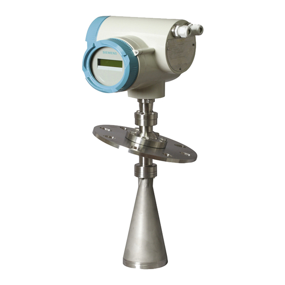
SITRANS LR 460 SITRANS LR 460 is a long-range FMCW radar level transmitter for level measurement of solids. It can be used in high pressure applications or applications requiring gas safety approvals. The Easy Aimer design makes it easy to set up the device even in conditions of extreme dust. -
Page 13: System Implementation
System Implementation SITRANS LR 460 supports HART communication protocol, and SIMATIC PDM software. Typical PLC/mA configuration with HART PLC with mA input card HART HART Communicator 275 PC/laptop with HART S ITR A N S LR 4 00 modem running PDM SITRANS LR 460 A 250 ohm loop resistor may be required, depending on PLC input resistance. - Page 14 Page I- 4 SITRANS LR 460 – INSTRUCTION MANUAL 7ML19985JM01...
-
Page 15: Specifications
Specifications Siemens Milltronics makes every attempt to ensure the accuracy of these Note: specifications, but reserves the right to change them at any time. SITRANS LR 460 Power Power Supply (HART) ± • 100 to 230 V AC, 15%, 50/60 Hz, 6 W (12VA) •... -
Page 16: Interface
Programmer (infrared keypad) Siemens Milltronics infrared IS (Intrinsically Safe) handheld programmer for hazardous and all other locations (battery is non-replaceable) • approval: ATEX II 1 G EEx ia IIC T4, certificate SIRA 01ATEX2147 CSA and FM Class I, Div. -
Page 17: Mechanical
Die-cast aluminum, painted (polyester powder-coated) • conduit 2 x M20 or 2 x ½” NPT (option) • ingress protection Type 4X/NEMA 4X, Type 6/NEMA 6, IP67 Use only approved, suitable sized hubs for watertight applications. 7ML19985JM01 SITRANS LR 460 – INSTRUCTION MANUAL PageI-7... -
Page 18: Environmental
• Software for PC/Laptop Windows 95/98/2000/XP or NT 4.0 SIMATIC® PDM See Process/Ambient de-rating curves in Appendix III. -20 °C (-4 °F) temperature rating available on SITRANS LR 460 with ATEX rating. Page I-8 SITRANS LR 460 – INSTRUCTION MANUAL 7ML19985JM01... -
Page 19: Approvals
• Hazardous areas FM/CSA Class II, Div. 1, Groups E,F and G, Class III ATEX II 1/2 D T6 • General CSAus/c, FM, CE • Radio FCC, Industry Canada, European Radio (R&TTE) 7ML19985JM01 SITRANS LR 460 – INSTRUCTION MANUAL PageI-9... -
Page 20: Sitrans Lr 460 Dimensions
100 mm (3.94") Consult factory when using horn extension in applications subject to shock and vibration. Universal flange mates with DIN 2527 / ANSI B16.5 / JIS B2238 bolt hole pattern. Page I-10 SITRANS LR 460 – INSTRUCTION MANUAL 7ML19985JM01... -
Page 21: Flange Dimensions
(9.65 mm) (242 mm) (240 mm) (11.5 mm) Universal Slotted Flange Diagram number of slotted bolt holes bolt hole circle max. diameter bolt hole circle min. diameter flange O.D. thickness section A-A 7ML19985JM01 SITRANS LR 460 – INSTRUCTION MANUAL PageI-11... - Page 22 Short bursts of high pressure periodically are more effective for purging than Note: continuous low pressure. purged process connection with factory-installed 1/2" NPT plug alignment markings SCFM: standard cubic feet/minute referenced to 14.7 psia, 68°F and 36% relative humidity (RH) Page I-12 SITRANS LR 460 – INSTRUCTION MANUAL 7ML19985JM01...
-
Page 23: Installation
Installation WARNINGS: • SITRANS LR 460 is to be used only in the manner outlined in this manual, otherwise protection provided by the equipment may be impaired. • Installation shall only be performed by qualified personnel and in accordance with local governing regulations. - Page 24 The concavity of the top can focus echoes into the the unit at the center. centre, giving false readings. Flat Parabolic or Conical l i c is acceptable is preferred location location Page 14 SITRANS LR 460 – INSTRUCTION MANUAL 7ML19985JM01...
-
Page 25: Beam Width
If the process nozzle diameter is greater than 6", the antenna does not need to project beyond the nozzle unless the emission cone touches the nozzle wall. SITRA NS LR 400 GRAPHIC TO BE UPDATED 10 mm 7ML19985JM01 SITRANS LR 460 – INSTRUCTION MANUAL Page 15... -
Page 26: Easy Aimer Installation
30° max. Easy Aimer Positioning Easy Aimer • Direct SITRANS LR 460 so the horn antenna is pointed at an angle to the filling level as shown. • Loosen the Easy Aimer ball locking bolts and position the LR 460. - Page 27 Notes 7ML19985JM01 SITRANS LR 460 – INSTRUCTION MANUAL Page 17...
- Page 28 Page 18 SITRANS LR 460 – INSTRUCTION MANUAL 7ML19985JM01...
-
Page 29: Wiring
AC and DC input circuits: min 14 AWG copper wire • Recommended torque on terminal clamping screws, 0.5 - 0.6 Nm Connecting SITRANS LR 460 If the device is rotated, return the orientation of the housing to its previous position with reference to the enclosure, to ensure similar performance. -
Page 30: Ac Version
Install in accordance with in the HART Application Guide (order number HCF_LIT-34), available from : http://www.hartcomm.org/technical/doclist.html. PROFIBUS PA User and Installation Guidelines Install in accordance with (order number 2.092), available from www.profibus.com. Page 20 SITRANS LR 460 – INSTRUCTION MANUAL 7ML19985JM01... - Page 31 Use a cable with a diameter of 2.5 mm greater. SIEMENS For error-free communication via the HART protocol, a load of at least 230 Ω must be earth (ground) available in the signal circuit.
-
Page 32: Hazardous Area Installations
Health and Safety Requirements are assured by compliance with EN 50281-1-1:1998; Dust Explosion Protection. The equipment may be used with dust and fibers with apparatus temperature class T. See table below. Page 22 SITRANS LR 460 – INSTRUCTION MANUAL 7ML19985JM01... -
Page 33: Eu Equivalency
• Permitted ambient temperature at the horn antenna (Category 1D): ≤ ≤ - 20 °C +200 °C • Permitted ambient temperature at the electronic enclosure (Category 2D): ≤ ≤ -20 °C +65 °C • Maximum permitted temperature within electronic enclosure (Category 1D): 85 °C Maximum surface Ambient temperature at the... - Page 34 Page 24 SITRANS LR 460 – INSTRUCTION MANUAL 7ML19985JM01...
- Page 35 Part II: SITRANS LR 460 4-20 mA version 7ML19985JM01 SITRANS LR 460 (4-20 mA) – INSTRUCTION MANUAL Page II-25...
-
Page 36: Ma Start Up
Use SIMATIC PDM to calibrate the four set points: High and Low Calibration Point, and High and Low Level Point. SITRANS LR 460 automatically starts up in RUN mode and detects the material level. The LCD displays the material level referenced from the Low Level Point (the output of Analog Input Function Block 1 or 2). -
Page 37: Programming Sitrans Lr 460
LCD menu structure number (see on page 37 for details). Programming via the handheld programmer on page 33 for more detail. When there is no further menu sub-level to access. 7ML19985JM01 SITRANS LR 460 (4-20 mA) – INSTRUCTION MANUAL Page II-27... -
Page 38: Program Mode Display
Pressing a number key enters parameter data. • In the case of read-only parameters, no change is permitted. PROGRAM Mode Display SITRANS LR 460 continues to monitor In and Out values even when the device is Note: in PROGRAM mode. 1 – Menu level 2 –... -
Page 39: Write Locking
Keep infrared devices such as laptops, cell phones, and PDAs, away from Note: SITRANS LR 460 to prevent inadvertent operation. Power up the instrument. SITRANS LR 460 starts in RUN mode, and the LCD displays the output of AIFB1 or AIFB2. Performing calibration via PDM... -
Page 40: Using Auto False Echo Suppression
SITRANS LR 460 is now ready to operate. Using Auto False Echo Suppression If SITRANS LR 460 displays a false high level, or the reading is fluctuating between the correct level and a false high level, you can use the Auto False Echo Suppression TVT (Auto False Echo Suppression) parameters to prevent false echo detection. -
Page 41: Level Application Example
Low Level Point Calibration Level = 0% Point = 5 m Offset any) Secondary Value 1 Far Range SITRANS LR 460 Dimensions For standard configuration reference point, see on page 7ML19985JM01 SITRANS LR 460 (4-20 mA) – INSTRUCTION MANUAL Page II-31... - Page 42 Page II-32 SITRANS LR 460 (4-20 mA) – INSTRUCTION MANUAL 7ML19985JM01...
-
Page 43: Local Operation
Local Operation Programming via the handheld programmer Although the complete range of parameters is only accessible via PDM , you can access and adjust many of the parameters via the Siemens Milltronics infrared handheld programmer. Appendix A: Parameter Descriptions •... -
Page 44: Using The Handheld Programmer
Detailed instructions on using the handheld programmer start on page 25, and on doing a Quick Setup start on page 27. The following pages give details on how to programme some of the more complex SITRANS LR 460 parameters via the handheld programmer. Security Local operation enable Local Operation can be enabled or disabled via PDM. -
Page 45: How To Do A Master Reset
Key in the number of the Fault Code to reset the status to normal operation. Manufacturer’s settings: AIFB Filter Time Constant = 10 s LTB values set for 0 - 20 m (Low and High Calibration points; Near Range and Far Range) 7ML19985JM01 SITRANS LR 460 – INSTRUCTION MANUAL Page 35... -
Page 46: Device Calibration
2.3. Sensor Calibration: 2.3.1. Sensor Units (default meters) 2.3.2. Calibration Type. "Dry" calibration Values "Wet" calibration (not recommended for SITRANS LR 460) 2.3.3. Low Calibration Pt. 2.3.4. High Calibration Pt. 2.3.5. Unit [Level] (default percent) 2.3.6. Low Level Point 2.3.7. High Level Point Go to Calibration Type and verify that "Dry"... -
Page 47: Lcd Menu Structure
5. Process Temperature Min 6. Process Temperature Max Linearization 1. PV (volume/level) Unit 2. Linearization/Tank Shape 3. Linearization Volume 4. Dimension A 5. Dimension L Output 3. Output See Output: page 39 7ML19985JM01 SITRANS LR 460 – INSTRUCTION MANUAL Page 37... - Page 48 2. Auto TVT 3. Range 4. Shaper Mode TVT Shaper 1. Shaper A (1-9) 2. Shaper B (10-18) 3. Shaper C (19-27) 4. Shaper D (28-36) Rate 1. Fill rate 2. Empty rate Page 38 SITRANS LR 460 – INSTRUCTION MANUAL 7ML19985JM01...
- Page 49 3. Manual value 4. Min limit 5. Max limit 6. FS mode 7. FS value 8. 4 mA Trim 9. 20 mA Trim Relay config 1. AIFB 2. Function 3. NC/NO 4. State 7ML19985JM01 SITRANS LR 460 – INSTRUCTION MANUAL Page 39...
- Page 50 1. Time Elapsed Since Last Calibration 2. Maintenance Required Limit 3. Maintenance Demanded Limit 4. Maintenance Alert Activation 5. Total Calibration Interval 6. Units 7. Maintenance Status 8. Acknowledge Status 9. Acknowledge Page 40 SITRANS LR 460 – INSTRUCTION MANUAL 7ML19985JM01...
-
Page 51: Hart Communications
Communication Foundation. Please check with the HART Communication Foundation for the availability of the HART DD for SITRANS LR 460. Older versions of the library will have to be updated in order to use all the features of SITRANS LR 460. -
Page 52: Supported Hart Commands
Maintenance Status Acknowledge Status Acknowledge Supported HART Commands: SITRANS LR 460 conforms to HART rev. 5 and supports the following: Universal Commands 0, 1, 2, 3, 6, 11, 12, 13, 14, 15, 16, 17, 18, 19 Common Practice Commands 34, 38, 40,41, 42, 44, 45, 46, 48, 59 Page 42 SITRANS LR 460 –... -
Page 53: Universal And Common Practice Commands
Universal and Common Practice Commands For details on the Universal and Common Practice Commands, please contact the HART Communication Foundation. Device Specific Commands For a document containing the Device Specific Commands, please contact Siemens Milltronics at techpubs.smpi@siemens.com. 7ML19985JM01 SITRANS LR 460 – INSTRUCTION MANUAL... - Page 54 Notes Page 44 SITRANS LR 460 – INSTRUCTION MANUAL 7ML19985JM01...
- Page 55 Part III: SITRANS LR 460 PROFIBUS PA version 7ML19985JM01 SITRANS LR 460 (PROFIBUS PA) – INSTRUCTION MANUAL Page III-45...
-
Page 56: Remote Operation Via Profibus Pa
Remote operation via PROFIBUS PA SITRANS LR 460 is a Class B, Profile Version 3.0, PA device. It supports Class 1 Master for cyclic and acyclic data exchange, and Class 2 for acyclic services. The full range of SITRANS LR 460 functions is available only over a PROFIBUS PA network. -
Page 57: Configuration
The GSD file The GSD file SIEM810F.gsd is available from the SITRANS LR 460 product page on our web site. Go to https://pia.khe.siemens.com/index.asp?Nr=7427 and click Downloads. Download the DeviceInstall, and run it from your computer. This will install the GSD file into your system (as long as you are using SIMATIC software). -
Page 58: Cyclic Data
Cyclic Data When you configure SITRANS LR 460 on the PROFIBUS PA bus, there are two slots available for modules. Each of the slots has to have a module defined in it. Note: Slot 0 always transmits AIFB1 information ; slot 1 defaults to Free Place, but can be changed to AIFB2 information. -
Page 59: Diagnostics
The last four bytes of the extended diagnostic message give the error code shown below. (The same information is also available acyclically via the Diagnosis Object. 7ML19985JM01 SITRANS LR 460 (PROFIBUS PA) – INSTRUCTION MANUAL Page III-49... -
Page 60: Acyclic Diagnostics
R indicates the message remains active as long as the reason for the message exists. A indicates the message will automatically reset after 10 seconds Values of the DIAGNOSIS bit: 0 = not set 1 = set Page III-50 SITRANS LR 460 (PROFIBUS PA) – INSTRUCTION MANUAL 7ML19985JM01... -
Page 61: Acyclic Extended Diagnostics (General Fault Codes)
To configure and use PROFIBUS PA with an S7-300/ 400 PLC If SITRANS LR 460 is not listed in the STEP 7 device catalog, you can download the DeviceInstall file from the Siemens Milltronics Web site and run it from your computer. -
Page 62: Profibus Pa Profile Structure
Level TB, and apply any required quality checks, scaling, and Failsafe operation selections. The output of an Analog Input Function Block supplies the measured value and associated status information to PROFIBUS PA, via cyclic data transfer. Page 52 SITRANS LR 460 – INSTRUCTION MANUAL 7ML19985JM01... -
Page 63: Description Of The Blocks
The sensor value is stored in Sensor Value. The analog signal from the sensor is transformed into a digital signal. A Sensor Offset (default 0) provides compensation if necessary for changes in the sensor. 7ML19985JM01 SITRANS LR 460 – INSTRUCTION MANUAL Page 53... - Page 64 Secondary Value 2 (SV2) / Distance1 (sensor units) • Secondary Value 3 (SV3) / Distance 2 (any level units, except %) Level Offset (default O) can compensate for specific tank configurations. Page 54 SITRANS LR 460 – INSTRUCTION MANUAL 7ML19985JM01...
-
Page 65: Analog Input Function Blocks 1 And 2
Peak Values window. The output from the Level Transducer Block can be called the Primary Value (or Secondary Value). When it becomes the input to the AIFB, it is called the Process Variable. 7ML19985JM01 SITRANS LR 460 – INSTRUCTION MANUAL Page 55... - Page 66 Variable scale are the same as the units used for the LTB output.) Output units together with Process Variable range determine how the LTB output is converted to whatever units the customer wants. Page 56 SITRANS LR 460 – INSTRUCTION MANUAL 7ML19985JM01...
- Page 67 A hysteresis parameter prevents toggling in the Status field of the OUT value.) The OUT VALUE parameter is the value for the cyclic data transfer. 7ML19985JM01 SITRANS LR 460 – INSTRUCTION MANUAL Page 57...
-
Page 69: Appendix A: Parameter Descriptions
Open the menu Device – Set Address (only in PROFIBUS PA). 1.2.3. Remote operation enable Enables or disables programming via the network and PDM. Remote operation enabled Values Remote operation disabled 7ML19985JM01 SITRANS LR 460 – INSTRUCTION MANUAL Page 58... -
Page 70: Device
Date of manufacture. 1.3.1. Software Revision Corresponds to the software or firmware that is embedded in the Field Device. 1.3.2. Loader Revision Corresponds to the software used to update the Field Device. Page 59 SITRANS LR 460 – INSTRUCTION MANUAL 7ML19985JM01... - Page 71 (disables programming) Open the menu Device – Write Locking, and select On or Off. 1.3.6. Language Selects the language to be used on the LCD. English German French Values Spanish Italian 7ML19985JM01 SITRANS LR 460 – INSTRUCTION MANUAL Page 60...
-
Page 72: Statistics
Value 2.2. Standard Setup 2.2.1. Antenna Identifies antenna configuration. 300 No horn 3" horn Values 4" horn To find Statistics in PDM, open View menu and scroll down to Wear. Page 61 SITRANS LR 460 – INSTRUCTION MANUAL 7ML19985JM01... - Page 73 Slower settings provide higher accuracy: faster settings allow for more level fluctuation. 2.2.3. Echo Lock Ensure the agitator is always running while SITRANS LR 460 is Note: monitoring the vessel, to avoid stationary blade detection. Selects the measurement verification process.
-
Page 74: Sensor Calibration
Points, and High and Low Calibration Points. "Dry" calibration Values "Wet" calibration (not recommended for SITRANS LR 460) 2.3.3. Low Calibration Pt. Distance from Sensor Reference to Low Calibration Point (corresponding to Low Level Point). Unit is defined in Sensor units. (In PDM, go to Device menu > Sensor Calibration, then click on More Information, to see an illustration.) -
Page 75: Measuring Limits
Defines the maximum usable value for the measuring range (physical limit of the sensor) in Sensor units. In PDM, open View menu, scroll down to Peak Values, and click Sensor tab. 7ML19985JM01 SITRANS LR 460 – INSTRUCTION MANUAL Page 64... -
Page 76: Detailed Setup
The point on the selected echo from which the measured value is taken. 2.5.2.4. Shots The number of echo profile samples averaged to produce a measurement. 2.5.2.5. Velocity Effective propagation velocity in m/s. Page 65 SITRANS LR 460 – INSTRUCTION MANUAL 7ML19985JM01... - Page 77 (This is sometimes referred to as "Blanking" or "Dead Zone".) Range: 0 to 20 m Values Default: 0.4 m This parameter is for use only by Siemens Milltronics service technicians. SITRANS LR 460 Dimensions For the standard configuration reference point, see page 10. 7ML19985JM01 SITRANS LR 460 –...
- Page 78 Displays the peak ambient noise (in dB above 1 µV rms). Open the menu View – Noise. Noise Minimum Displays the minimum ambient noise (in dB above 1 µV rms). Open the menu View – Noise. Page 67 SITRANS LR 460 – INSTRUCTION MANUAL 7ML19985JM01...
- Page 79 View the echo profile first, before attempting to modify these parameters. First SITRANS LR 460 learns the echo profile. Then the learned profile, or part of the learned profile, is used to screen out false echoes. 2.5.5.1. TVT Hover Level Defines in percent how high the TVT (Time Varying Threshold) curve is placed above the echo profile, with respect to largest echo.
- Page 80 Example after Auto False Echo Suppression Liquid TVT curve level (Learned) False echo Distance (meters) Curves to be updated to SITRANS LR 460 curves. 2.5.5.8. Shaper Mode Adjusts the TVT curve at a specified range. Page 69 SITRANS LR 460 – INSTRUCTION MANUAL 7ML19985JM01...
- Page 81 Factory setting: 0.1 Response Rate Altered by Unit (Level) Related High Level Point Enter a value slightly greater than the maximum vessel-filling rate, in Sensor Units per minute. Handheld programmer Value Meters/Minute 7ML19985JM01 SITRANS LR 460 – INSTRUCTION MANUAL Page 70...
- Page 82 Open the menu View – Display, and select the tab Measure Valued (Secondary Values). 2.5.8.3. SV2 The value for distance. Open the menu View – Display, and select the tab Measure Valued (Secondary Values). Page 71 SITRANS LR 460 – INSTRUCTION MANUAL 7ML19985JM01...
-
Page 83: Output
Identifies the active Control Recipe Unit Procedure or the related Unit (for example, reactor, centrifuge, drier). 3.1.5.3. Batch operation Identifies the active Control Recipe Operation. 3.1.5.4. Batch Phase Identifies the active Control Recipe Phase. 7ML19985JM01 SITRANS LR 460 – INSTRUCTION MANUAL Page 72... - Page 84 The setting for the lower warning limit in engineering units. 3.1.8.3. Upper Limit Warning The setting for the upper warning limit in engineering units. 3.1.8.4. Upper Limit Alarm The setting for the upper alarm limit in engineering units Page 73 SITRANS LR 460 – INSTRUCTION MANUAL 7ML19985JM01...
-
Page 85: Aifb2
If the code list does not contain a desired unit for the OUT parameter, (see General Requirement) you can write the specific text in this parameter. 3.2. AIFB2 (See AIFB1: the parameters for AIFB2 are identical.) 7ML19985JM01 SITRANS LR 460 – INSTRUCTION MANUAL Page 74... -
Page 86: Device Certification
5.3.1. Time Elapsed Since Last Service 5.3.2. Maintenance Required Limit 5.3.3. Maintenance Demanded Limit 5.3.4. Maintenance Alert Activation 5.3.5. Total Service Interval 5.3.6. Units 5.3.7. Maintenance Status 5.3.8. Acknowledge Status 5.3.9. Acknowledge Page 75 SITRANS LR 460 – INSTRUCTION MANUAL 7ML19985JM01... -
Page 87: Calibration Interval
6.1.30. Memory EEPROM S29 (Status; Diagnosis) 6.1.31. Memory EEPROM Flags S30 (Status; Diagnosis) 6.1.32. Memory Flash S31 (Status; Diagnosis) 6.1.33. Ident Violation S32 (Status; Diagnosis) 6.1.34. Internal Temperature Calibration S33 (Status; Diagnosis) 7ML19985JM01 SITRANS LR 460 – INSTRUCTION MANUAL Page 76... - Page 88 Page 81 SITRANS LR 460 – INSTRUCTION MANUAL 7ML19985JM01...
-
Page 89: Appendix B: Technical Reference
Appendix B: Technical Reference Principles of Operation SITRANS LR 460 is a long range FMCW (Frequency Modulated Continuous Wave) radar transmitter. Radar level measurement uses the time of flight principle to determine distance to a material surface. The transmit time is directly proportional to the distance to the material. -
Page 90: Echo Lock
Values Material Agitator Total Lock • When Echo Lock is Off, SITRANS LR 460 responds immediately to a new measurement (within the restrictions set by the Maximum Fill / Empty Rate). However, measurement reliability is affected. • When Maximum Verification or Material Agitator is selected, a new measurement outside the Echo Lock Window must meet the sampling criteria. -
Page 91: Loe Timer
Auto False-Echo Suppression The TVT adjustment parameters allow you to set a TVT (Time Varying Threshold) curve, so that SITRANS LR 460 will ignore false echoes. The default TVT curve hovers above the echo profile, and effectively screens out small false echoes. - Page 92 See page 69 for examples of the echo profile before and after using Auto False-Echo Suppression. Set Auto False-Echo Suppression to Learn when the material level is substantially lower than process full level (ideally when the tank is empty or almost empty). Page 85 SITRANS LR 460 – INSTRUCTION MANUAL 7ML19985JM01...
-
Page 93: Maximum Process Temperature Chart
For example, if the internal temperature exceeds the maximum allowable limit, a sun shield or a longer nozzle may be required.The peak temperatures indicate the extent of change required to the installation in order to provide a reliable thermal-operating zone for SITRANS LR 200. 7ML19985JM01 SITRANS LR 460 – INSTRUCTION MANUAL Page 86... -
Page 94: Appendix C: Troubleshooting
Write locking Write Locking is Off. See on page 34. If you try to set a SITRANS LR 460 parameter via remote communications, but the parameter remains unchanged, make sure remote operation is enabled. See Remote operation enable on page 26. Also make sure that Write Locking is Off. See Write locking on page 27. -
Page 95: General Fault Codes
Replacement is limit according to the value recommended. set in Maintenance Required Limit. Sensor is nearing its lifetime Replacement is limit according to the value recommended. set in Maintenance Demanded Limit. 7ML19985JM01 SITRANS LR 460 – INSTRUCTION MANUAL Page 88... - Page 96 Check configuration for Upper and lower input values AIFB2. Ensure that Upper (Process Value Scale) for Value and Lower Value S:15 AIFB2 are the same. (Process Value Scale) are not the same. Page 89 SITRANS LR 460 – INSTRUCTION MANUAL 7ML19985JM01...
- Page 97 Selector do not correspond. the device needs to be re- parameterized by the PLC. Factory calibration for the Repair required: contact your internal temperature sensor local Siemens S:33 has been lost. representative. 7ML19985JM01 SITRANS LR 460 – INSTRUCTION MANUAL Page 90...
- Page 98 Repair required: contact your Unable to collect profile. local Siemens S:37 representative. Microwave module hardware Repair required: contact your failure: unable to calculate local Siemens S:38 distance measurement. representative. Page 91 SITRANS LR 460 – INSTRUCTION MANUAL 7ML19985JM01...
-
Page 99: Appendix D: Maintenance
Appendix D: Maintenance SITRANS LR 460 requires no maintenance or cleaning under normal operating conditions. Under severe operating conditions, the antenna may require periodic cleaning. If cleaning becomes necessary: • Note the antenna material and the process medium, and select a cleaning solution that will not react adversely with either. -
Page 100: Appendix E: Software Revision History
Appendix E: Software Revision History Soft- ware Date Changes Rev. Rev. • • • • • • Page 93 SITRANS LR 200 (HART) – INSTRUCTION MANUAL 7ML19985FN04... -
Page 101: Glossary
Its value is expressed as the ratio of a quantity of electricity to a potential difference, and the unit is a Farad. 7ML19985JM01 SITRANS LR 460 – INSTRUCTION MANUAL Page 94... - Page 102 Generally, false echoes are created by vessel obstructions. 1. Many conductive liquids/electrolytes exhibit dielectric properties; the relative dielectric constant of water is 80. Page 95 SITRANS LR 460 – INSTRUCTION MANUAL 7ML19985JM01...
- Page 103 Distance is determined by the return transmit time. 7ML19985JM01 SITRANS LR 460 – INSTRUCTION MANUAL Page 96...
- Page 104 TVT (time varying threshold): a time-varying curve that determines the threshold level above which echoes are determined to be valid. waveguide antenna: a hollow, metallic tube that transmits a microwave signal to the product target. Page 97 SITRANS LR 460 – INSTRUCTION MANUAL 7ML19985JM01...
-
Page 105: Index
28 hand programmer 27 Near Range failsafe mode 84 (blanking) 84 false echoes 84 network address 47 set TVT curve to ignore 84 fault codes operating principles 82 acyclic diagnostics 50 7ML19985JM01 SITRANS LR 460 – INSTRUCTION MANUAL Page 98... - Page 106 5 approvals 9 communication 8 performance 5 power 5 status byte status codes 48 status codes 48 structure 2 TVT curve 84 write locking 29 zener diode safety barriers 23 Page 99 SITRANS LR 460 – INSTRUCTION MANUAL 7ML19985JM01...
- Page 107 Siemens Milltronics Process Instruments Inc. Siemens Milltronics Process Instruments Inc. 2006 1954Technology Drive, P .O. Box 4225 Subject to change without prior notice Peterborough, ON, Canada K9J 7B1 Tel: (705) 745-2431 Fax: (705) 741-0466 *7ml19985JM01* Rev. 1.0 Email: techpubs.smpi@siemens.com...
Need help?
Do you have a question about the Sitrans LR 460 and is the answer not in the manual?
Questions and answers