Siemens SITRANS LR250 Operating Instructions Manual
Radar transmitters profibus pa
Hide thumbs
Also See for SITRANS LR250:
- Operating instructions manual (294 pages) ,
- Quick start manual (272 pages) ,
- Instruction manual (175 pages)
Table of Contents
Advertisement
Quick Links
Bufferzone
The image must not touch with the Bufferzone.
Background coolgray 20%, without history
8 mm
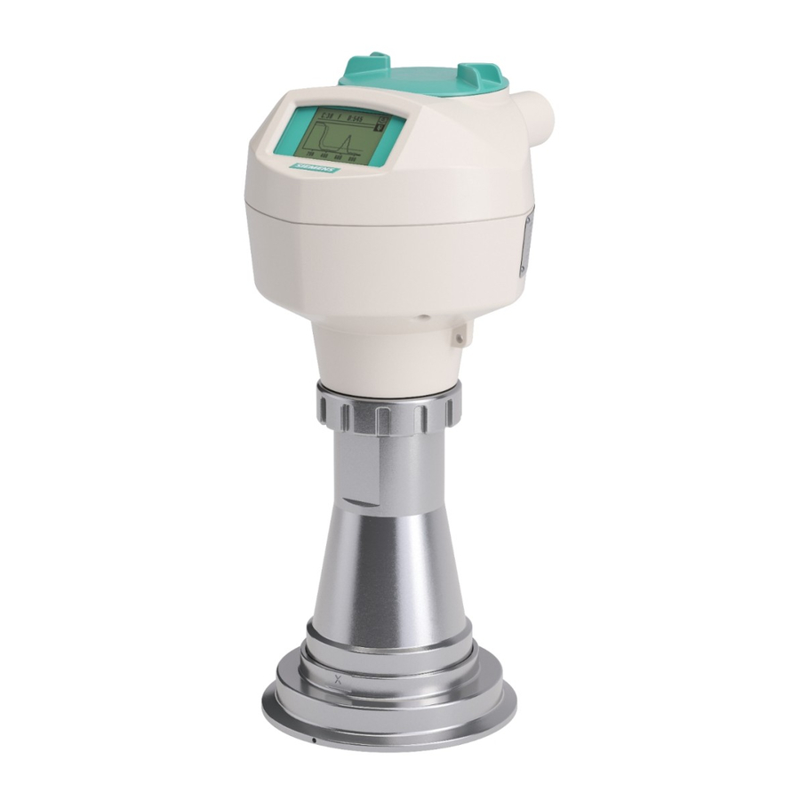
Radar Transmitters
SITRANS LR250 (PROFIBUS PA)
8 mm
Operating Instructions
A text area at the top is (big bar) 2-Spaltig, so the text extends upwards!
Then adjust the transparent beams according to and while holding the
8 mm distance from text.
I think this means that, if you need to add more lines of text, extend the big
bar upwards, while maintaining the proper distance from the text.
The lower pane (smal bar, Dokuklasse) must be only single-column!
Title page without bleed
in RGB
Find any font sizes for the text fields in the
Panel "Paragraph styles"!
Image should come behind the bar so that
the transparency comes to the fore.
Do not change the transparency of the bar!
Siemens Serif OT, Semibold, 36/30/26 PT, weiss
Absatzformat: 01 System 36/30/26 pt
Siemens Sans OT, Bold, 18/15/13 PT, weiss
Absatzformat: 02 Produkt 18/15/13 pt
Siemens Sans OT, Bold, 13/11 PT, weiss
Absatzformat: 03 Titel 13/11 pt
Siemens Sans OT, Bold, 13 PT, weiss
Absatzformat: 04 Dokuklasse 13 pt
Natural Blue dark CoolGray 100%
Edition
Siemens Sans OT, Bold, 11/7,5 pt, weiss
Absatzformat: 05 Ausgabe 11/7,5 pt
Siemens Sans OT, Bold, 13 PT, schwarz
Absatzformat: 06 SectorClaim 13 pt
08/2014
Advertisement
Table of Contents
Troubleshooting

Related Manuals for Siemens SITRANS LR250


Summary of Contents for Siemens SITRANS LR250
- Page 1 Background coolgray 20%, without history Image should come behind the bar so that the transparency comes to the fore. Do not change the transparency of the bar! Siemens Serif OT, Semibold, 36/30/26 PT, weiss Absatzformat: 01 System 36/30/26 pt 8 mm Radar Transmitters...
- Page 2 The user is responsible for all changes and repairs made to the device by the user or the user’s agent. All new components are to be provided by Siemens Milltronics Process Instruments. Restrict repair to faulty components only.
- Page 3 ___________________ Introduction ___________________ SITRANS LR250 (PROFIBUS PA) Safety information ___________________ Description ___________________ Installing/mounting ___________________ Connecting SITRANS ___________________ Commissioning ___________________ Radar Transmitters Remote operation SITRANS LR250 (PROFIBUS PA) ___________________ Parameter reference ___________________ Service and maintenance ___________________ Operating Instructions Diagnosing and troubleshooting...
- Page 4 Note the following: WARNING Siemens products may only be used for the applications described in the catalog and in the relevant technical documentation. If products and components from other manufacturers are used, these must be recommended or approved by Siemens. Proper transport, storage, installation, assembly, commissioning, operation and maintenance are required to ensure that the products operate safely and without any problems.
-
Page 5: Table Of Contents
CE Electromagnetic Compatibility (EMC) Conformity..............16 Improper device modifications ..................... 16 Requirements for special applications ..................17 Use in hazardous areas ....................... 17 Description ............................19 SITRANS LR250 overview ......................19 Programming ..........................20 Applications ..........................20 Approvals and certificates ......................20 Installing/mounting ..........................21 Basic safety information ....................... - Page 6 4.4.3 Hygienic versions ........................38 Disassembly ..........................39 Connecting ............................41 Basic safety information ......................41 Connecting SITRANS LR250 ...................... 42 Wiring setups for hazardous area installations ................45 5.3.1 Intrinsically safe wiring ........................ 46 5.3.1.1 Intrinsically safe wiring (FM/CSA) ....................47 5.3.1.2...
- Page 7 Communication troubleshooting ....................171 10.2 Device status icons ........................172 10.3 General fault codes ........................173 10.4 Operation troubleshooting ......................176 Technical data ............................ 179 11.1 Power ............................179 11.2 Performance ..........................179 SITRANS LR250 (PROFIBUS PA) Operating Instructions, 08/2014, A5E32221386-AC...
- Page 8 Hygienic encapsulated antenna (DN100 aseptic clamp to DIN 11864-3) ........ 214 12.22 Hygienic encapsulated antenna (Tuchenhagen Type N)............215 12.23 Hygienic encapsulated antenna (Tuchenhagen Type F) ............216 12.24 Threaded PVDF antenna ......................217 12.25 Threaded connection markings ....................218 SITRANS LR250 (PROFIBUS PA) Operating Instructions, 08/2014, A5E32221386-AC...
- Page 9 Analog Input Function Blocks 1 and 2 ..................261 Appendix C: Communications via PROFIBUS ..................265 Device configuration ........................265 C.1.1 SIMATIC PDM ..........................265 C.1.1.1 Electronic Device Description ....................265 Network configuration ........................ 265 SITRANS LR250 (PROFIBUS PA) Operating Instructions, 08/2014, A5E32221386-AC...
- Page 10 Acyclic data ..........................278 Appendix D: Certificates and Support ....................281 Certificates ..........................281 Technical support ........................281 List of abbreviations ..........................283 LCD menu structure ..........................285 Glossary .............................. 291 Index ..............................297 SITRANS LR250 (PROFIBUS PA) Operating Instructions, 08/2014, A5E32221386-AC...
-
Page 11: Introduction
Introduction LR250 PA manual usage Note This manual applies to the SITRANS LR250 (PROFIBUS PA) only. Follow these operating instructions for quick, trouble-free installation, and maximum accuracy and reliability of your device. We always welcome suggestions and comments about manual content, design, and accessibility. -
Page 12: Firmware Revision History
Antenna type parameter cannot be • modified. 1.02.02 1.02.00 24 May 2011 Threaded PVDF antenna supported. • 1.02.03 1.02.01 31 Oct 2012 Antenna parameter removed. • Quickstart on local display enhancements. • Electronic Device Description SITRANS LR250 (PROFIBUS PA) Operating Instructions, 08/2014, A5E32221386-AC... -
Page 13: Designated Use
4. Check the scope of delivery by comparing your order to the shipping documents for correctness and completeness. WARNING Using a damaged or incomplete device Danger of explosion in hazardous areas. • Do not use damaged or incomplete devices. SITRANS LR250 (PROFIBUS PA) Operating Instructions, 08/2014, A5E32221386-AC... -
Page 14: Transportation And Storage
The content reflects the technical status at the time of publishing. Siemens reserves the right to make technical changes in the course of further development. -
Page 15: Safety Information
WARNING: refer to accompanying documents (manual) for details. (Label on product: yellow background.) 2.1.2 Laws and directives Observe the test certification, provisions and laws applicable in your country during connection, assembly and operation. SITRANS LR250 (PROFIBUS PA) Operating Instructions, 08/2014, A5E32221386-AC... -
Page 16: Fcc Conformity
Improper device modifications Danger to personnel, system and environment can result from improper modifications to the device. • Changes or modifications not expressly approved by Siemens could void the user’s authority to operate the equipment. Note • This equipment has been tested and found to comply with the limits for a Class A digital device, pursuant to Part 15 of the FCC Rules. -
Page 17: Conformity With European Directives
R&TTE and the mutual recognition of their conformity. 1999/5/EC The applicable directives can be found in the EC conformity declaration of the specific device. SITRANS LR250 (PROFIBUS PA) Operating Instructions, 08/2014, A5E32221386-AC... -
Page 18: Ce Electromagnetic Compatibility (Emc) Conformity
Danger to personnel, system and environment can result from modifications to the device, particularly in hazardous areas. • Only carry out modifications that are described in the instructions for the device. Failure to observe this requirement cancels the manufacturer's warranty and the product approvals. SITRANS LR250 (PROFIBUS PA) Operating Instructions, 08/2014, A5E32221386-AC... -
Page 19: Requirements For Special Applications
Note Operation under special ambient conditions We highly recommend that you contact your Siemens representative or our application department before you operate the device under special ambient conditions as can be encountered in nuclear power plants or when the device is used for research and development purposes. - Page 20 Safety information 2.4 Use in hazardous areas SITRANS LR250 (PROFIBUS PA) Operating Instructions, 08/2014, A5E32221386-AC...
-
Page 21: Description
Loss of protection Danger to personnel, system and environment can result from improper use of the device. • SITRANS LR250 is to be used only in the manner outlined in this manual, otherwise protection provided by the device may be impaired. -
Page 22: Programming
Approvals and certificates Note For further details see Approvals (Page 185). SITRANS LR250 is available with approvals for General purpose, sanitary or hygienic and for hazardous areas. In all cases, check the nameplate on your device, and confirm the approval rating. -
Page 23: Installing/Mounting
Basic safety information Note Material compatibility Siemens can provide you with support concerning selection of sensor components wetted by process media. However, you are responsible for the selection of components. Siemens accepts no liability for faults or failures resulting from incompatible materials. -
Page 24: Pressure Applications
Hot, toxic and corrosive process media could be released. • Make sure that the device is suitable for the maximum permissible operating pressure of your system. SITRANS LR250 (PROFIBUS PA) Operating Instructions, 08/2014, A5E32221386-AC... -
Page 25: Pressure Equipment Directive, Ped, 97/23/Ec
• SITRANS LR250 units are hydrostatically tested, meeting or exceeding the requirement of the ASME Boiler and Pressure Vessel Code and the European Pressure Equipment Directive. -
Page 26: Installation Location Requirements
The device can overheat or materials become brittle due to UV exposure. • Protect the device from direct sunlight. • Make sure that the maximum permissible ambient temperature is not exceeded. Refer to the information in Chapter "Technical data". SITRANS LR250 (PROFIBUS PA) Operating Instructions, 08/2014, A5E32221386-AC... - Page 27 -40 to +120 °C (-40 to +248 °F) Note Details about the process connection, process temperature and materials are laser etched into the body of the flanged and hygienic versions. All other SITRANS LR250 versions have details listed on a tag. SITRANS LR250 (PROFIBUS PA)
-
Page 28: Proper Mounting
• When mounting, orient the front or back of the device towards the closest vessel wall or obstruction. • Do not rotate the enclosure after programming and vessel calibration, otherwise an error may occur, caused by a polarity shift of the transmit pulse. SITRANS LR250 (PROFIBUS PA) Operating Instructions, 08/2014, A5E32221386-AC... -
Page 29: Nozzle Design
DN150 (6"). Only shorter lengths are recommended for smaller diameters. ● When installing the SITRANS LR250 with hygienic process connection, it is good hygienic practice to install the antenna in a nozzle that has a maximum length/diameter ratio of 1:1. -
Page 30: Nozzle Location
● The peak energy density is directly in front of and in line with the antenna. ● There is a signal transmitted outside the beam angle, therefore false targets may be detected. SITRANS LR250 (PROFIBUS PA) Operating Instructions, 08/2014, A5E32221386-AC... - Page 31 Installing/mounting 4.3 Proper mounting Horn antenna Flanged encapsulated antenna Threaded PVDF antenna Hygienic encapsulated antenna ① Emission cone ② Beam angle SITRANS LR250 (PROFIBUS PA) Operating Instructions, 08/2014, A5E32221386-AC...
- Page 32 ● Keep emission cone free of interference from obstructions such as ladders, pipes, I-beams, or filling streams. Access for programming ● Provide easy access for viewing the display and programming via the handheld programmer. SITRANS LR250 (PROFIBUS PA) Operating Instructions, 08/2014, A5E32221386-AC...
-
Page 33: Orientation In A Vessel With Obstructions
For best results on a vessel with obstructions, or a stillpipe with openings, orient the front or back of the device toward the obstructions. For an illustration, see Device orientation (Page 33). ① Polarization axis ② Polarization reference point ③ Display SITRANS LR250 (PROFIBUS PA) Operating Instructions, 08/2014, A5E32221386-AC... -
Page 34: Mounting On A Stillpipe Or Bypass Pipe
> 100 mm (4") Bypass vent: Required at the upper end of the bypass To equalize pressure and keep the liquid level in the bypass constant with the liquid level in the vessel. SITRANS LR250 (PROFIBUS PA) Operating Instructions, 08/2014, A5E32221386-AC... -
Page 35: Device Orientation
Bypass pipe installation Stillpipe installation ① ① Vent Align front or back of device with stillpipe slots ② ② Align front or back of device with Slots vents Horn antenna version shown as example SITRANS LR250 (PROFIBUS PA) Operating Instructions, 08/2014, A5E32221386-AC... -
Page 36: Installation Instructions
The outer part of the lens on the flanged encapsulated antenna version may not appear to lie flush before installation and this is normal. This will flatten after installation and will not impact the performance of the device. SITRANS LR250 (PROFIBUS PA) Operating Instructions, 08/2014, A5E32221386-AC... -
Page 37: Threaded Versions
1. Before inserting the device into its mounting connection, check to ensure the threads are matching, to avoid damaging them. 2. Simply screw the device into the process connection, and hand tighten, or use a wrench. SITRANS LR250 (PROFIBUS PA) Operating Instructions, 08/2014, A5E32221386-AC... -
Page 38: Flanged Versions
30 – 50 3" 50 – 70 4" 40 – 60 6" 70 – 90 EN1092-1, PN16 / DN50/50A 30 – 50 JIS B 2220, 10K DN80/80A DN100/100A DN150/150A 60 – 80 SITRANS LR250 (PROFIBUS PA) Operating Instructions, 08/2014, A5E32221386-AC... - Page 39 For instructions on replacing the lens, see Part replacement (Page 167). See Flanged Horn with extension (Page 192), Raised-Face Flange per EN 1092-1 (Page 221), Flat-Face Flange (Page 224), and Flanged encapsulated antenna (3"/DN80/80A sizes and larger) (Page 198) for dimensions. SITRANS LR250 (PROFIBUS PA) Operating Instructions, 08/2014, A5E32221386-AC...
-
Page 40: Hygienic Versions
(for example, DIN 11864-3). Hygienic encapsulated antenna leak detection port ① Orientation mark for leak detection port ② Leak detection port SITRANS LR250 (PROFIBUS PA) Operating Instructions, 08/2014, A5E32221386-AC... -
Page 41: Disassembly
• If the device contains dangerous media, it must be emptied prior to disassembly. Make sure that no environmentally hazardous media are released. • Secure the remaining connections so that no damage can result if the process is started unintentionally. SITRANS LR250 (PROFIBUS PA) Operating Instructions, 08/2014, A5E32221386-AC... - Page 42 Installing/mounting 4.5 Disassembly SITRANS LR250 (PROFIBUS PA) Operating Instructions, 08/2014, A5E32221386-AC...
-
Page 43: Connecting
• Power plug: Ensure that the used socket has a PE/ground conductor connection. Check that the PE/ground conductor connection of the socket and power plug match each other. • Connecting terminals: Connect the terminals according to the terminal connection diagram. First connect the PE/ground conductor. SITRANS LR250 (PROFIBUS PA) Operating Instructions, 08/2014, A5E32221386-AC... -
Page 44: Connecting Sitrans Lr250
Connecting 5.2 Connecting SITRANS LR250 Connecting SITRANS LR250 WARNING Incorrect connection to power source Danger to personnel, system and environment can result from improper power connection. • The DC input terminals shall be supplied from a source providing electrical isolation between the input and output, in order to meet the applicable safety requirements of IEC 61010-1. - Page 45 (If cable is routed through conduit, use only approved suitable- size hubs for waterproof applications.) 2. Connect the wires to the terminals as shown: SITRANS LR250 (PROFIBUS PA) is not polarity sensitive. 3. Ground the device according to local regulations.
- Page 46 Connecting 5.2 Connecting SITRANS LR250 Note • PROFIBUS PA cable shield must be terminated at both ends of the cable for it to work properly. • If a Weidmüller or other current limiting junction box is connected to this device, please ensure that the current limit is set to 40 mA or higher.
-
Page 47: Wiring Setups For Hazardous Area Installations
PLC configuration with PROFIBUS PA for hazardous areas ① PLC (active) ② PC/laptop ③ Ex ia type DP/PA coupler ④ Ex ia device SITRANS LR250 (PROFIBUS PA) Operating Instructions, 08/2014, A5E32221386-AC... -
Page 48: Intrinsically Safe Wiring
Go to Support > Approvals / Certificates. The IECEx certificate listed on the nameplate can be viewed on the IECEx website. Go to: IECEx (http://iecex.iec.ch/) Click on Certified Equipment and enter the certificate number IECEx SIR 05.0031X. SITRANS LR250 (PROFIBUS PA) Operating Instructions, 08/2014, A5E32221386-AC... -
Page 49: Intrinsically Safe Wiring (Fm/Csa)
The FM/CSA Intrinsically Safe connection drawing number 23650675 can be downloaded from our website at: Product page (http://www.siemens.com/LR250) Go to Support > Installation Drawings > Level Measurement > SITRANS LR250. 5.3.1.2 Intrinsically safe wiring (notes) ● For wiring requirements: follow local regulations. - Page 50 A5E02358161 can be downloaded from our website at: Product page (http://www.siemens.com/LR250) Go to Support > Installation Drawings > Level Measurement > SITRANS LR250. The FISCO Concept allows interconnection of intrinsically safe apparatus to associated apparatus not specifically examined in such combination. The criteria for interconnection is that...
-
Page 51: Non-Sparking Wiring
FM/CSA Class 1, Div 2 connection drawing number 23650673 can be downloaded from our website: Product page (http://www.siemens.com/LR250) Go to Support > Installation Drawings > Level Measurement > SITRANS LR250. ● For wiring requirements: follow local regulations. ● Approved dust-tight and water-tight conduit seals are required for outdoor NEMA 4X / type 4X / NEMA 6, IP67, IP68 locations. -
Page 52: Instructions Specific To Hazardous Area Installations
– Aggressive substances: e.g. acidic liquids or gases that may attack metals, or solvents that may affect polymeric materials. – Suitable precautions: e.g. establishing from the material’s data sheet that it is resistant to specific chemicals. SITRANS LR250 (PROFIBUS PA) Operating Instructions, 08/2014, A5E32221386-AC... - Page 53 ● Aluminium, magnesium, titanium or zirconium may be used at the accessible surface of the equipment. In the event of rare incidents, ignition sources due to impact and friction sparks could occur. This shall be considered when the SITRANS LR250 PROFIBUS PA is being installed in locations that specifically require Equipment Protection level Ga or Da.
- Page 54 Connecting 5.4 Instructions specific to hazardous area installations SITRANS LR250 (PROFIBUS PA) Operating Instructions, 08/2014, A5E32221386-AC...
-
Page 55: Commissioning
• Do not expose to temperatures beyond the specified temperature range. • Do not incinerate. • Do not crush, puncture or open cells or disassemble. • Do not weld or solder to the battery’s body. • Do not expose contents to water. SITRANS LR250 (PROFIBUS PA) Operating Instructions, 08/2014, A5E32221386-AC... -
Page 56: Power Up
6.2 Operating via the handheld programmer 6.2.1 Power up Power up the device. A transition screen showing first the Siemens logo and then the current firmware revision is displayed while the first measurement is being processed. Press Mode to toggle between Measurement and Program mode. -
Page 57: The Lcd Display
7ML1930-1BK) (Page 57) for key functions in Measurement mode. Fault present ① Device status indicator, see Device status icons (Page 172) ② Text area displays a fault code and a status message SITRANS LR250 (PROFIBUS PA) Operating Instructions, 08/2014, A5E32221386-AC... - Page 58 ● A deeper band indicates fewer items. Parameter view Edit view ① ② ③ Parameter name Parameter number Parameter value/selection SITRANS LR250 (PROFIBUS PA) Operating Instructions, 08/2014, A5E32221386-AC...
-
Page 59: Handheld Programmer (Part No. 7Ml1930-1Bk)
RIGHT arrow opens PROGRAM mode Opens the top level menu. UP or DOWN arrow toggles between Identifies which AIFB is the source of the AIFB 1 and AIFB 2. displayed value. SITRANS LR250 (PROFIBUS PA) Operating Instructions, 08/2014, A5E32221386-AC... -
Page 60: Programming
For the complete list of parameters with instructions, see Parameter Reference (Page 107). Parameters are identified by name and organized into function groups. See LCD menu structure (Page 285). 1. QUICK START 2. SETUP 2.1. IDENTIFICATION .... 2.4. LINEARIZATION 2.4.1. VOLUME 2.4.1.1. VESSEL SHAPE SITRANS LR250 (PROFIBUS PA) Operating Instructions, 08/2014, A5E32221386-AC... - Page 61 • In navigation mode ARROW keys move to the next menu item in the direction of the arrow. • For Quick Access to parameters via the handheld programmer, press Home , then enter the menu number, for example: (2.4.1.) Volume. SITRANS LR250 (PROFIBUS PA) Operating Instructions, 08/2014, A5E32221386-AC...
- Page 62 Edit mode. The current selection is highlighted. Scroll to a new selection. ● Press RIGHT arrow to accept it. The LCD returns to parameter view and displays the new selection. ① Parameter name ② Parameter number ③ Current selection SITRANS LR250 (PROFIBUS PA) Operating Instructions, 08/2014, A5E32221386-AC...
- Page 63 ● Key in a new value. ● Press RIGHT arrow to accept it. The LCD returns to parameter view and displays the new selection. ① ② ③ Parameter name Parameter number Current value SITRANS LR250 (PROFIBUS PA) Operating Instructions, 08/2014, A5E32221386-AC...
- Page 64 Erases the display. editing Decimal point Numeric Enters a decimal point. editing Plus or minus sign Numeric Changes the sign of the entered value. editing Numeral Numeric Enters the corresponding character. editing SITRANS LR250 (PROFIBUS PA) Operating Instructions, 08/2014, A5E32221386-AC...
-
Page 65: Quick Start Wizard Via The Handheld Programmer
1.2 Material Selects the appropriate echo processing algorithms for the material [see Position Detect (2.5.7.2.) for more detail]. Options LIQUID LIQUID LOW DK (low dielectric liquid – CLEF algorithm enabled) dK < 3.0 SITRANS LR250 (PROFIBUS PA) Operating Instructions, 08/2014, A5E32221386-AC... - Page 66 High Calibration Point (process full level) ② ⑤ Level Sensor reference point ③ ⑥ Distance Low Calibration Point (process empty level) The point from which High and Low Calibration points are referenced: see Dimension Drawings. SITRANS LR250 (PROFIBUS PA) Operating Instructions, 08/2014, A5E32221386-AC...
-
Page 67: Auto False Echo Suppression
YES, NO, DONE (Display shows DONE when Quick Start is successfully completed.) Press Mode to return to Measurement mode. SITRANS LR250 is now ready to operate. 6.2.3.2 Auto False Echo Suppression If you have a vessel with known obstructions, we recommend using Auto False Echo Suppression to prevent false echo detection. -
Page 68: Requesting An Echo Profile
• To return to the previous menu, select Exit then press RIGHT arrow. ① ⑥ confidence measure ② algorithm: tF (trueFrist) ⑦ exit ③ ⑧ distance exit icon selected/highlighted ④ ⑨ exit icon deselected ⑤ echo SITRANS LR250 (PROFIBUS PA) Operating Instructions, 08/2014, A5E32221386-AC... -
Page 69: Device Address
YES to apply changes in the final step.) In each example, after performing a Quick Start, navigate to the other required parameters either via the handheld programmer or via SIMATIC PDM and enter the appropriate values. SITRANS LR250 (PROFIBUS PA) Operating Instructions, 08/2014, A5E32221386-AC... -
Page 70: Liquid Resin In Storage Vessel, Level Measurement
● High Calibration Pt.= 0.5 m (1.64 ft) from sensor reference point ● Max.fill/empty rate = 0.2 m/min (0.65 ft/min) In the event of a loss of echo: ● SITRANS LR250 is to report a user-defined value of 4.5 m (14.76 ft) after 2 minutes. ① ⑤... -
Page 71: Horizontal Vessel With Volume Measurement
Select vessel shape, Parabolic Ends, and enter values for A and L, to obtain a volume reading instead of level. In the event of a loss of echo: SITRANS LR250 is to report a user-defined value of 4.5 m (14.76 ft) after 2 minutes. - Page 72 6 m (19.68 ft) LOE Timer (2.3.6.) 2 minutes Mode (2.6.9.1.) Substitute value User-defined value to be used. Value (2.6.9.2.) 4.5 m (14.76 ft) Return to Measurement: press Mode to start normal operation. SITRANS LR250 (PROFIBUS PA) Operating Instructions, 08/2014, A5E32221386-AC...
-
Page 73: Application With Stillpipe
● High Calibration Pt. is 0.5 m (1.64 ft) from the sensor reference point. ● The stillpipe inside diameter is 50 mm (1.96"). ● The maximum rate of filling or emptying is about 0.1 m (4")/min. SITRANS LR250 (PROFIBUS PA) Operating Instructions, 08/2014, A5E32221386-AC... - Page 74 Low calibration point - 0.7 m = 4.3 m (14.1 ft) The recommended values for the propagation factor and for CLEF range are dependent on the stillpipe diameter. See Propagation Factor/Stillpipe Diameter for values. SITRANS LR250 (PROFIBUS PA) Operating Instructions, 08/2014, A5E32221386-AC...
- Page 75 Note Flanged and Hygienic encapsulated antenna For Flanged encapsulated antenna (7ML5432) and Hygienic encapsulated antenna (7ML5433) match the process connection size to the pipe diameter. For example, DN80/3" flange to DN80/3" pipe. SITRANS LR250 (PROFIBUS PA) Operating Instructions, 08/2014, A5E32221386-AC...
- Page 76 Commissioning 6.3 Application examples SITRANS LR250 (PROFIBUS PA) Operating Instructions, 08/2014, A5E32221386-AC...
-
Page 77: Remote Operation
The menu structure for SIMATIC PDM is almost identical to that for the LCD. See Parameters accessed via pull-down menus (Page 84) for parameters that do not appear in the menu structure in SIMATIC PDM. SITRANS LR250 (PROFIBUS PA) Operating Instructions, 08/2014, A5E32221386-AC... -
Page 78: Features Of Simatic Pdm Rev. 6.0, Sp4 Or Higher
Electronic Device Description (EDD) 7.1.2.1 Updating the Electronic Device Description (EDD) You can locate the EDD in Device Catalog, under Sensors/Level/Echo/SiemensMilltronics/SITRANS LR250. The EDD revision must match the Firmware revision in the device. SITRANS LR250 (PROFIBUS PA) Operating Instructions, 08/2014, A5E32221386-AC... -
Page 79: Configuring A New Device
4. Open the menu Device – Master Reset and click on Factory Defaults. 5. After the reset is complete click on Close, then upload parameters to the PC/PG. 6. Configure the device via the Quick Start wizard. SITRANS LR250 (PROFIBUS PA) Operating Instructions, 08/2014, A5E32221386-AC... -
Page 80: Quick Start Wizard Via Simatic Pdm
• For a vessel with obstructions see Auto False Echo Suppression via SIMATIC PDM (Page 87). Launch SIMATIC PDM, open the menu Device – Wizard - Quick Start, and follow steps 1 to 5. ① Quick Start SITRANS LR250 (PROFIBUS PA) Operating Instructions, 08/2014, A5E32221386-AC... - Page 81 PC/PG and ensure PDM is synchronized with the device. 2. If required, change the language for the local user interface. 3. Click on NEXT to accept the default values. (Description, Message, and Installation Date fields can be left blank.) SITRANS LR250 (PROFIBUS PA) Operating Instructions, 08/2014, A5E32221386-AC...
- Page 82 7.1 Operating via SIMATIC PDM Step 2 – Application Select the application type (level or volume) and the material, then click on NEXT. See Application with Stillpipe (Page 71) for a Low Dielectric Liquid application. SITRANS LR250 (PROFIBUS PA) Operating Instructions, 08/2014, A5E32221386-AC...
- Page 83 Step 3 – Vessel Shape The vessel shapes shown are predefined. For a vessel with obstructions, see Auto False Echo Suppression via SIMATIC PDM (Page 87). Select the vessel shape, and click on NEXT. SITRANS LR250 (PROFIBUS PA) Operating Instructions, 08/2014, A5E32221386-AC...
- Page 84 Check parameter settings, and click on BACK to return and revise values, FINISH to save settings offline, or FINISH AND DOWNLOAD to save settings offline and transfer them to the device. The message Quick Start was successful will appear. Click on OK. SITRANS LR250 (PROFIBUS PA) Operating Instructions, 08/2014, A5E32221386-AC...
-
Page 85: Changing Parameter Settings Using Simatic Pdm
2. Adjust parameter values in the parameter value field then Enter. The status fields read Changed. 3. Open the Device menu, click on Download to device, then use File - Save to save settings offline. The status fields are cleared. ① value fields SITRANS LR250 (PROFIBUS PA) Operating Instructions, 08/2014, A5E32221386-AC... -
Page 86: Parameters Accessed Via Pull-Down Menus
Open the menu Device – Echo Profile Utilities and click on the appropriate tab for easy access ● Echo profile (Page 85) ● View Saved Echo Profiles (Page 86) ● TVT Shaper (Page 86) ● Auto False Echo Suppression (Page 87) ● Echo Setup (Page 90) SITRANS LR250 (PROFIBUS PA) Operating Instructions, 08/2014, A5E32221386-AC... - Page 87 For faster and more coarse views, the Standard resolution may be used. ● Click Save and in the new window enter a name and click OK. ● Click OK to exit. ① Resolution ② Echo Profile Time Based Storage SITRANS LR250 (PROFIBUS PA) Operating Instructions, 08/2014, A5E32221386-AC...
- Page 88 This feature allows you to manually adjust the TVT to avoid false echoes caused by obstructions. For an explanation see Auto False Echo Suppression (Page 236). Open the menu Device – Echo Profile Utilities and click the tab TVT Shaper. SITRANS LR250 (PROFIBUS PA) Operating Instructions, 08/2014, A5E32221386-AC...
-
Page 89: Auto False Echo Suppression
• Set Auto False Echo Suppression and Auto False Echo Suppression Range during startup, if possible. • If the vessel contains an agitator it should be running. • Before adjusting these parameters, rotate the device for best signal (lower false-echo amplitude). SITRANS LR250 (PROFIBUS PA) Operating Instructions, 08/2014, A5E32221386-AC... - Page 90 8. To turn Auto False Echo Suppression off or on, reopen the Auto False Echo Suppression window, change the Auto False Echo Suppression to Off or On, click on Transfer to Device. SITRANS LR250 (PROFIBUS PA) Operating Instructions, 08/2014, A5E32221386-AC...
- Page 91 Default TVT Material level ③ False echo After Auto False Echo Suppression ① ④ False echo Material level ② ⑤ Learned TVT Default TVT ③ ⑥ Auto False Echo Suppression Range Echo marker SITRANS LR250 (PROFIBUS PA) Operating Instructions, 08/2014, A5E32221386-AC...
-
Page 92: Echo Setup
Open the menu Device – Echo Profile Utilities and click on Echo Setup. 7.1.5.4 Maintenance You can set schedules and reminders for: ● device maintenance based on its projected lifetime ● sensor maintenance based on its projected lifetime ● service ● calibration SITRANS LR250 (PROFIBUS PA) Operating Instructions, 08/2014, A5E32221386-AC... - Page 93 2. Modify desired values and if desired, set reminders for either or both of Reminder 1 before Lifetime (Required)/Reminder 2 before Lifetime (Demanded). 3. Click Write. 4. Click Read, to see the effects of your modification. 5. Click Service/Calibration Performed to reset the schedule. SITRANS LR250 (PROFIBUS PA) Operating Instructions, 08/2014, A5E32221386-AC...
-
Page 94: Acknowledge Faults
Analog Input Function Blocks 1 and 2 (Page 261). Simulate analog input to AIFB1 or AIFB2 Allows you to input a simulated measured value, status, and quality, in order to test the functioning of an Analog Input Function Block. SITRANS LR250 (PROFIBUS PA) Operating Instructions, 08/2014, A5E32221386-AC... - Page 95 4. The Output value from the desired function block is displayed in PDM, and the LCD displays the substitute value. See Simulate Output below, to set the output mode. 5. After simulation is complete, disable simulation and click on Transfer. SITRANS LR250 (PROFIBUS PA) Operating Instructions, 08/2014, A5E32221386-AC...
- Page 96 2. Select Manual Mode (from options AUTO, Manual, or Out of Service) and click on Transfer. 3. Enter simulated value and click on Transfer. 4. After simulation is complete, return to Simulate Output, reselect AUTO mode, and click on Transfer. SITRANS LR250 (PROFIBUS PA) Operating Instructions, 08/2014, A5E32221386-AC...
-
Page 97: Write Locking
To enable/disable Write Locking 1. Open the menu Device – Write Locking and turn Write Protection On or Off. 2. Click on Transfer. SITRANS LR250 (PROFIBUS PA) Operating Instructions, 08/2014, A5E32221386-AC... -
Page 98: Master Reset
1. Open the menu Device – Master Reset and click on Reset Address to 126. 2. Click on OK: the address will be reset to 126, and if the address lock was on, it will be disabled. SITRANS LR250 (PROFIBUS PA) Operating Instructions, 08/2014, A5E32221386-AC... -
Page 99: Diagnostics
To view peak sensor values, peak FB1 and FB2 values, or peak electronics temperatures, see Device Diagnostics (Page 100). ● Sensor Value and simulation setting ● Electronics temperature ● Measured Value (level, volume, and distance) together with quality and status. SITRANS LR250 (PROFIBUS PA) Operating Instructions, 08/2014, A5E32221386-AC... - Page 100 Open the menu View – Process Variables and click on Function Blocks to view the channel (level, volume, space, or distance), operating mode (Auto, Manual, or Out of Service), quality, status, simulation setting, and summary of alarms. SITRANS LR250 (PROFIBUS PA) Operating Instructions, 08/2014, A5E32221386-AC...
- Page 101 7.1 Operating via SIMATIC PDM Trend view Open the menu View – Process Variables and click on Trend View to monitor Sensor Value and values for AIFB1 and AIFB2. ① trend line ② trend lines SITRANS LR250 (PROFIBUS PA) Operating Instructions, 08/2014, A5E32221386-AC...
- Page 102 Status, Extended Diagnostics, and Maintenance. Diagnostics In the Device Status window, click on the Diagnostics tab, then on the Update diagnostics button, to update diagnostic information and refresh linked icons. ① Update diagnostics SITRANS LR250 (PROFIBUS PA) Operating Instructions, 08/2014, A5E32221386-AC...
- Page 103 Remote operation 7.1 Operating via SIMATIC PDM Device Status Click on the Device Status tab to view peak sensor values, peak FB1 and FB2 values, and peak electronics temperatures. SITRANS LR250 (PROFIBUS PA) Operating Instructions, 08/2014, A5E32221386-AC...
- Page 104 Open the menu View – Device Diagnostics and go to Analog Input 1/Analog Input 2. Click on the tab Overview to see the status of all warnings and alarms. Click on the tab Alarms and Warnings for details. Update Open the menu View – Update to refresh the screen. SITRANS LR250 (PROFIBUS PA) Operating Instructions, 08/2014, A5E32221386-AC...
- Page 105 1. Open a project, double-click on the device icon, and in the User window select Specialist. 2. Open the menu Options – Settings and click on the Password tab. 3. Enter a new password and re-enter it in the Confirmation window. Click on OK. SITRANS LR250 (PROFIBUS PA) Operating Instructions, 08/2014, A5E32221386-AC...
-
Page 106: Operating Via Fdt
EDD is independent of the operating system. 7.2.2 SITRANS DTM ● SITRANS DTM is an EDDL interpreter developed by Siemens to interpret the EDD for that device. ● To use SITRANS DTM to connect to a device, you must first install SITRANS DTM on your system and then install the device EDD written for SITRANS DTM. -
Page 107: The Device Edd
Remote operation 7.2 Operating via FDT 7.2.3 The device EDD The SITRANS LR250 PROFIBUS PA EDD for SITRANS DTM can be downloaded from our website: Product page (http://www.siemens.com/LR250). Go to Support > Software Downloads. 7.2.4 Configuring a new device via FDT The full process to configure a field device via FDT is outlined in an Application Guide which can be downloaded from our website under Support >... - Page 108 Remote operation 7.2 Operating via FDT SITRANS LR250 (PROFIBUS PA) Operating Instructions, 08/2014, A5E32221386-AC...
-
Page 109: Parameter Reference
Quick Start has been completed.) • For access via remote operation see Quick Start Wizard via SIMATIC PDM (Page 78). • For detailed instructions see Quick Start Wizard via the handheld programmer (Page 63). SITRANS LR250 (PROFIBUS PA) Operating Instructions, 08/2014, A5E32221386-AC... - Page 110 Setup (2.) Note • Default settings in the parameter tables are indicated with an asterisk (*) unless explicitly stated. • Values shown in the following tables can be entered via the handheld programmer. SITRANS LR250 (PROFIBUS PA) Operating Instructions, 08/2014, A5E32221386-AC...
- Page 111 Read only. Corresponds to the software or firmware that is embedded in the Field Device. Loader Revision (2.2.3.) Read only. Corresponds to the software used to update the Field Device. Order Option (2.2.4.) Read only. Displays the device type. SITRANS LR250 (PROFIBUS PA) Operating Instructions, 08/2014, A5E32221386-AC...
- Page 112 Volume values liter, gal Percent value Temperature Units (2.3.4.) Selects the engineering unit to be displayed with the value representing temperature. Options DEG C, DEG F, RANKINE, KELVIN DEG C SITRANS LR250 (PROFIBUS PA) Operating Instructions, 08/2014, A5E32221386-AC...
- Page 113 Sets the time to elapse since the last valid reading, before the Fail-safe material level is reported. Values Range: 0 to 720 seconds Default: 100 s Calibration (2.3.7) Note We recommend using the Quick Start wizard to configure the device. SITRANS LR250 (PROFIBUS PA) Operating Instructions, 08/2014, A5E32221386-AC...
- Page 114 The value produced by the echo processing which represents the distance from sensor reference point to the target. [see Threaded Horn Antenna with extension, (Page 190) Flanged Horn with extension (Page 194), and Flanged encapsulated antenna (3"/DN80/80A sizes and larger) (Page 198)]. SITRANS LR250 (PROFIBUS PA) Operating Instructions, 08/2014, A5E32221386-AC...
- Page 115 A constant offset that can be added to Level. The unit is defined in Level units. Values Range: -999999.00 to 999999.00. Default: 0% Rate (2.3.8.) Note Default settings in the parameter tables are indicated with an asterisk (*) unless explicitly stated. SITRANS LR250 (PROFIBUS PA) Operating Instructions, 08/2014, A5E32221386-AC...
- Page 116 Defines the maximum rate at which the reported sensor value is allowed to decrease. Allows you to adjust the SITRANS LR250 response to decreases in the actual material level. Fill Rate is automatically updated whenever Response rate (2.3.8.1.) is altered.
- Page 117 Flat end horizontal cylinder SPHERE/ Maximum volume Sphere LINEAR/ Maximum volume Upright, linear (flat bottom) CONICAL BOT/ Maximum volume, Conical or pyramidal dimension A bottom PARABOLIC Maximum volume, BOT/Parabolic bottom dimension A SITRANS LR250 (PROFIBUS PA) Operating Instructions, 08/2014, A5E32221386-AC...
- Page 118 Vessel Shape (2.4.1.1.) For readings in volumetric units instead of percentage values: 1. Select a volumetric unit from PV Units (volume/level) (2.3.3.). 2. Enter the vessel volume corresponding to High Calibration Point. SITRANS LR250 (PROFIBUS PA) Operating Instructions, 08/2014, A5E32221386-AC...
- Page 119 Enter up to 32 level breakpoints, where the corresponding volume is known. The values corresponding to 100% and 0% levels must be entered. The breakpoints can be ordered from top to bottom, or the reverse. SITRANS LR250 (PROFIBUS PA) Operating Instructions, 08/2014, A5E32221386-AC...
- Page 120 5. Go to Y value (2.4.1.7.) and enter the volume value for the breakpoint just identified. 6. Repeat steps 3 to 5 until values have been entered for all required breakpoints. X value (2.4.1.6.) Y value (2.4.1.7.) SITRANS LR250 (PROFIBUS PA) Operating Instructions, 08/2014, A5E32221386-AC...
- Page 121 Default: Value for Low Calibration Pt. + 1 m (3.28 ft) Related parameters Units (2.3.1.) Use this feature if the measured surface can drop below the Low calibration point in normal operation. SITRANS LR250 (PROFIBUS PA) Operating Instructions, 08/2014, A5E32221386-AC...
- Page 122 700 or 1000 mm Note Flanged encapsulated antenna For Flanged encapsulated antenna (7ML5432) match the process connection size to the pipe diameter whenever possible (for example, mount a DN80/3" flange on DN80/3" pipe). SITRANS LR250 (PROFIBUS PA) Operating Instructions, 08/2014, A5E32221386-AC...
- Page 123 3, we recommend setting Position Detect to Hybrid and CLEF Range (2.5.7.4.) to 0.5 m (1.64 ft). SITRANS LR250 (PROFIBUS PA) Operating Instructions, 08/2014, A5E32221386-AC...
- Page 124 Sensor reference point ③ Low calibration point (process empty level) In applications with low dK materials we recommend setting CLEF Range to 0.5 m (1.64 ft) and Position Detect (2.5.7.2.) to Hybrid. SITRANS LR250 (PROFIBUS PA) Operating Instructions, 08/2014, A5E32221386-AC...
- Page 125 Echo Lock (2.5.8.1.) Note Ensure the agitator is always running while SITRANS LR250 is monitoring the vessel, to avoid stationary blade detection. Selects the measurement verification process. See Echo Lock (2.5.8.1.) for more details.
- Page 126 Open the menu Device – Echo Profile Utilities and click on the tab Echo Profile. TVT Setup (2.5.10.) Note Default settings in the parameter tables are indicated with an asterisk (*) unless explicitly stated. SITRANS LR250 (PROFIBUS PA) Operating Instructions, 08/2014, A5E32221386-AC...
- Page 127 • Before adjusting these parameters, rotate the device for best signal (lower false-echo amplitude). Before Auto False Echo Suppression ① ④ TVT Hover Level echo marker ② ⑤ default TVT material level ③ false echo SITRANS LR250 (PROFIBUS PA) Operating Instructions, 08/2014, A5E32221386-AC...
- Page 128 4. Go to Auto False Echo Suppression (2.5.10.1.) and press RIGHT arrow to open Edit Mode. 5. Select Learn. The device will automatically revert to On (Use Learned TVT) after a few seconds. SITRANS LR250 (PROFIBUS PA) Operating Instructions, 08/2014, A5E32221386-AC...
- Page 129 When the device is located in the center of the vessel, the TVT hover level may be lowered to increase the confidence level of the largest echo. Shaper Mode (2.5.10.4.) Enables/disables TVT shaper (2.5.11.) Options SITRANS LR250 (PROFIBUS PA) Operating Instructions, 08/2014, A5E32221386-AC...
- Page 130 Range: –50 to 50 dB Default: 0 dB Breakpoint 10-18 (2.5.11.2.) Values Range: –50 to 50 dB Default: 0 dB Breakpoint 19-27 (2.5.11.3.) Values Range: –50 to 50 dB Default: 0 dB SITRANS LR250 (PROFIBUS PA) Operating Instructions, 08/2014, A5E32221386-AC...
- Page 131 Manual Mode (MAN) Out of Service (O/S) Allows you to put the SITRANS LR250 into Out of Service Mode and then reset it to Auto Mode. Manual Mode is used in conjunction with Simulation. See Simulation (Page 92). It should be used only with SIMATIC PDM in order to benefit from all the features available.
- Page 132 Defines the operational lower range value of the input value (Process Value Scale) in PV (volume/level) Units. Process Value Scale normalizes the input value to a customer-defined range. Values Range: -999999 to 999999 Default: 0% SITRANS LR250 (PROFIBUS PA) Operating Instructions, 08/2014, A5E32221386-AC...
- Page 133 The setting for the upper alarm limit in AIFB1 units. Values Range: -999999 to 999999 Default: 999999 Upper Limit Warning (2.6.7.2.) The setting for the upper warning limit in AIFB1 units. Values Range: -999999 to 999999 Default: 999999 SITRANS LR250 (PROFIBUS PA) Operating Instructions, 08/2014, A5E32221386-AC...
- Page 134 This is an exponential filter and the engineering unit is always in seconds. See Damping (Page 239) for more detail. Values Range: 0 to 600 s Default: 10 s SITRANS LR250 (PROFIBUS PA) Operating Instructions, 08/2014, A5E32221386-AC...
- Page 135 (Loss of Echo) timer expires. Options SUB VALUE Substitute value. Value (2.6.9.2.) used as output value. LAST VALUE Last value. (Store last valid output value). USE BAD Use bad value. (Calculated output value is VALUE incorrect). SITRANS LR250 (PROFIBUS PA) Operating Instructions, 08/2014, A5E32221386-AC...
- Page 136 The value for level, or volume (if volume conversion is selected). Output, no linearization (SV1 - Secondary Value 1) (2.8.2.) The value for level. Output, no level offset (SV2 - Secondary Value 2) (2.8.3.) The value for distance. SITRANS LR250 (PROFIBUS PA) Operating Instructions, 08/2014, A5E32221386-AC...
- Page 137 Material level 1. Navigate to Level Meter > Diagnostics (3.) > Echo Profile (3.1.). 2. Press RIGHT arrow to request a profile. [See Requesting an Echo Profile (Page 66) for more details.] SITRANS LR250 (PROFIBUS PA) Operating Instructions, 08/2014, A5E32221386-AC...
- Page 138 3. Click on Transfer to clear the fault. Electronics Temperature (3.3.) Minimum Value (3.3.1.) The minimum recorded internal electronics temperature of the SITRANS LR250. Maximum Value (3.3.2.) The maximum recorded internal electronics temperature of the SITRANS LR250. SITRANS LR250 (PROFIBUS PA)
- Page 139 Select Yes or No to enable/disable Condensed Mode. Features supported (3.4.2.) Read only. Features supported are: ● Condensed Diagnostics ● Extended Diagnostics ● Application Relationships Features enabled (view only) (3.4.3.) Read only. Lists those features that have been enabled. SITRANS LR250 (PROFIBUS PA) Operating Instructions, 08/2014, A5E32221386-AC...
- Page 140 2. Go to Diagnostics > Condensed Status. 3. For each event, you can select either the Status or the Diagnosis line, then choose a Status or Diagnosis option from the associated pull-down menu. SITRANS LR250 (PROFIBUS PA) Operating Instructions, 08/2014, A5E32221386-AC...
- Page 141 Condensed Status Mode. 2. Go to Level Meter > Diagnostics > Condensed Status. 3. Select the Status line for the selected Event, then choose a Status option from the associated pull-down menu. SITRANS LR250 (PROFIBUS PA) Operating Instructions, 08/2014, A5E32221386-AC...
- Page 142 Min. Measured Value (3.6.1.) The minimum recorded Sensor value, reported in units defined in Unit (2.3.1.). Max. Measured Value (3.6.2.) The maximum recorded Sensor value, reported in units defined in Unit (2.3.1.). SITRANS LR250 (PROFIBUS PA) Operating Instructions, 08/2014, A5E32221386-AC...
- Page 143 Maximum Output Value - AIFB2 (3.6.6.) The maximum recorded Output Value from the Analog Input Function Block 2. Service (4.) Note Default settings in the parameter tables are indicated with an asterisk (*) unless explicitly stated. SITRANS LR250 (PROFIBUS PA) Operating Instructions, 08/2014, A5E32221386-AC...
- Page 144 To perform a reset via the handheld programmer: 1. Press RIGHT Arrow to open Edit Mode then scroll down to the desired Reset option and press RIGHT Arrow to select it. 2. Press LEFT Arrow to exit. SITRANS LR250 (PROFIBUS PA) Operating Instructions, 08/2014, A5E32221386-AC...
- Page 145 (via SIMATIC PDM only) see Lifetime Expected (4.2.1.). The device tracks itself based on operating hours and monitors its predicted lifetime. You can modify the expected device lifetime, set up schedules for maintenance reminders, and acknowledge them. SITRANS LR250 (PROFIBUS PA) Operating Instructions, 08/2014, A5E32221386-AC...
- Page 146 ● Click on Snooze to add a year to the Total Expected Device Life. Time Units Options Hours; days; years Default: years Selectable only via SIMATIC PDM. SITRANS LR250 (PROFIBUS PA) Operating Instructions, 08/2014, A5E32221386-AC...
- Page 147 Reminder 1 (Maintenance Required) Reminder 2 (Maintenance Demanded) Reminders 1 and 2 1. First set the values in Reminder 1 (Required) (4.2.5.)/Reminder 2 (Demanded) (4.2.6.). 2. Select the desired Reminder Activation option. SITRANS LR250 (PROFIBUS PA) Operating Instructions, 08/2014, A5E32221386-AC...
- Page 148 2. In the Device Lifetime section, click on Acknowledge Warnings. To acknowledge a reminder via the handheld programmer: 1. Press RIGHT arrow twice to open parameter view and activate Edit Mode. 2. Press RIGHT arrow to acknowledge the reminder. SITRANS LR250 (PROFIBUS PA) Operating Instructions, 08/2014, A5E32221386-AC...
- Page 149 ● Click on Snooze to add a year to the Total Expected Sensor Life. ● Click on Sensor Replaced to restart the timer and clear any fault messages. Time Units Options Hours; days; years Default: years Selectable only via SIMATIC PDM. SITRANS LR250 (PROFIBUS PA) Operating Instructions, 08/2014, A5E32221386-AC...
- Page 150 Reminder 1 (Maintenance Required) Reminder 2 (Maintenance Demanded) Reminders 1 and 2 1. First set the values in Reminder 1 (Required) (4.3.5.)/Reminder 2 (Demanded) (4.3.6.). 2. Select the desired Reminder Activation option. SITRANS LR250 (PROFIBUS PA) Operating Instructions, 08/2014, A5E32221386-AC...
- Page 151 2. In the Sensor Lifetime section, click on Acknowledge Warnings. To acknowledge a reminder via the handheld programmer: 1. Press RIGHT arrow twice to open parameter view and activate Edit Mode. 2. Press RIGHT arrow to acknowledge the reminder. SITRANS LR250 (PROFIBUS PA) Operating Instructions, 08/2014, A5E32221386-AC...
- Page 152 ● Click on Service Performed to restart the timer and clear any fault messages. Time Units Options Hours; days; years Default: years Selectable only via SIMATIC PDM. SITRANS LR250 (PROFIBUS PA) Operating Instructions, 08/2014, A5E32221386-AC...
- Page 153 ON - Reminders 1 and 2 checked ON - Reminder 2 (Maintenance Demanded) checked 1. First set the values in Reminder 1 (Required) (4.4.5.)/Reminder 2 (Demanded) (4.4.6.). 2. Select the desired Reminder Activation option. SITRANS LR250 (PROFIBUS PA) Operating Instructions, 08/2014, A5E32221386-AC...
- Page 154 2. In the Service Schedule Status section, click on Acknowledge Warnings. To acknowledge a reminder via the handheld programmer: 1. Press RIGHT arrow twice to open parameter view and activate Edit Mode. 2. Press RIGHT arrow to acknowledge the reminder. SITRANS LR250 (PROFIBUS PA) Operating Instructions, 08/2014, A5E32221386-AC...
- Page 155 ● Click on Calibration Performed to restart the timer and clear any fault messages. Time Units Options Hours; days; years Default: years Selectable only via SIMATIC PDM. SITRANS LR250 (PROFIBUS PA) Operating Instructions, 08/2014, A5E32221386-AC...
- Page 156 ON - Reminders 1 and 2 checked ON—Reminder 2 (Maintenance Demanded) checked 1. First set the values in Reminder 1 (Required) (4.5.5.)/Reminder 2 (Demanded) (4.5.6.). 2. Select the desired Reminder Activation option. SITRANS LR250 (PROFIBUS PA) Operating Instructions, 08/2014, A5E32221386-AC...
- Page 157 2. In the Calibration Schedule Status section click on Acknowledge Warnings. To acknowledge a reminder via the handheld programmer: 1. Press RIGHT arrow twice to open parameter view and activate Edit Mode. 2. Press RIGHT arrow to acknowledge the reminder. SITRANS LR250 (PROFIBUS PA) Operating Instructions, 08/2014, A5E32221386-AC...
- Page 158 Parameter reference Manufacture Date (4.6.) Read only. The date of manufacture of the SITRANS LR250 (yy mm dd). Powered Hours (4.7.) Read only. Displays the number of hours the unit has been powered up since manufacture. In SIMATIC PDM, open the menu Device – Wear.
- Page 159 STD PROFILE Standard Profile (uses generic GSD for 2 AIFB) [ident # = 0x9701] MANUFACTURER Manufacturer-specific (uses Siemens EDD and GSD file, which identifies the LR250 PROFIBUS PA [ident # = 0x8150] STD – AIFB 1 Standard Profile AIFB 1 only (uses generic GSD ONL.
- Page 160 Prevents any changes to parameters via PDM or the hand-held programmer. Hand-held Range: 0 to 99999. Default: Off programmer values 2457 (unlock value) Off (enables programming) any other value On (disables programming) SITRANS LR250 (PROFIBUS PA) Operating Instructions, 08/2014, A5E32221386-AC...
- Page 161 In SIMATIC PDM, open the menu Device – Write Locking, select On or Off, and click on Transfer. Language (7.) Selects the language to be used on the LCD. Options English Deutsch Français Español SITRANS LR250 (PROFIBUS PA) Operating Instructions, 08/2014, A5E32221386-AC...
-
Page 162: Alphabetical Parameter List
Dimension L (2.4.1.4.) Display (2.6.8.) Echo Lock (2.5.8.1.) Echo Profile (3.1.) Echo Quality (2.5.9.) Echo Select (2.5.7.) Echo Strength (2.5.9.2.) Electronics Temperature (3.3.) Empty rate (2.3.8.3.) Event Index (3.5.1.) Event Status (3.5.2.) SITRANS LR250 (PROFIBUS PA) Operating Instructions, 08/2014, A5E32221386-AC... - Page 163 Local Operation (6.2.2.) LOE Timer (2.3.6.) Low Calibration Pt. (2.3.7.1.) Lower Limit Warning (2.6.7.3.) Lower Limit Alarm (2.6.7.4.) Low Level Point (2.3.7.4.) Main Output (PV– Primary Value) (2.8.1.) Material (2.3.5.) Master Reset (4.1.) SITRANS LR250 (PROFIBUS PA) Operating Instructions, 08/2014, A5E32221386-AC...
- Page 164 PROFIBUS Ident Number (5.2.) Propagation Factor (2.5.3.) PV Units (volume/level) (2.3.3.) Quick Start (1.) Rate (2.3.8.) Remaining Device Lifetime (4.2.) Remaining Sensor Lifetime (4.3.) Remote Access (6.1.) Remote Lockout (6.1.1.) Response Rate (2.3.8.1.) SITRANS LR250 (PROFIBUS PA) Operating Instructions, 08/2014, A5E32221386-AC...
- Page 165 TVT shaper (2.5.11.) Upper Limit Warning (2.6.7.2.) Upper Limit Alarm (2.6.7.1.) Unit (2.3.1.) Value (2.6.9.2.) Vessel Shape (2.4.1.1.) Volume (2.4.1.) Write Protection (6.2.1.) XY index (2.4.1.5.) X value (2.4.1.6.) Y value (2.4.1.7.) SITRANS LR250 (PROFIBUS PA) Operating Instructions, 08/2014, A5E32221386-AC...
- Page 166 Parameter reference SITRANS LR250 (PROFIBUS PA) Operating Instructions, 08/2014, A5E32221386-AC...
-
Page 167: Service And Maintenance
Service and maintenance Basic safety information WARNING Impermissible repair of the device • Repair must be carried out by Siemens authorized personnel only. CAUTION Releasing key lock Improper modification of parameters could influence process safety. • Make sure that only authorized personnel may cancel the key locking of devices for safety-related applications. -
Page 168: Maintenance And Repair Work
• If working on an energized device is necessary, ensure that the environment is dry. • Make sure when carrying out cleaning and maintenance work that no moisture penetrates the inside of the device. SITRANS LR250 (PROFIBUS PA) Operating Instructions, 08/2014, A5E32221386-AC... -
Page 169: Unit Repair And Excluded Liability
Replacing the antenna Changing to a different antenna type may be performed by a Siemens authorized repair center or personnel. If the electronics or enclosure require replacement due to damage or failure, please ensure the correct antenna version is used, otherwise a re-calibration will need to be performed by Siemens authorized personnel. - Page 170 Tuchenhagen, Hygienic encapsulated antenna Lens and silicon Type F A5E32572794 O-ring Type N A5E32572795 Note For more information about accessories such as clamps, seals and process connections, please see the catalog on the product page (http://www.siemens.com/LR250). SITRANS LR250 (PROFIBUS PA) Operating Instructions, 08/2014, A5E32221386-AC...
-
Page 171: Disposal
Service and maintenance 9.4 Disposal Disposal Note Special disposal required The device includes components that require special disposal. • Dispose of the device properly and environmentally through a local waste disposal contractor. SITRANS LR250 (PROFIBUS PA) Operating Instructions, 08/2014, A5E32221386-AC... - Page 172 Service and maintenance 9.4 Disposal SITRANS LR250 (PROFIBUS PA) Operating Instructions, 08/2014, A5E32221386-AC...
-
Page 173: Diagnosing And Troubleshooting
Make sure Write Protection (6.2.1.) is set to the • handheld programmer. unlock value. You try to set a SITRANS LR250 Ensure Remote Lockout (6.1.1.) is disabled. • parameter via remote communications but Ensure Write Protection (6.2.1.) is set to the unlock •... -
Page 174: Device Status Icons
Communication is good; device is in simulation mode or works with substitute values. • Out of operation • Communication is good; device is out of action. • No data exchange • Write access enabled • Write access disabled • SITRANS LR250 (PROFIBUS PA) Operating Instructions, 08/2014, A5E32221386-AC... -
Page 175: General Fault Codes
Adjust process conditions to minimize foam or other conditions, invalid configuration range. • adverse conditions. Correct configuration range. • If fault persists, contact your local Siemens • representative. S: 2 Unable to collect profile because of a power Repair required: contact your local Siemens condition that is outside the operating range of representative. - Page 176 Inspect for heat-related damage and contact your • local Siemens representative if repair is required. Fault code will persist until a manual reset is • performed using SIMATIC PDM or the LCD interface. S: 14 Input Scaling (2.6.5.) Upper and lower values...
- Page 177 Repair required: contact your local Siemens sensor has been lost. representative. S: 34 Factory calibration for the device has been lost. Repair required: contact your local Siemens representative. S: 35 Factory calibration for the device has been lost. Repair required: contact your local Siemens representative.
-
Page 178: Operation Troubleshooting
• too much load resistance change barrier type, or • remove something from the loop, or • increase supply voltage • reduce wire distance or use larger gage wire • SITRANS LR250 (PROFIBUS PA) Operating Instructions, 08/2014, A5E32221386-AC... - Page 179 Material (1.2.) selection is LIQUID LOW DK • • dK material set Position Detect (2.5.7.2.) to Hybrid • check the setting for CLEF Range (2.5.7.4.): see the table • below Propogation Factor (2.5.3.) for recommended settings SITRANS LR250 (PROFIBUS PA) Operating Instructions, 08/2014, A5E32221386-AC...
- Page 180 Diagnosing and troubleshooting 10.4 Operation troubleshooting SITRANS LR250 (PROFIBUS PA) Operating Instructions, 08/2014, A5E32221386-AC...
-
Page 181: Technical Data
Technical data Note • Siemens makes every attempt to ensure the accuracy of these specifications but reserves the right to change them at any time. 11.1 Power General Purpose: Intrinsically Safe: Non-Sparking: Non-incendive: Bus powered Per IEC 61158-2 (PROFIBUS PA) - Page 182 See Flanged horn antenna (Page 192). See Flanged encapsulated antenna (3"/DN80/80A sizes and larger) (Page 198). See Hygienic encapsulated antenna (2" ISO 2852 sanitary clamp) (Page 200). SITRANS LR250 (PROFIBUS PA) Operating Instructions, 08/2014, A5E32221386-AC...
-
Page 183: Interface
DIN 11864-3 (DN50, steel DN80, DN100) Tuchenhagen (Type F clamp: 304/1.4301 stainless steel [50 mm] and Type N [68 mm]) nut connection: 303/1.4305 316L /1.4404 or 316L/1.4435 stainless stainless steel steel SITRANS LR250 (PROFIBUS PA) Operating Instructions, 08/2014, A5E32221386-AC... - Page 184 13.1 kg (28.9 lb) 6" ASME 150 lb FEA approximately 17.7 kg (39 lb) DN50 PN 10/16 FEA approximately 7.1 kg (15.7 lb) DN80 PN 10/16 FEA approximately 10.1 kg (22.3 lb) SITRANS LR250 (PROFIBUS PA) Operating Instructions, 08/2014, A5E32221386-AC...
- Page 185 7.2 kg (15.9 lb) Tuchenhagen Type F HEA approximately 4.8 kg (10.6 lb) Tuchenhagen Type N HEA approximately 4.9 kg (10.8 lb) For use with 1.5" (40 mm) horn antennas only. SITRANS LR250 (PROFIBUS PA) Operating Instructions, 08/2014, A5E32221386-AC...
-
Page 186: Environmental
-20 to +170 °C (-4 to +338 °F) with EPDM seals used on process connection: -40 to +120 °C (-40 to +248 °F) Pressure (vessel) Refer to process connection tag and Process Pressure/Temperature derating curves. SITRANS LR250 (PROFIBUS PA) Operating Instructions, 08/2014, A5E32221386-AC... -
Page 187: Approvals
Class I, Div. 2, Groups A, B, C, D T5 Marine Lloyd's Register of Shipping ABS Type Approval BV Type Approval Hygienic/Sanitary EHEDG EL Class I International EHEDG EL Class I Aseptic 3-A Sanitary Standards SITRANS LR250 (PROFIBUS PA) Operating Instructions, 08/2014, A5E32221386-AC... -
Page 188: Programmer (Infrared Keypad)
To estimate the lifetime expectancy, check the nameplate on the back for the serial number. The first six numbers show the production date (mmddyy), for example, serial number 032608101V was produced on March 26, 2008. Siemens Milltronics Infrared IS (Intrinsically Safe) Handheld Programmer for hazardous and all other locations (battery is non-replaceable). Approvals FM/CSA Class I, II, III, Div. -
Page 189: Threaded Horn Antenna
• Process connection drawings are also available for download from the Installation Drawings page. • Signal amplitude increases with horn diameter, so use the largest practical size. • Optional extensions can be installed below the threads. SITRANS LR250 (PROFIBUS PA) Operating Instructions, 08/2014, A5E32221386-AC... - Page 190 ② ⑧ threaded cover retaining collar ③ ⑨ 2" horn process connection tag ④ ⑩ 3" horn horn ⑤ ⑪ 4" horn sensor reference point ⑥ horn O.D. Dimensions in mm (inch) SITRANS LR250 (PROFIBUS PA) Operating Instructions, 08/2014, A5E32221386-AC...
- Page 191 20 (65.6) Height from bottom of horn to sensor reference point as shown: see dimension drawing. -3dB in the direction of the polarization axis. For an illustration, see Polarization reference point (Page 31). SITRANS LR250 (PROFIBUS PA) Operating Instructions, 08/2014, A5E32221386-AC...
-
Page 192: Threaded Horn Antenna With Extension
② ⑧ threaded cover retaining collar ③ ⑨ 2" horn process connection tag ④ ⑩ 3" horn horn ⑤ ⑪ 4" horn sensor reference point ⑥ horn O.D. Dimensions in mm (inch) SITRANS LR250 (PROFIBUS PA) Operating Instructions, 08/2014, A5E32221386-AC... - Page 193 20 (65.6) Height from bottom of horn to sensor reference point as shown: see dimension drawing. -3dB in the direction of the polarization axis. For an illustration, see Polarization reference point (Page 31). SITRANS LR250 (PROFIBUS PA) Operating Instructions, 08/2014, A5E32221386-AC...
-
Page 194: Flanged Horn Antenna
½" NPT cable entry, or M20 cable gland flange ② ⑦ threaded cover name-plate ③ ⑧ horn retaining collar ④ ⑨ horn O.D. process connection tag ⑤ ⑩ enclosure/electronics sensor reference point Dimensions in mm (inch) SITRANS LR250 (PROFIBUS PA) Operating Instructions, 08/2014, A5E32221386-AC... - Page 195 C-22 or equivalent). See Raised-Face Flange ® Dimensions (Page 219). Note Heights to sensor reference point are for stainless steel flanges. For optional alloy N06022/2.4602 (Hastelloy C-22 or equivalent) see Flanged Horn dimensions above. © SITRANS LR250 (PROFIBUS PA) Operating Instructions, 08/2014, A5E32221386-AC...
-
Page 196: Flanged Horn Antenna With Extension
½" NPT cable entry, or M20 cable gland flange ② ⑦ threaded cover name-plate ③ ⑧ horn retaining collar ④ ⑨ horn O.D. process connection tag ⑤ ⑩ enclosure/electronics sensor reference point Dimensions in mm (inch) SITRANS LR250 (PROFIBUS PA) Operating Instructions, 08/2014, A5E32221386-AC... - Page 197 1092-1 for flanged horn antenna (Page 219). Note Heights to sensor reference point are for stainless steel flanges. For optional alloy N06022/2.4602 (Hastelloy C-22 or equivalent) see Flanged Horn dimensions above. © SITRANS LR250 (PROFIBUS PA) Operating Instructions, 08/2014, A5E32221386-AC...
-
Page 198: Flanged Encapsulated Antenna (2"/Dn50/50A Sizes Only)
② ⑦ threaded cover see table below ③ ⑧ see table below see table below ④ ⑨ enclosure sensor reference point ⑤ ⑩ retaining collar see table below Dimensions in mm (inch) SITRANS LR250 (PROFIBUS PA) Operating Instructions, 08/2014, A5E32221386-AC... - Page 199 PN10/16 165 (6.50) 155 (6.10) -3 dB in the direction of the polarization axis. 20m if installed in stillpipe See Raised-Face Flange per EN 1092-1, (Page 221)and Polarization reference point (Page 31). SITRANS LR250 (PROFIBUS PA) Operating Instructions, 08/2014, A5E32221386-AC...
-
Page 200: Flanged Encapsulated Antenna (3"/Dn80/80A Sizes And Larger)
② ⑦ threaded cover see table below ③ ⑧ see table below see table below ④ ⑨ enclosure sensor reference point ⑤ ⑩ flange see table below Dimensions in mm (inch) SITRANS LR250 (PROFIBUS PA) Operating Instructions, 08/2014, A5E32221386-AC... - Page 201 20 (65.6) DN150 PN10/16 285 (11.22) 150A 280 (11.02) -3 dB in the direction of the polarization axis. See Raised-Face Flange per EN 1092-1 (Page 221), and Polarization reference point (Page 31). SITRANS LR250 (PROFIBUS PA) Operating Instructions, 08/2014, A5E32221386-AC...
-
Page 202: Hygienic Encapsulated Antenna (2" Iso 2852 Sanitary Clamp)
Dimension drawings 12.7 Hygienic encapsulated antenna (2" ISO 2852 sanitary clamp) 12.7 Hygienic encapsulated antenna (2" ISO 2852 sanitary clamp) Dimensions in mm (inch) SITRANS LR250 (PROFIBUS PA) Operating Instructions, 08/2014, A5E32221386-AC... -
Page 203: Hygienic Encapsulated Antenna (3" Iso 2852 Sanitary Clamp)
Dimension drawings 12.8 Hygienic encapsulated antenna (3" ISO 2852 sanitary clamp) 12.8 Hygienic encapsulated antenna (3" ISO 2852 sanitary clamp) Dimensions in mm (inch) SITRANS LR250 (PROFIBUS PA) Operating Instructions, 08/2014, A5E32221386-AC... -
Page 204: Hygienic Encapsulated Antenna (4" Iso 2852 Sanitary Clamp)
Dimension drawings 12.9 Hygienic encapsulated antenna (4" ISO 2852 sanitary clamp) 12.9 Hygienic encapsulated antenna (4" ISO 2852 sanitary clamp) Dimensions in mm (inch) SITRANS LR250 (PROFIBUS PA) Operating Instructions, 08/2014, A5E32221386-AC... -
Page 205: Hygienic Encapsulated Antenna (Dn50 Nozzle/Slotted Nut To Din 11851)
12.10 Hygienic encapsulated antenna (DN50 nozzle/slotted nut to DIN 11851) 12.10 Hygienic encapsulated antenna (DN50 nozzle/slotted nut to DIN 11851) Dimensions in mm (inch) Note Cut out of process connection and placement of threaded nut are shown for illustration purposes only. SITRANS LR250 (PROFIBUS PA) Operating Instructions, 08/2014, A5E32221386-AC... -
Page 206: Hygienic Encapsulated Antenna (Dn80 Nozzle/Slotted Nut To Din 11851)
12.11 Hygienic encapsulated antenna (DN80 nozzle/slotted nut to DIN 11851) 12.11 Hygienic encapsulated antenna (DN80 nozzle/slotted nut to DIN 11851) Dimensions in mm (inch) Note Cut out of process connection and placement of threaded nut are shown for illustration purposes only. SITRANS LR250 (PROFIBUS PA) Operating Instructions, 08/2014, A5E32221386-AC... -
Page 207: Hygienic Encapsulated Antenna (Dn100 Nozzle/Slotted Nut To Din 11851)
12.12 Hygienic encapsulated antenna (DN100 nozzle/slotted nut to DIN 11851) 12.12 Hygienic encapsulated antenna (DN100 nozzle/slotted nut to DIN 11851) Dimensions in mm (inch) Note Cut out of process connection and placement of threaded nut are shown for illustration purposes only. SITRANS LR250 (PROFIBUS PA) Operating Instructions, 08/2014, A5E32221386-AC... -
Page 208: Hygienic Encapsulated Antenna (Dn50 Aseptic Slotted Nut To Din 11864-1)
12.13 Hygienic encapsulated antenna (DN50 aseptic slotted nut to DIN 11864-1) Dimensions in mm (inch) Note Cut out of process connection and placement of threaded nut are shown for illustration purposes only. SITRANS LR250 (PROFIBUS PA) Operating Instructions, 08/2014, A5E32221386-AC... -
Page 209: Hygienic Encapsulated Antenna (Dn80 Aseptic Slotted Nut To Din 11864-1)
12.14 Hygienic encapsulated antenna (DN80 aseptic slotted nut to DIN 11864-1) Dimensions in mm (inch) Note Cut out of process connection and placement of threaded nut are shown for illustration purposes only. SITRANS LR250 (PROFIBUS PA) Operating Instructions, 08/2014, A5E32221386-AC... -
Page 210: Hygienic Encapsulated Antenna (Dn100 Aseptic Slotted Nut To Din 11864- 1)
Hygienic encapsulated antenna (DN100 aseptic slotted nut to DIN 11864- 1) Dimensions in mm (inch) Note Cut out of process connection and placement of threaded nut are shown for illustration purposes only. SITRANS LR250 (PROFIBUS PA) Operating Instructions, 08/2014, A5E32221386-AC... -
Page 211: Hygienic Encapsulated Antenna (Dn50 Aseptic Flange To Din 11864-2)
12.16 Hygienic encapsulated antenna (DN50 aseptic flange to DIN 11864-2) 12.16 Hygienic encapsulated antenna (DN50 aseptic flange to DIN 11864-2) Dimensions in mm (inch) Note Cut out of process connection and flange are shown for illustration purposes only. SITRANS LR250 (PROFIBUS PA) Operating Instructions, 08/2014, A5E32221386-AC... -
Page 212: Hygienic Encapsulated Antenna (Dn80 Aseptic Flange To Din 11864-2)
12.17 Hygienic encapsulated antenna (DN80 aseptic flange to DIN 11864-2) 12.17 Hygienic encapsulated antenna (DN80 aseptic flange to DIN 11864-2) Dimensions in mm (inch) Note Cut out of process connection and flange are shown for illustration purposes only. SITRANS LR250 (PROFIBUS PA) Operating Instructions, 08/2014, A5E32221386-AC... -
Page 213: Hygienic Encapsulated Antenna (Dn100 Aseptic Flange To Din 11864-2)
12.18 Hygienic encapsulated antenna (DN100 aseptic flange to DIN 11864-2) 12.18 Hygienic encapsulated antenna (DN100 aseptic flange to DIN 11864-2) Dimensions in mm (inch) Note The cut out of the process connection and the flange are shown for illustration purposes only. SITRANS LR250 (PROFIBUS PA) Operating Instructions, 08/2014, A5E32221386-AC... -
Page 214: Hygienic Encapsulated Antenna (Dn50 Aseptic Clamp To Din 11864-3)
12.19 Hygienic encapsulated antenna (DN50 aseptic clamp to DIN 11864-3) 12.19 Hygienic encapsulated antenna (DN50 aseptic clamp to DIN 11864-3) Dimensions in mm (inch) Note Cut out of process connection is shown for illustration purposes only. SITRANS LR250 (PROFIBUS PA) Operating Instructions, 08/2014, A5E32221386-AC... -
Page 215: Hygienic Encapsulated Antenna (Dn80 Aseptic Clamp To Din 11864-3)
12.20 Hygienic encapsulated antenna (DN80 aseptic clamp to DIN 11864-3) 12.20 Hygienic encapsulated antenna (DN80 aseptic clamp to DIN 11864-3) Dimensions in mm (inch) Note Cut out of process connection is shown for illustration purposes only. SITRANS LR250 (PROFIBUS PA) Operating Instructions, 08/2014, A5E32221386-AC... -
Page 216: Hygienic Encapsulated Antenna (Dn100 Aseptic Clamp To Din 11864-3)
12.21 Hygienic encapsulated antenna (DN100 aseptic clamp to DIN 11864-3) 12.21 Hygienic encapsulated antenna (DN100 aseptic clamp to DIN 11864-3) Dimensions in mm (inch) Note Cut out of process connection is shown for illustration purposes only. SITRANS LR250 (PROFIBUS PA) Operating Instructions, 08/2014, A5E32221386-AC... -
Page 217: Hygienic Encapsulated Antenna (Tuchenhagen Type N)
Dimension drawings 12.22 Hygienic encapsulated antenna (Tuchenhagen Type N) 12.22 Hygienic encapsulated antenna (Tuchenhagen Type N) Dimensions in mm (inch) SITRANS LR250 (PROFIBUS PA) Operating Instructions, 08/2014, A5E32221386-AC... -
Page 218: Hygienic Encapsulated Antenna (Tuchenhagen Type F)
Dimension drawings 12.23 Hygienic encapsulated antenna (Tuchenhagen Type F) 12.23 Hygienic encapsulated antenna (Tuchenhagen Type F) Dimensions in mm (inch) SITRANS LR250 (PROFIBUS PA) Operating Instructions, 08/2014, A5E32221386-AC... -
Page 219: Threaded Pvdf Antenna
Dimension drawings 12.24 Threaded PVDF antenna 12.24 Threaded PVDF antenna SITRANS LR250 (PROFIBUS PA) Operating Instructions, 08/2014, A5E32221386-AC... -
Page 220: Threaded Connection Markings
Serial number: a unique number allotted to each process connection, including the date of manufacture (MMDDYY) followed by a number from 001 to 999, (indicating the sequential unit produced). SITRANS LR250 (PROFIBUS PA) Operating Instructions, 08/2014, A5E32221386-AC... -
Page 221: Raised-Face Flange Per En 1092-1 For Flanged Horn Antenna
② ⑦ bolt hole diameter facing height ③ ⑧ bolt hole circle diameter facing diameter ④ ⑨ waveguide mounting hole sensor reference point ⑤ ⑩ Flange O.D. thickness SITRANS LR250 (PROFIBUS PA) Operating Instructions, 08/2014, A5E32221386-AC... - Page 222 Serial number: a unique number allotted to each flange, including the date of manufacture (MMDDYY) followed by a number from 001 to 999 (indicating the sequential unit produced). Flange series: the Siemens Milltronics drawing identification. Heat code: a flange material batch code identification.
-
Page 223: Raised-Face Flange Per En 1092-1 For Flanged Encapsulated Antenna
Raised-Face flange per EN 1092-1 for flanged encapsulated antenna Stainless steel ① ⑤ angle of adjacent bolt holes flange O.D. ② ⑥ bolt hole diameter facing height ③ ⑦ bolt hole circle diameter facing diameter ④ ⑧ antenna flange thickness SITRANS LR250 (PROFIBUS PA) Operating Instructions, 08/2014, A5E32221386-AC... - Page 224 16 (0.63) 2 (0.08) (6.10) 150 (5.91) 126 (4.96) 18 (0.71) 2 (0.08) (7.28) 100A 175 (6.89) 151 (5.94) 2 (0.08) (8.27) 150A 240 (9.45) 23 (0.91) 212 (8.35) 22 (0.87) 2 (0.08) (11.02) SITRANS LR250 (PROFIBUS PA) Operating Instructions, 08/2014, A5E32221386-AC...
- Page 225 Serial number: a unique number allotted to each flange, including the date of manufacture (MMDDYY) followed by a number from 001 to 999 (indicating the sequential unit produced). Flange series: the Siemens Milltronics drawing identification. Heat code: a flange material batch code identification.
-
Page 226: Flat-Face Flange
Dimension drawings 12.28 Flat-Face flange 12.28 Flat-Face flange SITRANS LR250 (PROFIBUS PA) Operating Instructions, 08/2014, A5E32221386-AC... - Page 227 A 2" flange is designed to fit a 2" pipe: for actual flange dimensions see Flange O.D. Flange markings located around the outside edge of the flat faced flange identify the flange assembly on which the device is mounted. SITRANS LR250 (PROFIBUS PA) Operating Instructions, 08/2014, A5E32221386-AC...
- Page 228 Serial number: A unique number allotted to each flange, including the date of manufacture (MMDDYY) followed by a number from 001 to 999 (indicating the sequential unit produced). Flange series: The Siemens Milltronics drawing identification. Nominal size: The flange size followed by the hole pattern for a particular flange class. For example: •...
-
Page 229: Aseptic/Hygienic Flange Dn50, Dn80, Dn100 For Din 11864-2
Dimension drawings 12.29 Aseptic/hygienic flange DN50, DN80, DN100 for DIN 11864-2 12.29 Aseptic/hygienic flange DN50, DN80, DN100 for DIN 11864-2 Aseptic/hygienic flange DN50 Dimensions in mm (inch) SITRANS LR250 (PROFIBUS PA) Operating Instructions, 08/2014, A5E32221386-AC... - Page 230 Dimension drawings 12.29 Aseptic/hygienic flange DN50, DN80, DN100 for DIN 11864-2 Aseptic/hygienic flange DN80 Dimensions in mm (inch) SITRANS LR250 (PROFIBUS PA) Operating Instructions, 08/2014, A5E32221386-AC...
- Page 231 Dimension drawings 12.29 Aseptic/hygienic flange DN50, DN80, DN100 for DIN 11864-2 Aseptic/hygienic flange DN100 Dimensions in mm (inch) SITRANS LR250 (PROFIBUS PA) Operating Instructions, 08/2014, A5E32221386-AC...
-
Page 232: Process Connection Tag (Pressure Rated Versions)
● Pressure Tag Family Series: the identification number used to indicate specific process connection information relating to operating conditions. ● For Flanged encapsulated antenna: this information is laser-etched on antenna body BACK FACE Sample Text Comments/Explanation CRN 0Fxxxxx.5 Canadian Registration Number (CRN) SITRANS LR250 (PROFIBUS PA) Operating Instructions, 08/2014, A5E32221386-AC... -
Page 233: A.1 Principles Of Operation
(Page 107) for a complete list of parameters. Principles of operation SITRANS LR250 is a 2-wire 25 GHz pulse radar level transmitter for continuous monitoring of liquids and slurries. (The microwave output level is significantly less than that emitted from cellular phones.) Radar level measurement uses the time of flight principle to determine distance... -
Page 234: A.2 Echo Processing
Echo processing A.2.1 Process Intelligence The signal processing technology embedded in Siemens radar level devices is known as Process Intelligence. Process intelligence provides high measurement reliability regardless of the dynamically changing conditions within the vessel being monitored. The embedded Process Intelligence dynamically adjusts to the constantly changing material surfaces within these vessels. - Page 235 (see Propagation Factor (2.5.3.) for values). There are three options: ● Center ● Hybrid ● CLEF (Constrained Leading Edge Fit) SITRANS LR250 (PROFIBUS PA) Operating Instructions, 08/2014, A5E32221386-AC...
- Page 236 Example: CLEF off: Position set to Hybrid Vessel height: 1.5 m; CLEF range set to 0 (Center algorithm gives the same result.) ① default TVT ② material echo ③ vessel bottom echo selected ④ echo marker SITRANS LR250 (PROFIBUS PA) Operating Instructions, 08/2014, A5E32221386-AC...
-
Page 237: A.2.3 Clef Range
Low Calibration Point (process empty level). ① ④ CLEF range Low calibration point ② ⑤ (Center algorithm applied) Sensor reference point ③ ⑥ High calibration point Low Calibration Point (process empty level) SITRANS LR250 (PROFIBUS PA) Operating Instructions, 08/2014, A5E32221386-AC... -
Page 238: A.2.4 Echo Threshold
In radar applications, two measurement verification options are used: Lock Off SITRANS LR250 responds immediately to a new selected echo (within the restrictions set by the Maximum Fill / Empty Rate), but measurement reliability is affected. Material Agitator A new measurement outside the Echo Lock Window must meet the sampling criteria before the window will move to include it. - Page 239 Example before Auto False Echo Suppression ① ⑤ default TVT high calibration point = 0 ② ⑥ false echo obstruction at 1.3. m ③ ⑦ material echo material level at 3.2 m ④ sensor reference point SITRANS LR250 (PROFIBUS PA) Operating Instructions, 08/2014, A5E32221386-AC...
-
Page 240: A.2.7 Measurement Range
Measurement Range Near Range (2.5.1.) Near Range programs SITRANS LR250 to ignore the zone in front of the antenna. The default blanking distance is 50 mm (1.97") from the end of the antenna. Near Range allows you to increase the blanking value from its factory default. But Auto False Echo Suppression (2.5.10.1.) is generally recommended in preference to extending the blanking... -
Page 241: A.2.8 Measurement Response
In 5 time constants the output rises exponentially: from 63.2% of the change in the first time constant, to almost 100% of the change by the end of the 5th time constant. Damping example time constant = 2 seconds input (level) change = 2 m SITRANS LR250 (PROFIBUS PA) Operating Instructions, 08/2014, A5E32221386-AC... -
Page 242: A.2.10 Loss Of Echo (Loe)
Mode (2.6.9.1.) SUB VALUE Use substitute value. Value (2.6.9.2.) used as output value. LAST VALUE Last value (Store last valid output value). USE BAD VALUE Use bad value (Calculated output value is incorrect). SITRANS LR250 (PROFIBUS PA) Operating Instructions, 08/2014, A5E32221386-AC... - Page 243 ● Navigate to the Level Meter > Setup > desired Analog Input (1 or 2). ● Set Mode (2.6.9.1.) to Use substitute value. ● Go to Value (2.6.9.2.) and enter the desired value. SITRANS LR250 (PROFIBUS PA) Operating Instructions, 08/2014, A5E32221386-AC...
-
Page 244: A.3 Maximum Process Temperature Chart
• The chart below is for guidance only. • The chart does not represent every possible process connection arrangement. For example, it will NOT apply if you are mounting SITRANS LR250 directly on a metallic vessel surface. • The chart does not take into consideration heating from direct sunlight exposure. -
Page 245: A.4 Process Pressure/Temperature Derating Curves
Note Material compatibility Siemens can provide you with support concerning selection of sensor components wetted by process media. However, you are responsible for the selection of components. Siemens accepts no liability for faults or failures resulting from incompatible materials. -
Page 246: A.4.1 Pressure Equipment Directive, Ped, 97/23/Ec
A.4.1 Pressure Equipment Directive, PED, 97/23/EC Siemens Level Transmitters with flanged, threaded, or sanitary clamp type process mounts have no pressure-bearing housing of their own and, therefore, do not come under the Pressure Equipment Directive as pressure or safety accessories (see EU Commission Guideline 1/8 and 1/20). -
Page 247: A.4.3 Flanged Horn Antenna
Appendix A: Technical reference A.4 Process Pressure/Temperature Derating Curves A.4.3 Flanged horn antenna JIS B 2220, 10K: 50A, 80A, and 100A ① Atmospheric Allowable operating pressures Allowable operating temperatures SITRANS LR250 (PROFIBUS PA) Operating Instructions, 08/2014, A5E32221386-AC... - Page 248 Appendix A: Technical reference A.4 Process Pressure/Temperature Derating Curves EN1092-1, PN16: DN50, DN80, DN100, and DN150 ① Atmospheric Allowable operating pressures Allowable operating temperatures SITRANS LR250 (PROFIBUS PA) Operating Instructions, 08/2014, A5E32221386-AC...
- Page 249 Appendix A: Technical reference A.4 Process Pressure/Temperature Derating Curves EN1092-1, PN40: DN50, DN80, DN100, and DN150 ① Atmospheric Allowable operating pressures Allowable operating temperatures SITRANS LR250 (PROFIBUS PA) Operating Instructions, 08/2014, A5E32221386-AC...
- Page 250 Appendix A: Technical reference A.4 Process Pressure/Temperature Derating Curves ASME B16.5, Class 150: 2", 3", and 4" NPS ① Atmospheric Allowable operating pressures Allowable operating temperatures SITRANS LR250 (PROFIBUS PA) Operating Instructions, 08/2014, A5E32221386-AC...
- Page 251 Appendix A: Technical reference A.4 Process Pressure/Temperature Derating Curves ASME B16.5, Class 300: 2", 3", and 4" NPS ① Atmospheric Allowable operating pressures Allowable operating temperatures SITRANS LR250 (PROFIBUS PA) Operating Instructions, 08/2014, A5E32221386-AC...
-
Page 252: A.4.4 Flanged Encapsulated Antenna
ASME B16.5, Class 150: 2", 3", 4", and 6" NPS ① Atmospheric Allowable operating pressures Allowable operating temperatures JIS B 2220, 10K: 50A, 80A, 100A, and 150A ① Atmospheric Allowable operating pressures Allowable operating temperatures SITRANS LR250 (PROFIBUS PA) Operating Instructions, 08/2014, A5E32221386-AC... - Page 253 Appendix A: Technical reference A.4 Process Pressure/Temperature Derating Curves EN1092-1, PN10/16: DN50, DN80, DN100, and DN150 ① Atmospheric Allowable operating pressures Allowable operating temperatures SITRANS LR250 (PROFIBUS PA) Operating Instructions, 08/2014, A5E32221386-AC...
-
Page 254: A.4.5 Pvdf Antenna
Appendix A: Technical reference A.4 Process Pressure/Temperature Derating Curves A.4.5 PVDF antenna ASME B1.20.1 2" NPT, EN ISO 228-1 2" G (BSPP), EN 10226-1 2" R (BSPT) ① Atmospheric Allowable operating pressures Allowable operating temperatures SITRANS LR250 (PROFIBUS PA) Operating Instructions, 08/2014, A5E32221386-AC... -
Page 255: A.4.6 Hygienic Encapsulated Antenna
A.4 Process Pressure/Temperature Derating Curves A.4.6 Hygienic encapsulated antenna DIN 11851 Sanitary/Hygienic nozzle/slotted nut: DN50, DN80, and DN100 DIN 11864-1 Aseptic/Hygienic nozzle/slotted nut: DN50, DN80, and DN100 ① Atmospheric Allowable operating pressures Allowable operating temperatures SITRANS LR250 (PROFIBUS PA) Operating Instructions, 08/2014, A5E32221386-AC... - Page 256 A.4 Process Pressure/Temperature Derating Curves DIN 11864-2 Aseptic/Hygienic flanged: DN50, DN80, and DN100 ① Atmospheric Allowable operating pressures Allowable operating temperatures Note For pressure applications, all attachment hardware must be suitably rated. SITRANS LR250 (PROFIBUS PA) Operating Instructions, 08/2014, A5E32221386-AC...
- Page 257 Tuchenhagen Varivent face seal clamp: Type N (68 mm) and Type F (50 mm) ① Atmospheric Allowable operating pressures Allowable operating temperatures Note For pressure applications, all clamps must be rated accordingly. SITRANS LR250 (PROFIBUS PA) Operating Instructions, 08/2014, A5E32221386-AC...
- Page 258 Appendix A: Technical reference A.4 Process Pressure/Temperature Derating Curves SITRANS LR250 (PROFIBUS PA) Operating Instructions, 08/2014, A5E32221386-AC...
-
Page 259: B.1 Profibus Level Device Design
The Transducer Block carries out adjustments to the sensor, such as level calibration and volume calibration. It supplies the measurement value [Primary Value (PV), Secondary Value 1 (SV1), or Secondary Value 2 (SV2)] utilized by either or both of the AIFBs. SITRANS LR250 (PROFIBUS PA) Operating Instructions, 08/2014, A5E32221386-AC... -
Page 260: B.2.1 Description Of The Blocks
● Secondary Value 1 (SV1): Level ● Secondary Value 2 (SV2): Distance The Transducer Block implements all of the basic parameters (see diagram below), including level to volume calculation, if that option has been selected. Transducer Block SITRANS LR250 (PROFIBUS PA) Operating Instructions, 08/2014, A5E32221386-AC... -
Page 261: B.2.1.2 How The Transducer Block Works
A Sensor Offset (default 0) compensates for changes to the sensor reference point, if necessary. 2. Level Calibration is a linear transfer function that converts a sensor value to a level value. SITRANS LR250 (PROFIBUS PA) Operating Instructions, 08/2014, A5E32221386-AC... - Page 262 4. The Transducer Block provides three possible outputs: – Primary Value (PV) / Level or Volume – Secondary Value 1 (SV1) / Level – Secondary Value 2 (SV2) / Distance (sensor units) SITRANS LR250 (PROFIBUS PA) Operating Instructions, 08/2014, A5E32221386-AC...
-
Page 263: B.2.1.3 Analog Input Function Blocks 1 And 2
Actual Mode allows you to select one of three possible outputs. Actual Mode Description Output value (2.6.2.) AUTO automatic the automatically-recorded measured value manual a manually-set fixed simulation value function block disabled the preset safety value. SITRANS LR250 (PROFIBUS PA) Operating Instructions, 08/2014, A5E32221386-AC... - Page 264 Measured values are processed within an Analog Input Function Block to produce the device output. See AIFB function groups (Page 262). The output is communicated via cyclic transfer to PROFIBUS PA and displayed on the LCD. SITRANS LR250 (PROFIBUS PA) Operating Instructions, 08/2014, A5E32221386-AC...
- Page 265 Output range, and a limit hysteresis can be used to adjust the sensitivity. See Alarms and Warnings (2.6.7.) for details. 7. The output value (OUT) is communicated via cyclic data transfer. SITRANS LR250 (PROFIBUS PA) Operating Instructions, 08/2014, A5E32221386-AC...
- Page 266 Appendix B: PROFIBUS PA profile structure B.2 Block Model SITRANS LR250 (PROFIBUS PA) Operating Instructions, 08/2014, A5E32221386-AC...
-
Page 267: C.1 Device Configuration
Appendix C: Communications via PROFIBUS SITRANS LR250 (PROFIBUS PA) is a Profile Version 3.01, Class B, PA device. It supports Class 1 Master for cyclic and acyclic data exchange, and Class 2 for acyclic services. The full range of SITRANS LR250 functions is available only over a PROFIBUS PA network. -
Page 268: C.3 Bus Termination
PROFIBUS PA (http://www.profibus.com/) Power demands To determine how many devices can be connected to a bus line, calculate the combined maximum current consumption of all the connected devices: 15 mA for SITRANS LR250. Allow a current reserve for safety. PROFIBUS address A unique PROFIBUS address identifies each device on the network. -
Page 269: C.6 Operating As A Profile Device
Configuring PROFIBUS PA with an S7-300/ 400 PLC 1. If SITRANS LR250 is not listed in the STEP 7 device catalog, you can download the EDD files from the Siemens Web site and add them to your computer using the device integration procedure specific to your host software (eg. -
Page 270: C.7 Cyclic Versus Acyclic Data
Configuration information is only needed periodically and is set up as acyclic data. C.7.1 Cyclic data When you configure SITRANS LR250 on the PROFIBUS PA bus, there are two slots available for modules. Note Each of the slots has to have a module defined in it. -
Page 271: C.8 Status Byte
This could happen when a firmware download has been done, but a system reset has not been done. This could also happen if the function blocks are not configured properly using the handheld programmer, PDM or acyclic services. SITRANS LR250 (PROFIBUS PA) Operating Instructions, 08/2014, A5E32221386-AC... -
Page 272: C.9 Condensed Status
Usability of the process value depends on the application..0x6B maintenance Value is potentially invalid. Cause can be determined by demanded reading the extended diagnostics . Maintenance is demanded within a short-term period. SITRANS LR250 (PROFIBUS PA) Operating Instructions, 08/2014, A5E32221386-AC... - Page 273 BAD – process No measurement available because of invalid process related, no conditions. maintenance 0x3C BAD – function check Occurs during cleaning or calibration process..0x3F / local override, value not usable SITRANS LR250 (PROFIBUS PA) Operating Instructions, 08/2014, A5E32221386-AC...
-
Page 274: C.10 Diagnostics
You can choose which of these will be returned, by enabling or disabling Condensed Status. See Enable (3.4.1.). When Condensed Status is disabled Extended Mode Diagnosis will be returned, and the following codes will be used. SITRANS LR250 (PROFIBUS PA) Operating Instructions, 08/2014, A5E32221386-AC... -
Page 275: C.10.3 Extended Mode Diagnosis
R indicates the message remains active as long as the reason for the message exists. A indicates the message will automatically reset after 10 seconds. Values of the DIAGNOSIS bit: 0 = not set; 1 = set SITRANS LR250 (PROFIBUS PA) Operating Instructions, 08/2014, A5E32221386-AC... -
Page 276: C.10.4 Condensed Mode Diagnosis
1: More diagnosis information is available in DIAGNOSIS_EXTENSION R indicates the message remains active as long as the reason for the message exists. A indicates the message will automatically reset after 10 seconds. SITRANS LR250 (PROFIBUS PA) Operating Instructions, 08/2014, A5E32221386-AC... -
Page 277: C.10.5 Acyclic Extended Diagnostics (General Fault Codes)
Diagnosis reply (available cyclically) (Page 272) for information on the location of the Extended Diagnostics. Note Certain fault codes (identified by an asterisk [*] in the table below) will persist until a manual reset has been performed [see Fault Reset (3.2.)]. SITRANS LR250 (PROFIBUS PA) Operating Instructions, 08/2014, A5E32221386-AC... - Page 278 Low Calibration Point are the same. Ensure settings for High Calibration • Point and Low Calibration Point are different. S:11 Internal temperature sensor failure. Repair required. Contact your local Siemens representative. SITRANS LR250 (PROFIBUS PA) Operating Instructions, 08/2014, A5E32221386-AC...
- Page 279 Internal device failure caused by a RAM Repair required: contact your local memory error. Siemens representative. S:29 EEPROM damaged. Repair required: contact your local Siemens representative. S:31 Flash error. Repair required: contact your local Siemens representative. SITRANS LR250 (PROFIBUS PA) Operating Instructions, 08/2014, A5E32221386-AC...
-
Page 280: C.10.6 Acyclic Data
C.10.6 Acyclic data SITRANS LR250 supports up to four simultaneous connections by a Class 2 Master (C2 connection). It supports one connection by a Class 1 Master (C1 connection). In order for a Class 1 Master to read parameters from a device, it needs to know the slot and absolute index of the parameter. - Page 281 ● Parameter Static Revision Number has relative index = 1 and is located on AIFB1. ● It has Absolute Index = 17 (relative index 1 + index offset 16). ● It is located at Slot 1 (the slot number for AIFB 1). SITRANS LR250 (PROFIBUS PA) Operating Instructions, 08/2014, A5E32221386-AC...
- Page 282 Appendix C: Communications via PROFIBUS C.10 Diagnostics SITRANS LR250 (PROFIBUS PA) Operating Instructions, 08/2014, A5E32221386-AC...
-
Page 283: D.1 Certificates
● Our bulletin board, where users and specialists share their knowledge worldwide. ● You can find your local contact partner for Industry Automation and Drives Technologies in our partner database. ● Information about field service, repairs, spare parts and lots more under "Services." SITRANS LR250 (PROFIBUS PA) Operating Instructions, 08/2014, A5E32221386-AC... - Page 284 Appendix D: Certificates and Support D.2 Technical support Additional Support Please contact your local Siemens representative and offices if you have additional questions about the device Find your contact partner at: Local contact person (http://www.siemens.com/automation/partner) SITRANS LR250 (PROFIBUS PA) Operating Instructions, 08/2014, A5E32221386-AC...
-
Page 285: List Of Abbreviations
PVDF Polyvinylidene fluoride SELV Safety extra low voltage Secondary Variable equivalent value Transducer Block TFM1600 PTFE Modified PTFE polytetrafluoroethylene with perfluoropropyl vinyl ether (PPVE) modifier Time Varying Threshold sensitivity threshold SITRANS LR250 (PROFIBUS PA) Operating Instructions, 08/2014, A5E32221386-AC... - Page 286 List of abbreviations Short form Long form Description Units Input voltage Output voltage SITRANS LR250 (PROFIBUS PA) Operating Instructions, 08/2014, A5E32221386-AC...
-
Page 287: Lcd Menu Structure
LCD menu structure Note • In Navigation mode, ARROW keys ( ) navigate the menu in the direction of the arrow. See Parameter Reference (Page 107) for detailed information and instructions. SITRANS LR250 (PROFIBUS PA) Operating Instructions, 08/2014, A5E32221386-AC... - Page 288 LCD menu structure SITRANS LR250 (PROFIBUS PA) Operating Instructions, 08/2014, A5E32221386-AC...
- Page 289 LCD menu structure SITRANS LR250 (PROFIBUS PA) Operating Instructions, 08/2014, A5E32221386-AC...
- Page 290 LCD menu structure SITRANS LR250 (PROFIBUS PA) Operating Instructions, 08/2014, A5E32221386-AC...
- Page 291 LCD menu structure SITRANS LR250 (PROFIBUS PA) Operating Instructions, 08/2014, A5E32221386-AC...
- Page 292 LCD menu structure SITRANS LR250 (PROFIBUS PA) Operating Instructions, 08/2014, A5E32221386-AC...
-
Page 293: Glossary
TVT to avoid the reading of false echoes. (See TVT.) Auto-False Echo Suppression Distance defines the endpoint of the TVT distance. (See TVT.) This is used in conjunction with auto false echo suppression. SITRANS LR250 (PROFIBUS PA) Operating Instructions, 08/2014, A5E32221386-AC... - Page 294 Many conductive liquids/electrolytes exhibit dielectric properties; the relative dielectric constant of water is 80. SITRANS LR250 (PROFIBUS PA) Operating Instructions, 08/2014, A5E32221386-AC...
- Page 295 1 μV rms. false Echo any echo which is not the echo from the desired target. Generally, false echoes are created by vessel obstructions. SITRANS LR250 (PROFIBUS PA) Operating Instructions, 08/2014, A5E32221386-AC...
- Page 296 SITRANS LR250 (PROFIBUS PA) Operating Instructions, 08/2014, A5E32221386-AC...
- Page 297 SITRANS LR250 (PROFIBUS PA) Operating Instructions, 08/2014, A5E32221386-AC...
- Page 298 Can be loop powered, analog, intrinsically safe 4 to 20 mA, or a digital (BUS) transmitter. waveguide antenna a hollow, metallic tube that transmits a microwave signal to the product target. SITRANS LR250 (PROFIBUS PA) Operating Instructions, 08/2014, A5E32221386-AC...
-
Page 299: Index
Calibration Interval, 154 remote access, 158 calibration schedules via PDM, 90 Acknowledge Faults cleaning via PDM, 92 instructions, 165 activating SITRANS LR250, 54 CLEF (Constrained Leading Edge Fit) acyclic diagnostics explanation, 234 fault codes, 272 CLEF range agitator blade detection... - Page 300 225 updating, 77 raised face, 220, 222 EDD (electronic device description), 265 flanged encapsulated antenna edit mode dimensions, 199 handheld programmer, 59 flanged horn key functions, 62 dimensions, 193, 195 SITRANS LR250 (PROFIBUS PA) Operating Instructions, 08/2014, A5E32221386-AC...
- Page 301 Diagnostics, 135 edit mode, 62 see Remaining Sensor Lifetime, 148 navigation mode, 59 Service Interval, 151 Master Reset factory defaults, 142 reset PROFIBUS address (to 126), 142 standard defaults, 142 SITRANS LR250 (PROFIBUS PA) Operating Instructions, 08/2014, A5E32221386-AC...
- Page 302 101 reading response slow, 177 sensor peak values FB1 and FB2, 102 Remote Lockout, 158 PED (Pressure Equipment Directive), 23, 244 repair performance cautions, 167 specifications, 179 excluded liability, 167 SITRANS LR250 (PROFIBUS PA) Operating Instructions, 08/2014, A5E32221386-AC...
- Page 303 PDM, 92 status codes, 269 wiring status codes, 269 cables, 42 stillpipe hazardous areas, 45 mounting requirements, 32 Write Locking Support via PDM, 95 contact information, 281 Write Protection, 158 SITRANS LR250 (PROFIBUS PA) Operating Instructions, 08/2014, A5E32221386-AC...
- Page 304 Index SITRANS LR250 (PROFIBUS PA) Operating Instructions, 08/2014, A5E32221386-AC...
-
Page 306: For More Information
Find any font sizes for the text fields in the Panel "Paragraph styles"! Background coolgray 100 %, Siemens Sans OT, Bold, 13 PT, schwarz Absatzformat: 01 Weitere Info 13 pt Siemens Sans OT, Roman, 9 PT, schwarz Absatzformat: 01 Info Text 9 pt...
Need help?
Do you have a question about the SITRANS LR250 and is the answer not in the manual?
Questions and answers