Table of Contents
Advertisement
Quick Links
®
iBoard
READ INSTRUCTIONS CAREFULLY BEFORE
START ING INSTALLATION. REMOVE CONTENTS
FROM BOX AND VERIFY ALL PARTS ARE PRE-
SENT. ASSISTANCE IS RECOMMENDED.
*BODY FRAME MOUNT
*NO DRILLING REQUIRED
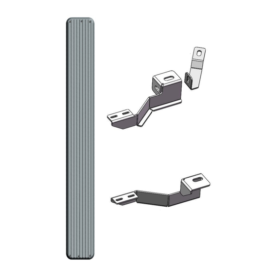
PART LIST
iBoard
by APS
Driver Front Support
Bracket (DFS)
Driver Front Mounting
Bracket (DFM)
Driver Rear Mounting
Bracket (DRM)
Customer Support: info@iboardauto.com
®
Fastener Size
6mm
8mm
10mm
12mm
14mm
Front
Passenger Front Support
Bracket (PFS)
Passenger Front Mount-
ing Bracket (PFM)
Passenger Rear Mount-
ing Bracket (PRM)
1
PART#: IB-019&020A-B
Tightening Torque (ft-lbs)
6-7
16-18
31-32
56-58
92-94
Rev. 20210301
Advertisement
Table of Contents

Subscribe to Our Youtube Channel
Related Manuals for APS iBoard IB-019&020A-B


Summary of Contents for APS iBoard IB-019&020A-B
- Page 1 ® ® iBoard by APS PART#: IB-019&020A-B Fastener Size Tightening Torque (ft-lbs) READ INSTRUCTIONS CAREFULLY BEFORE START ING INSTALLATION. REMOVE CONTENTS FROM BOX AND VERIFY ALL PARTS ARE PRE- 16-18 SENT. ASSISTANCE IS RECOMMENDED. 10mm 31-32 12mm 56-58 *BODY FRAME MOUNT...
- Page 2 iBoard ® M14 Large Flat M12 Large Flat M12 Lock Washer M12 Hex Nut M12X1.75-120mm Hex Bolt M12X1.75-30mm Hex Bolt Washer Washer M6X1 Nylon M6 Large Flat M6X1-20mm Washer Lock Nut Square Head Bolt STEP 1 STEP 3 Start installation from the driver side front of the vehicle. Re- Select Driver Front Support Bracket (DFS) and insert (1) move the factory front body mount bolt from the underside of M12X1.75-120mm Hex Bolt with (1) M12 Large Flat Washer...
- Page 3 iBoard ® STEP 5 (1) M12 Large Flat Washer (1) M12 Lock Washer (1) M12 Hex Nut Move to the rear mounting location. Locate the driver side rear Mounting Bracket, repeat Steps 1 for Driver Rear Mounting Bracket (DRM) installation. Do not fully tighten hardware at this time.
- Page 4 iBoard ® STEP 7 Level and adjust the Running Board and fully tighten all hard- ware. (Fig 7) Installation Completed STEP 8 Attention Do periodic inspections to the installation to make sure that all hardware is secure and tight. Repeat Steps 1-7 for other side Running Board installation. The installation is completed (Fig 7).
Need help?
Do you have a question about the iBoard IB-019&020A-B and is the answer not in the manual?
Questions and answers