Advertisement
Quick Links
®
iBoard
READ INSTRUCTIONS CAREFULLY BEFORE
START ING INSTALLATION. REMOVE CONTENTS
FROM BOX AND VERIFY ALL PARTS ARE PRE-
SENT. ASSISTANCE IS RECOMMENDED.
*ROCKER PANEL MOUNT
*DRILLING IS REQUIRED/ CUTTING IS REQUIRED
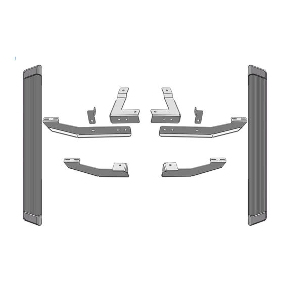
PART LIST
Driver Front Mounting
Driver Front Support
Bracket (DFS)
iBoard
by APS
Bracket (DFM)
Driver Front Bar
Bracket (DFB)
Driver Rear Mounting
Bracket (DRB)
Customer Support: info@iboardauto.com
®
Fastener Size
Tightening Torque (ft-lbs)
6mm
8mm
10mm
12mm
14mm
Front
Passenger Front Mounting
Bracket (PFM)
Passenger Front Support
Passenger Front Bar
Bracket (PFB)
Passenger Rear Mounting
Bracket (PRB)
1
PART#: IB-R192
Required
6-7
√
16-18
√
31-32
√
56-58
X
92-94
X
Bracket (PFS)
Rev. 20220901
Advertisement

Related Manuals for APS iBoard IB-R192


Summary of Contents for APS iBoard IB-R192
- Page 1 ® ® iBoard by APS PART#: IB-R192 Fastener Size Tightening Torque (ft-lbs) Required READ INSTRUCTIONS CAREFULLY BEFORE START ING INSTALLATION. REMOVE CONTENTS √ FROM BOX AND VERIFY ALL PARTS ARE PRE- SENT. ASSISTANCE IS RECOMMENDED. 16-18 √ 10mm 31-32 √...
- Page 2 iBoard ® Hardware Package A (For Bracket Installation) Item Description Item Description M10X35 Long Bolt Plates M10 Hex Nuts M10X35 Short Bolt Plates M8X1.25-35mm Hex Bolts M10X1.5-35mm Hex Bolts M8 Large Flat Washers M10 Large Flat Washers M8 Lock Washers M10 Lock Washers M8X1.25 Hex Nuts 10 #...
- Page 3 iBoard ® STEP 1 Front Driver Side Inner Frame Channel Start installation from the driver side front of the vehicle. Locate the (3) factory holes (1 round and 2 oval holes), (Fig 1). Insert (1) M10X35 Short Bolt Plate into the smaller, (inner), oval hole and feed the threaded end back out through the larger, (outer), oval hole, (Fig 2).
- Page 4 iBoard ® STEP 4 (2) M10X35 Short Bolt Plates (2) M10 Large Flat Washers (2) M10 Lock Washers (2) M10 Hex Nuts Move to driver side rear mounting location. Locate the large oval slot in the floor panel. Insert (1) M10X35 Long Bolt Plate into the slot, (Fig 7).
- Page 5 iBoard ® STEP 5 STEP 6 Line up the Driver Front Support Bracket (DFS) with the back of Once all (2) mounting brackets are installed. Select a Run- the pinch weld, (Fig 11). Push the Support Bracket up as high ning Board.
- Page 6 iBoard ® STEP 8 STEP 9 Level and adjust the Running Board and fully tighten all hard- Re-install the driver side front Mounting Bracket and Support ware. Bracket. Attach the Support Bracket to the pinch weld with (1) Important: Please follow the recommended Tightening Tor- M8X1.25-35mm Hex Bolt, (2) M8 Large Flat Washers, (1) M8 ques shown in the table on page 1.
Need help?
Do you have a question about the iBoard IB-R192 and is the answer not in the manual?
Questions and answers