
Related Manuals for Lanner IIOT-I330


Summary of Contents for Lanner IIOT-I330
- Page 1 IIOT-I330 User Manual Industrial Communication Platforms IIOT-I330 User Manual Preliminary Draft Version: 1.1 Date of Release:2022-12-27...
- Page 2 - assumed to be qualified in the servicing of computer equipment, such as professional system integrators, or service personnel and technicians. The latest version of this document can be found on Lanner’s official website, available either through the product page or through the Lanner Download Center page with a login account and password.
- Page 3 IIOT-I330 User Manual Taiwan Corporate Headquarters China Lanner Electronics Inc. Beijing L&S Lancom Platform Tech. Co., Ltd. 7F, No.173, Sec.2, Datong Rd. Guodong LOFT 9 Layer No. 9 Huinan Road, Xizhi District, New Taipei City 22184, Huilongguan Town, Changping District, Beijing...
- Page 4 IIOT-I330 User Manual This document is copyrighted © 2022 by Lanner Electronics Inc. All rights are reserved. The original manufacturer reserves the right to make improvements to the products described in this manual at any time without notice. No part of this manual may be reproduced, copied, translated or transmitted in any form or by any means without the prior written permission of the original manufacturer.
- Page 5 IIOT-I330 User Manual Follow these guidelines to ensure general safety: Keep the chassis area clear and dust-free during and after installation. Do not wear loose clothing or jewelry that could get caught in the chassis. Fasten your tie or scarf and roll up your sleeves.
- Page 6 IIOT-I330 User Manual Periodically check the resistance value of the antistatic strap, which should be between 1 and 10 megohms (Mohms). L’équipement électrique génère de la chaleur. La température ambiante peut ne pas être adéquate pour refroidir l’équipement à une température de fonctionnement acceptable sans circulation adaptée. Vérifiez que votre site propose une circulation d’air adéquate.
- Page 7 IIOT-I330 User Manual Before turning on the device, ground the grounding cable of the equipment. Proper grounding (grounding) is very important to protect the equipment against the harmful effects of external noise and to reduce the risk of electrocution in the event of a lightning strike. To uninstall the equipment, disconnect the ground wire after turning off the power. A ground wire is required and the part connecting the conductor must be greater than 4 mm2 or 10 AWG.
- Page 8 IIOT-I330 User Manual Key Features ..........................9 Package Content ........................... 9 Ordering Information ........................9 Optional Accessories ........................10 System Specifications ......................... 11 Physical Overview ........................12 Motherboard Information ......................14 Opening the Chassis ........................26 Installing the Wi-Fi Module (Optional) ..................28 Installing the LTE Module (Optional) ..................
- Page 9 IIOT-I330 User Manual Lanner IIoT-I330 robust fanless industrial gateway features quad-core Intel® Atom X7-E3950 or dual-core Celeron N3350, optional 4G LTE mobile connectivity, DDR3L SO-DIMM memory, onboard eMMC, SATA and mSATA sockets, DP display, and a variety of isolated serial COM, DIO, and GbE LAN (RJ45, SFP) configuration options, with wide operating temperature range and multiple DIN Rail mounting options for various industrial IoT application needs.
- Page 10 IIOT-I330 User Manual Model No. Description 2.5” drive bay kit w/ brackets, screws, SATA/Power cable HDD/SSD Kit mSATA kit w/ thermal pad, screws, sink mSATA Kit LTE Module Kit w/ thermal pad, screws, internal antenna cables, external antennas LTE Kit...
- Page 11 IIOT-I330 User Manual SKU A/B: Intel® Atom™ X7-E3950 Processor Options SKU M/N/O/P: Intel® Celeron N3350 Frequency 1.6 GHz / 1.1GHz Processor System Core Number 4 / 2 Chipset BIOS AMI SPI Flash BIOS Technology DDR3L, up to 1600 MT/s Memory Max.
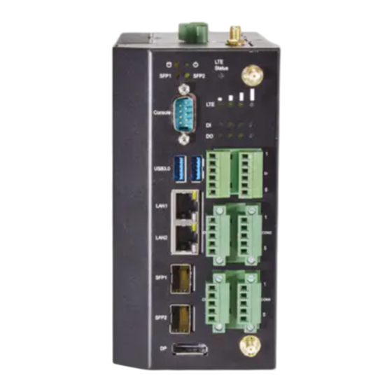
- Page 12 IIOT-I330 User Manual Description Power Input 1x 2-pin Terminal Block for single DC input 9~36V (Typical 12V/24Vdc) Antenna 2x Antennas Reset Button Use a pin to reset the system LED Indicator: Power Status/ Storage Access/ SFP Status/ LTE Status LED Indicators...
- Page 13 IIOT-I330 User Manual 2x5-pin Terminal block for 2x RS232/422/485 (COM1/COM2) Ports RS-232 SOUT COM Port RS-422 RS-485 RS-485 2x5-pin Terminal block for 2x CAN 2.0 A/B Ports (Optional for RS232/422/485 (COM3/COM4) Ports) CAN Port RS-232 SOUT RS-422 RS-485 RS-485 Antenna...
- Page 14 IIOT-I330 User Manual...
- Page 15 IIOT-I330 User Manual The pin headers on the motherboard are often associated with important functions. With the shunt (Jumper) pushed down on the designated pins (the pin numbers are printed on the circuit board, surrounding the pin header), certain feature can be enabled or disable. When changing the jumpers, make sure your system is completely turned off.
- Page 16 IIOT-I330 User Manual 5. SPI1: SPI ROM Connector (For RD Debug) Pin No. Description Pin No. Description HOLD# +1.8V MISO MOSI 6. LPC1: LPC Connector (For RD Debug) Pin No. Description Pin No. Description CLK_24M_P80 L_AD1 PLTRST_P80_N L_AD0 L_FRAME_N P3V3S...
- Page 17 IIOT-I330 User Manual 10. USB1: Dual USB 3.0 Type A Connector Pin No. Description Pin No. Description V5S_USB3_1 V5S_USB3_2 USB2_0- USB2_1- USB2_0+ USB2_1+ USB3_R0- USB3_R1- USB3_R0+ USB3_R1+ USB3_T0- USB3_T1- USB3_T0+ USB3_T1+ 13. RJ1: LAN 1/2 Connector Pin No. Description Pin No.
- Page 18 IIOT-I330 User Manual LAN3_L100_N LAN3_L1000_N P3V3_LAN3 LAN3_ACTLED_N 15. RJ4: LAN 10/100/1000 RJ45 Connector Pin No. Description LAN4_MDI0P LAN4_MDI0N LAN4_MDI1P LAN4_MDI1N P1V5_LAN4 LAN4_MDI2P LAN4_MDI2N LAN4_MDI3P LAN4_MDI3N LAN4_L100_N LAN4_L1000_N P3V3_LAN4 LAN4_ACTLED_N 16. FIBER1: SFP Connector Pin No. Description Pin No. Description SFP3_TX_FAULT...
- Page 19 IIOT-I330 User Manual SFP4_TX_DIS SFP4_RD_P SFP4_I2C_SDA SFP4_I2C_SCL P3V3_SFP4_R SFP4_MOD_ABS P3V3_SFP4_T SFP4_RS0 SFP4_RX_LOS SFP4_TD_P SFP4_RS1 SFP4_TD_N 18. MSATA1: MSATA Connector Pin No. Description Pin No. Description V3P3_S Mechanical Key SATA_RXP0_C V3P3_S SATA_RXN0_C SATA_TXN0_C SATA_TXP0_C V3P3_S V3P3_S V3P3_S...
- Page 20 IIOT-I330 User Manual 19. PSBTN1: External Power Button (2-pin Phoenix Connector) Pin No. Description Pin No. Description EXT_PWRBTN 20. JP10: Board to Board Power Connector Pin No. Description Pin No. Description V12_A V12_A V12_A V12_A V12_A 21. J9: Board to Board Connector Pin No.
- Page 21 IIOT-I330 User Manual 1. JP1: Board to Board Power Connector Pin No. Description Pin No. Description V12_A V12_A V12_A V12_A V12_A 2. PCN1: DC_IN Pin No. Description DC_GND DC_IN (9V~30V) 1. JCN1: CAN BUS1 Termination Load Select Pin No. Description...
- Page 22 IIOT-I330 User Manual COM5_C_TXD_RP COM4_C_TXD_RP COM4_5_GND COM4_5_GND 5. DIO1: DIO Connector Pin No. Description Pin No. Description I_COM DI_0 DO_0 DI_1 DO_1 DI_2 DO_2 DI_3 DO_3 6. M2_1: M.2 NGFF Connector (B-Key) Pin No. Description Pin No. Description V3P3_G1 V3P3_G1...
- Page 23 IIOT-I330 User Manual V3P3_G1 V3P3_G1 V3P3_G1 7. SIM1: SIM Card Socket Pin No. Description Pin No. Description UIM1_PWR UIM1_RST1 UIM1_CLK1 UIM1_DAT1 8. SIM2: SIM Card Socket Pin No. Description Pin No. Description UIM1_PWR UIM1_RST2 UIM1_CLK2 UIM1_DAT2 9. M2_E_KEY1: M.2 NGFF Connector (E-Key) Pin No.
- Page 24 IIOT-I330 User Manual PCIE5_TXP PCIE5_TXN PCIE5_RXP PCIE5_RXN BUF_PCIE5_CLKP BUF_PCIE5_CLKN PERST#EKEY V3P3_S V3P3_S 10. J2: Board to Board Connector Description Description Description Description V3P3_S P1_S0_2 CTS#2 LAN34GND USB2_DP4 RTS#2 USB2_DP3 USB2_DN4 SOUT#2 USB2_DN3 CTS#3 SIN#2 RTS#3 PCIE5_TXP USB3_TX3_P SOUT#3 PCIE5_TXN CTS#4...
- Page 25 IIOT-I330 User Manual PCIE5_RXN SIN#4 USB3_RX3_N RTS#5 SOUT#5 BUF_PCIE5_CLKP SOUT#6 BUF_PCIE4_CLKP SIN#5 BUF_PCIE5_CLKN SIN#6 BUF_PCIE4_CLKN V5_S PLTRST_BUF3_N V3P3_S V3P3_S LATCH_EN_GPH V3P3_S LATCH_DIS_GPL V5_S GPIO_BYPASS_EN V3P3_A SMB_CLK_BUF2 P1_RT_1 SMB_DATA_BUF2 V5_S P1_S0_1 V12_S 11. JP1: Board to Board Power Connector Pin No.
- Page 26 IIOT-I330 User Manual To reduce the risk of personal injury, electric shock, or damage to the system, please remove all power connections to shut down the device completely. Also, please wear ESD protection gloves when conducting the steps in this chapter.
- Page 27 IIOT-I330 User Manual 4. Lift the cover to remove.
- Page 28 IIOT-I330 User Manual The motherboard provides one M.2 E-Key slot for a Wi-Fi module card. Wi-Fi module requires two antennas. Please follow the procedures for installation. 1. Locate the M.2 slot on the motherboard. 2. Align the notch of the module card with the socket key in the pin slot.
- Page 29 IIOT-I330 User Manual Top Panel 1. Locate the two (2) antenna hole placements (A1, A2). Locate the two (2) IPEX connectors on the Wi-Fi module card. 2. Connect the RF cables to the IPEX connectors on the Wi-Fi module card and screw the other end of the cable in the antenna holes.
- Page 30 IIOT-I330 User Manual The system supports one M.2 B-Key for LTE module card expansion. LTE module requires two antennas and one antenna for GPS (depending upon LTE module). Please follow the procedures for installation. 1. Locate the M.2 slot on the motherboard.
- Page 31 IIOT-I330 User Manual Front & Bottom Panel ㄉ ㄉ GPS Antenna 1. Locate the three (3) antenna hole placement (A1, A2, A3). Locate the three (3) IPEX connectors on the LTE module card. 2. Connect the RF cables to the IPEX ㄉ...
- Page 32 IIOT-I330 User Manual 3. Screw on the three antennas to the system. 1. The dual-SIM card slot is located right next to the LTE module card. 2. Insert and push the SIM card, gold contacts facing downwards, all the way in until it clicks into place.
- Page 33 IIOT-I330 User Manual To install an optional mSATA card storage expansion, need to first access the bottom (second layer) section of the internal system. 1. Power off the system and remove the bottom side chassis cover. Top Side Chassis Cover 2.
- Page 34 IIOT-I330 User Manual 4. Remove the five (5) screws on the top motherboard section. 5. Gently lift up the top motherboard section. 6. Locate the mSATA slot on the bottom (second layer) motherboard. 7. Align the notch of the mSATA storage card with the socket key in the pin slot.
- Page 35 IIOT-I330 User Manual 9. Push down on the module card and secure it with two (2) screws. 10. Next, thermal pad placement. Remove the protective film on the thermal pad (included in the accessory pack) and gently place on the module card.
- Page 36 IIOT-I330 User Manual The system supports one 2.5” HDD/SSD slot (SSD preferred) drive bay. The following will discuss disk drive installation procedures. 1. The SSD kit includes: 1x 2.5” SSD 1x SATA Cables 1x SSD Bracket 1x Bracket Holder SSD Bracket Bracket 2.5”...
- Page 37 IIOT-I330 User Manual 5. Place the bracket holder on the bracket and secure with two (2) screws. 6. Place the bracket (with installed SSD) on the chassis cover, secure with four (4) screws. 7. Insert the other end of the SATA data...
- Page 38 IIOT-I330 User Manual The system can be mounted via DIN Rail method with an optional DIN Rail kit. 1. Attach the DIN rail bracket to the rear of the system with three (3) screws. 2. Hang the system onto a rail by engaging the hook of the Bracket into the DIN Rail until it is totally fixed.
- Page 39 IIOT-I330 User Manual To enter the BIOS setup utility, follow the steps below: 1. Boot up the system. 2. Pressing the <Tab> or <Del> key immediately allows you to enter the Setup utility, then you will be directed to the BIOS main screen. The instructions for BIOS navigations are as below:...
- Page 40 IIOT-I330 User Manual Setup main page contains BIOS information and project version information. Item Description BIOS Vendor: American Megatrends Core Version: AMI Kernel version, CRB code base, X64 Compliancy: UEFI version, PI version BIOS Information Project Version: BIOS release version...
- Page 41 IIOT-I330 User Manual Select the Advanced menu item from the BIOS setup screen to enter the “Advanced” setup screen. Users can select any of the items in the left frame of the screen. IIOT-I330A/B/M/N IIOT-I330O/P...
- Page 42 IIOT-I330 User Manual...
- Page 43 IIOT-I330 User Manual Feature Options Description Enables or disables BIOS support for security device. By Security Device Enabled disabling this function, OS will not show Security Device. TCG Support Disabled EFI protocol and INT1A interface will not be available. Enabled SHA-1 PCR Bank Enables or disables SHA-1 PCR Bank.
- Page 44 IIOT-I330 User Manual IIOT-I330A/B/M/N IIOT-I330O/P...
-
Page 45: Serial Port 1 Configuration
IIOT-I330 User Manual Serial Port1 Configuration Feature Options Description Enabled Serial Port Enables or disables Serial Port 1. Disabled Device Settings IO=3F8h; IRQ = 4 COM1 MODE RS232 Select Com Mode as RS232... - Page 46 IIOT-I330 User Manual Serial Port2 Configuration (IIOT-I330A/B/M/N) Feature Options Description Enabled Serial Port Enables or disables Serial Port 2. Disabled Device Settings IO=2F8h; IRQ = 3 RS232 COM2 MODE RS485 Select Com Mode as RS232/RS485/RS422 RS422 Disabled COM2 Termination COM RS-422/485 Receiver Termination...
- Page 47 IIOT-I330 User Manual Serial Port3 Configuration (IIOT-I330A/B/M/N) Feature Options Description Enabled Serial Port Enables or disables Serial Port 3. Disabled Device Settings IO=3E8h; IRQ = 5 RS232 COM3 MODE RS485 Select Com Mode as RS232/RS485/RS422 RS422 Disabled COM3 Termination COM RS-422/485 Receiver Termination...
- Page 48 IIOT-I330 User Manual Serial Port4 Configuration (IIOT-I330A/B/M/N) Feature Options Description Enabled Serial Port Enables or disables Serial Port 4. Disabled Device Settings IO=2E8h; IRQ = 6 RS232 COM4 MODE RS485 Select Com Mode as RS232/RS485/RS422 RS422 Disabled COM4 Termination COM RS-422/485 Receiver Termination...
- Page 49 IIOT-I330 User Manual Serial Port5 Configuration (IIOT-I330A/B/M/N) Feature Options Description Enabled Serial Port Enables or disables Serial Port 2. Disabled Device Settings IO=2F0h; IRQ = 7 RS232 COM5 MODE RS485 Select Com Mode as RS232/RS485/RS422 RS422 Disabled COM5 Termination COM RS-422/485 Receiver Termination...
- Page 50 IIOT-I330 User Manual Item Description CPU Temp This value reports the CPU temperature. SYS Temp This value reports the System temperature. VCORE This value reports the CPU VCORE. This value reports the 12V Input voltage This value reports the 5V Input voltage.
- Page 51 IIOT-I330 User Manual Feature Options Description Enabled Watch Dog Timer Enable or Disable Watch Dog function Disabled...
- Page 52 IIOT-I330 User Manual Feature Options Description Output High Digital I/O Pin 1 Configure Digital I/O Pin High or Low Output Low Output High Digital I/O Pin 2 Configure Digital I/O Pin High or Low Output Low Output High Digital I/O Pin 3...
- Page 53 IIOT-I330 User Manual Feature Options Description Output High DI0 LED Configure DIO LED High or Low Output Low Output High DI1 LED Configure DIO LED High or Low Output Low Output High DI2 LED Configure DIO LED High or Low...
- Page 54 IIOT-I330 User Manual Feature Options Description Output High LTE_Y Configure LTE_Y LED High or Low Output Low Output High LTE_G Configure LTE_G LED High or Low Output Low Output High LTE_R Configure LTE_R LED High or Low Output Low Output High...
- Page 55 IIOT-I330 User Manual Feature Options Description COM0 Enabled Enables or disables Console Redirection Console Redirection Disabled...
-
Page 56: Console Redirection Settings
IIOT-I330 User Manual Console Redirection Settings Feature Options Description ANSI: Extended ASCII char set. VT100 VT100: ASCII char set. VT100+ Terminal Type VT100+: Extends VT100 to support color, function keys, etc. VT-UTF8 VT-UTF8: Uses UTF8 encoding to map Unicode chars onto 1 ANSI or more bytes. - Page 57 IIOT-I330 User Manual VT-UTF8 Combo Disabled Enable VT-UTF8 Combination Key Support for ANSI/VT100 Key Support Enabled terminals Disabled With this mode enabled only text will be sent. This is to Recorder Mode Enabled capture Terminal data. Disabled Resolution 100x31 Enables or disables extended terminal resolution.
- Page 58 IIOT-I330 User Manual Legacy Console Redirection Setting Feature Options Description Redirection Select a COM port to display redirection of Legacy OS and COM0 COM Port Legacy OPROM Messages 80x24 On Legacy OS, the Number of Rows and Columns Resolution 80x25...
- Page 59 IIOT-I330 User Manual Feature Options Description Intel Virtualization Disabled When enabled, a VMM can utilize the additional hardware Technology Enabled capabilities provided by Vanderpool Technology Disabled VT-d Enable/Disable CPU VT-d Enabled When a processor thermal sensor trips (either core), the...
-
Page 60: Socket 0 Cpu Information
IIOT-I330 User Manual Socket 0 CPU Information... -
Page 61: Cpu Power Management
IIOT-I330 User Manual CPU Power Management Feature Options Description Disabled EIST Enable/Disable Intel SpeedStep Enabled... - Page 62 IIOT-I330 User Manual Feature Options Description Globally Enables or Disables 64bit capable Devices to be Disabled Above 4G Decoding Decoded in Above 4G Address Space (Only if System Enabled Supports 64 bit PCI Decoding). Disabled Re-enable Bus Master Attribute disabled during Pci...
- Page 63 IIOT-I330 User Manual Feature Options Description Enables Legacy USB support. Enabled Auto option disables legacy support if no USB devices are Legacy USB Support Disabled connected; Auto Disabled option will keep USB devices available only for EFI applications. Enabled This is a workaround for OSes without XHCI hand-off support.
- Page 64 IIOT-I330 User Manual Feature Options Description Disabled CSM Support Enables or disables CSM Support Enabled Do Not Launch Network UEFI Controls the execution of UEFI and Legacy PXE OpROM Legacy Do Not Launch Controls the execution of UEFI and Legacy Storage...
- Page 65 IIOT-I330 User Manual...
- Page 66 IIOT-I330 User Manual Feature Options Description Disabled Control Legacy PXE LAN1 Control Legacy PXE Boot from which Lan Boot from LAN2...
- Page 67 IIOT-I330 User Manual Select the Chipset menu item from the BIOS setup screen to enter the “Chipset” setup screen. Users can select any of the items in the left frame of the screen.
- Page 68 IIOT-I330 User Manual Feature Options Description 2 GB 2.25 GB Max TOLUD 2.5 GB Maximum Value of TOLUD. 2.75 GB 3 GB Enable/Disable above MemoryMappedIO BIOS Above 4GB MMIO Enabled assignment This is disabled automatically when Aperture Size BIOS assignment...
- Page 69 IIOT-I330 User Manual Feature Options Description Quiet Serial IRQ Mode Configure Serial IRQ Mode. Continuous Windows Android OS Selection Select the target OS Win7 Intel Linux...
- Page 70 IIOT-I330 User Manual...
-
Page 71: Sata Drives
IIOT-I330 User Manual SATA Drives... - Page 72 IIOT-I330 User Manual Feature Options Description Aggressive LPM Enabled Enable PCH to aggressively enter link power state. Support Disabled Enabled Port 0 Enable or Disable SATA Port Disabled SATA Port 0 Enabled If enabled, SATA port will be reported as Hot Plug capable.
-
Page 73: Usb Configuration
IIOT-I330 User Manual USB Configuration Feature Options Description Once disabled, XHCI controller would be function disabled, none of Enable xHCI Mode the USB devices are detectable and usable during boot and in OS. Do Disable not disable it unless for debug purpose. -
Page 74: Miscellaneous Configuration
IIOT-I330 User Manual Miscellaneous Configuration Feature Options Description Specify what state to go to when power is re-applied after a power Power On Restore AC failure (G3 state). S0 State: System will boot directly as soon as power Power Off Power Loss applied.S5 State: System keeps in power-off state until power button... - Page 75 IIOT-I330 User Manual Select the Security menu item from the BIOS setup screen to enter the Security Setup screen. Users can select any of the items in the left frame of the screen. Feature Description If ONLY the Administrator's password is set, it only limits access to Administrator Password Setup and is only asked for when entering Setup.
-
Page 76: Secure Boot
IIOT-I330 User Manual Secure Boot Feature Options Description Disabled Secure Boot is activated when Platform Key (PK) is enrolled, System Secure Boot Enabled mode is User/Deployed, and CSM function is disabled. Secure Boot Mode - Custom & Standard, Set UEFI Secure Boot Mode... -
Page 77: Key Management
IIOT-I330 User Manual Key Management Feature Options Description Factory keys Disabled Allow to provision factory default Secure Boot keys when System is Provision Enabled in Setup Mode Restore None Force System to User Mode - install all Factory Default keys Factory keys Allows the image to run in Secure Boot mode. - Page 78 IIOT-I330 User Manual Select the Boot menu item from the BIOS setup screen to enter the Boot Setup screen. Users can select any of the items in the left frame of the screen. Feature Options Description The number of seconds to wait for setup activation key.
- Page 79 IIOT-I330 User Manual Select the Save and Exit menu item from the BIOS setup screen to enter the Save and Exit Setup screen. Users can select any of the items in the left frame of the screen. ■ Discard Changes and Exit Select this option to quit Setup without saving any modifications to the system configuration.
- Page 80 IIOT-I330 User Manual ■ Restore Defaults Restore default values for all setup options. Select “Yes” to load Optimized defaults. Note The items listed under Boot Override will depend on the devices connected to this system.
- Page 81 IIOT-I330 User Manual 1. All products are under warranty against defects in materials and workmanship for one year from the date of purchase. 2. The buyer will bear the return freight charges for goods returned for repair within the warranty period;...
- Page 82 IIOT-I330 User Manual When requesting RMA service, please fill out the following form. Without this form enclosed, your RMA cannot be processed.
Need help?
Do you have a question about the IIOT-I330 and is the answer not in the manual?
Questions and answers