
Related Manuals for Lanner ICS-I372


Summary of Contents for Lanner ICS-I372
- Page 1 ICS-I372 User Manual Industrial Communication Platforms ICS-I372 User Manual Version: 1.0 Date of Release:2023-10-31...
- Page 2 - assumed to be qualified in the servicing of computer equipment, such as professional system integrators, or service personnel and technicians. The latest version of this document can be found on Lanner’s official website, available either through the product page or through the Lanner Download Center page with a login account and password.
- Page 3 ICS-I372 User Manual Contact Information Taiwan Corporate Headquarters China Lanner Electronics Inc. Beijing L&S Lancom Platform Tech. Co., Ltd. 7F, No.173, Sec.2, Datong Rd. Guodong LOFT 9 Layer No. 9 Huinan Road, Xizhi District, New Taipei City 22184, Huilongguan Town, Changping District, Beijing...
- Page 4 Copyright and Trademarks This document is copyrighted © 2023 by Lanner Electronics Inc. All rights are reserved. The original manufacturer reserves the right to make improvements to the products described in this manual at any time without notice. No part of this manual may be reproduced, copied, translated or transmitted in any form or by any means without the prior written permission of the original manufacturer.
- Page 5 ICS-I372 User Manual Safety Guidelines Follow these guidelines to ensure general safety: Keep the chassis area clear and dust-free during and after installation. Do not wear loose clothing or jewelry that could get caught in the chassis. Fasten your tie or scarf and roll up your sleeves.
- Page 6 ICS-I372 User Manual Sé curité de fonctionnement L’équipement électrique génère de la chaleur. La température ambiante peut ne pas être adéquate pour refroidir l’équipement à une température de fonctionnement acceptable sans circulation adaptée. Vérifiez que votre site propose une circulation d’air adéquate.
- Page 7 ICS-I372 User Manual Electrical Safety Instructions Before turning on the device, ground the grounding cable of the equipment. Proper grounding (grounding) is very important to protect the equipment against the harmful effects of external noise and to reduce the risk of electrocution in the event of a lightning strike.
-
Page 8: Table Of Contents
ICS-I372 User Manual Table of Contents Chapter 1: Product Overview ............9 Key Features ..........................9 Package Content ........................... 9 Ordering Information ........................9 System Specifications ......................... 10 Physical Overview ........................11 Motherboard Information ......................13 Chapter 2: Hardware Installation............ 26 Opening the Bottom Chassis ...................... -
Page 9: Chapter 1: Product Overview
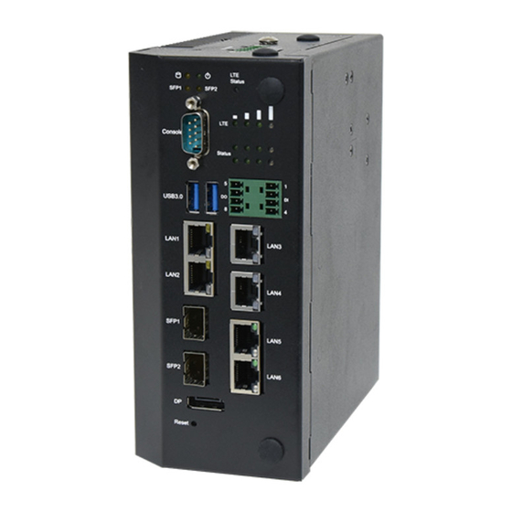
CHAPTER 1: PRODUCT OVERVIEW The ICS-I372 series is a DIN-mount platform featuring an Intel® Elkhart Lake Embedded SKU, equipped with either a 2-core or 4-core CPU and boasting 8x 2.5G RJ45, 6x 2.5G RJ45 plus 2x SFP, or even 4x 2.5GbE RJ45 plus 2x SFP ports with one or two pairs of Bypass functionality. -
Page 10: System Specifications
ICS-I372 User Manual System Specifications SKU A/B/C/D: Intel® Atom® X6425E (Elkhart Lake) Processor Options SKU E/F: Intel® Atom® X6413E (Elkhart Lake) Frequency 2.0GHz / 1.5GHz Processor System Core Number 4 Cores Chipset Intel® i226-IT BIOS AMI SPI Flash BIOS Technology... -
Page 11: Physical Overview
ICS-I372 User Manual Physical Overview Front & Rear Panel Description LED Indicator: Storage Access/Power Status/SFP Status/LTE Status LED Indicators 4x LTE Signal Level Status 2x4 Programmable Console Port 1x DB9 Console Port USB Port 2x USB 3.0 Type A Ports SKU A/B: 8x GbE RJ45 (1 or 2 pair bypass) Ports SKU C/D: 6x GbE RJ45;... - Page 12 ICS-I372 User Manual Top Panel Description Power Input 1x 6-pin Terminal Block for Dual DC Input 12~36V Antenna 2x Antenna Holes Bottom Panel...
-
Page 13: Motherboard Information
ICS-I372 User Manual Motherboard Information Block Diagram... - Page 14 ICS-I372 User Manual Internal Jumpers and Connector The pin headers on the motherboard are often associated with important functions. With the shunt (Jumper) pushed down on the designated pins (the pin numbers are printed on the circuit board, surrounding the pin header), certain feature can be enabled or disable.
- Page 15 ICS-I372 User Manual 5. SPI1: SPI ROM Connector (For RD Debug) Pin No. Description Pin No. Description SPI0_IO3_HOLD# SPI0_CS0_R# V3P3A_1P8A_SPI SPI0_IO1_MISO_R SPI0_CLK_R SPI0_IO0_MOSI_R 6. ESPI1: ESPI Connector (For RD Debug) Pin No. Description Pin No. Description ESPI_CLK ESPI_IO1 ESPI_RST# ESPI_IO0...
- Page 16 ICS-I372 User Manual 10. USB1: Dual USB 3.0 Type A Connector Pin No. Description Pin No. Description V5S_USB3_1 V5S_USB3_2 USB2_0- USB2_1- USB2_0+ USB2_1+ USB3_R0- USB3_R1- USB3_R0+ USB3_R1+ USB3_T0- USB3_T1- USB3_T0+ USB3_T1+ 13. RJ1: LAN 1/2 Connector Pin No. Description Pin No.
- Page 17 ICS-I372 User Manual LAN3_MDI3N LAN3_L100_N LAN3_L1000_N P3V3_LAN3 LAN3_ACTLED_N 15. RJ3: LAN 10/100/1000 RJ45 Connector Pin No. Description LAN4_MDI0P LAN4_MDI0N LAN4_MDI1P LAN4_MDI1N P1V5_LAN4 P1V5_LAN4 LAN4_MDI2P LAN4_MDI2N LAN4_MDI3P LAN4_MDI3N LAN4_L100_N LAN4_L1000_N P3V3_LAN4 LAN4_ACTLED_N 16. FIBER1: SFP Connector Pin No. Description Pin No.
- Page 18 ICS-I372 User Manual 17. FIBER2: SFP Connector Pin No. Description Pin No. Description SFP4_TX_FAULT SFP4_RD_N SFP4_TX_DIS SFP4_RD_P SFP4_I2C_SDA SFP4_I2C_SCL P3V3_SFP4_R SFP4_MOD_ABS P3V3_SFP4_T SFP4_RS0 SFP4_RX_LOS SFP4_TD_P SFP4_RS1 SFP4_TD_N 18. M2_M_KEY1: M.2 M-Key SATA Connector Pin No. Description Pin No. Description +P3V3_S...
- Page 19 ICS-I372 User Manual SATA_C_TXP0 Mechanical Key M2_PEDET +P3V3_S +P3V3_S +P3V3_S 19. JP10: Board to Board Power Connector Pin No. Description Pin No. Description V12_A V12_A V12_A V12_A V12_A 20. J11: Board to Board Connector Description Description Description Description +P3V3_S P1_S0_2...
- Page 20 ICS-I372 User Manual LATCH_DIS_GPL +P5V_S GPIO_BYPASS_EN +P3V3_A SMB_CLK_BUF2 P1_RT_1 SMB_DATA_BUF2 +P5V_S P1_S0_1 +P12V_S I/O Board 1. RJ2: RJ45 Jack with LED Pin No. Description LAN1_MDI0P LAN1_MDI0N LAN1_MDI1P LAN1_MDI1N TCL1 TCL2 LAN1_MDI2P LAN1_MDI2N LAN1_MDI3P LAN1_MDI3N LAN1_LINK_2500_N LAN1_LINK_1000_N LAN1_LINK_ACT_N P3V3_LAN1 2. RJ3: RJ45 Jack with LED Pin No.
- Page 21 ICS-I372 User Manual LAN2_LINK_2500_N LAN2_LINK_1000_N LAN2_LINK_ACT_N P3V3_LAN2 3. RJ1: LAN 1/2 Connector, RJ45 Jack with LED Pin No. Description Pin No. Description P3_MDXP0 P4_MDXP0 P3_MDXN0 P4_MDXN0 P3_MDXP1 P4_MDXP1 P3_MDXP2 P4_MDXP2 P3_MDXN2 P4_MDXN2 P3_MDXN1 P4_MDXN1 P3_MDXP3 P4_MDXP3 P3_MDXN3 P4_MDXN3 V3P3_S V3P3_S...
- Page 22 ICS-I372 User Manual M2_USB3_RXN UIM1_RST M2_USB3_RXP UIM1_CLK UIM1_DAT M2_USB3_TXN UIM1_PWR M2_USB3_TXP V3P3_G1 V3P3_G1 V3P3_G1 6. SIM1: SIM Card Socket Pin No. Description Pin No. Description UIM1_PWR1 UIM1_RST1 UIM1_CLK1 UIM1_DAT1...
- Page 23 ICS-I372 User Manual 7. SIM2: SIM Card Socket Pin No. Description Pin No. Description UIM1_PWR2 UIM1_RST2 UIM1_CLK2 UIM1_DAT2 8. M2_E_KEY1: M.2 NGFF Connector (E-Key) Pin No. Description Pin No. Description V3P3_S USB2_DP4 V3P3_S USB2_DN4 LED_WLAN1- LED_WLAN2- SW_C_PCIE_TX_P5 SW_C_PCIE_TX_N5 SW_C_PCIE_TX_N5 SW_C_PCIE_RX_N5...
- Page 24 ICS-I372 User Manual V3P3_S V3P3_S 9. J2: Board to Board Connector Description Description Description Description V3P3_S P1_S0_2 CTS#2 LAN34GND USB2_DP4 RTS#2 USB2_DP3 USB2_DN4 SOUT#2 USB2_DN3 CTS#3 SIN#2 RTS#3 PCIE5_TXP USB3_TX3_P SOUT#3 PCIE5_TXN CTS#4 USB3_TX3_N SIN#3 RTS#4 PCIE5_RXP SOUT#4 USB3_RX3_P CTS#5...
- Page 25 ICS-I372 User Manual 10. JP1: Board to Board Power Connector Pin No. Description Pin No. Description V12_A V12_A V12_A V12_A V12_A 11. PCN1: DCIN Terminal Block Pin No. Description DC_PWR2 (9V~36V) DC_GND ALARM2 ALARM1 DC_PWR1 (9V~36V) DC_GND...
-
Page 26: Chapter 2: Hardware Installation
ICS-I372 User Manual CHAPTER 2: HARDWARE INSTALLATION To reduce the risk of personal injury, electric shock, or damage to the system, please remove all power connections to shut down the device completely. Also, please wear ESD protection gloves when conducting the steps in this chapter. - Page 27 ICS-I372 User Manual 4. Lift the bottom cover chassis to remove.
-
Page 28: Opening The Top Chassis
ICS-I372 User Manual Opening the Top Chassis To install the system memory and optional mSATA storage card expansion, we need to access the bottom (second layer) section of the system. 1. Power off the system and remove the bottom chassis cover. - Page 29 ICS-I372 User Manual 4. Gently remove the top chassis cover from the motherboard layers. 5. Remove the six (6) screws on the top motherboard section. 6. Gently lift up the top motherboard section.
-
Page 30: Installing The System Memory
ICS-I372 User Manual Installing the System Memory The system supports one system memory slot, please follow the steps for installation. 1. Power off the system, and open the top and bottom chassis cover, and remove the top motherboard layer. Locate a metal partition covering the DIMM socket placement. - Page 31 ICS-I372 User Manual 6. Then place the metal partition over the DIMM module, and secure with two (2) screws. 8. Gently place the top motherboard section back on top and secure with the original six (6) screws. Then, enclose the top chassis cover with the motherboard section, secure with the original seven (7) screws.
-
Page 32: Installing The Msata Storage (Optional)
ICS-I372 User Manual Installing the mSATA Storage (Optional) The system supports one mSATA slot. Follow the procedures below for installing a mSATA storage module card. 1. Power off the system, and open the top and bottom chassis cover, and remove the top motherboard layer. - Page 33 ICS-I372 User Manual 6. Then place the metal partition over the storage module, and secure with two (2) screws. 7. Gently place the top motherboard section back on top and secure with the original six (6) screws. Then, enclose the top chassis cover with the motherboard section, secure with the original seven (7) screws.
-
Page 34: Installing The Wi-Fi Module (Optional)
ICS-I372 User Manual Installing the Wi-Fi Module (Optional) The motherboard provides one M.2 E-Key slot for a Wi-Fi module card. Wi-Fi module requires two antennas. Please follow the procedures for installation. 1. Power off the system and remove the bottom chassis cover. Locate the M.2 slot on the (top) motherboard. - Page 35 ICS-I372 User Manual Installing Wi-Fi Antenna Bottom Panel 1. Locate the two (2) antenna hole placements (A1, A2). Locate the two (2) IPEX connectors on the Wi-Fi module card. 2. Connect the RF cables to the IPEX connectors on the Wi-Fi module card and screw the other end of the cable in the antenna holes.
-
Page 36: Installing The Lte/5G Module (Optional)
ICS-I372 User Manual Installing the LTE/5G Module (Optional) The system supports one M.2 B-Key for LTE/5G module card expansion. If a 5G module is installed, there will be no more room for 2.5” SSD expansion. LTE module requires two antennas. 5G module requires four antennas. - Page 37 ICS-I372 User Manual Installing 5G Antenna Front Panel Top Panel ㄉ ㄉ ㄉ 1. Locate the four (4) antenna hole placement (A1, A2, A3, A4). Locate the four (4) IPEX connectors on the 5G module card. 2. Connect the RF cables to the IPEX...
- Page 38 ICS-I372 User Manual ㄉ ㄉ 3. Then, screw on the four antennas to the system.
- Page 39 ICS-I372 User Manual Installing SIM Cards 1. The dual-SIM card slot is located right next to the LTE/5G module card. 2. Insert and push the SIM card, gold contacts facing downwards, all the way in until it clicks into place. Repeat if dual SIM cards will be placed.
-
Page 40: Din Rail Mounting (Optional)
ICS-I372 User Manual DIN Rail Mounting (Optional) The system can be mounted via DIN Rail method with an optional DIN Rail kit. 1. Attach the DIN rail bracket to the rear of the system with three (3) screws. 2. Hang the system onto a rail by engaging the hook of the Bracket into the DIN Rail until it is totally fixed. -
Page 41: Chapter 3: Software Setup
ICS-I372 User Manual CHAPTER 3: SOFTWARE SETUP BIOS Setup BIOS (Basic Input / Output System) is the program that controls the computer boot process. The purpose of the BIOS is to identify and initialize processor, memory, hard drives, optical drives, and other hardware. The system has AMI BIOS built-in, with a setup utility that allows users to configure required settings or to activate certain system features. -
Page 42: Main Page
ICS-I372 User Manual Main Page Setup main page contains BIOS information and project version information. Feature Description BIOS Vendor: American Megatrends Core Version: AMI Kernel version, CRB code base, X64 Compliancy: UEFI version, PI version BIOS Information Project Version: BIOS release version... -
Page 43: Advanced Page
ICS-I372 User Manual Advanced Page Select the Advanced menu item from the BIOS setup screen to enter the “Advanced” setup screen. Users can select any of the items in the left frame of the screen. - Page 44 ICS-I372 User Manual CPU Configuration Feature Options Description Disabled Hardware Prefetcher To turn on/off the MLC streamer prefetcher. Enabled Intel (VMX) Disabled When enabled, a VMM can utilize the additional hardware Virtualization Enabled capabilities provided by Vanderpool Technology. Technology Disabled...
- Page 45 ICS-I372 User Manual Power & Performance Feature Options Description Max Battery Boot performance Max Non-Turbo Select the performance state that the BIOS will set mode Performance starting from reset vector. Turbo Performance Intel(R) Disabled Allows more than two frequency ranges to be...
- Page 46 ICS-I372 User Manual PCH-FW Configuration Feature Options Description Me FW Image Disabled Enable/Disable ME FW Image Re-Flash function. Re-Flash Enabled...
- Page 47 ICS-I372 User Manual Trusted Computing Feature Options Description Enables or disables BIOS support for security device. By Security Device Enabled disabling this function, OS will not show Security Device. TCG Support Disabled EFI protocol and INT1A interface will not be available.
- Page 48 ICS-I372 User Manual Physical Presence Spec Select to tell OS to support PPI Spec Version 1.2 or 1.3. Version NOTE: Some HCK tests might not support 1.3. TPM 20 InterfaceType Select TPM 20 Device for the Communication Interface. TPM 1.2 will restrict support to TPM 1.2 devices; while TPM TPM 1.2...
- Page 49 ICS-I372 User Manual F81966 Super IO Configuration...
- Page 50 ICS-I372 User Manual Serial Port 1 Configuration Feature Options Description Enabled Serial Port Enables or disables Serial Port (COM) Disabled...
- Page 51 ICS-I372 User Manual Serial Port 2 Configuration Feature Options Description Enabled Serial Port Enables or disables Serial Port (COM) Disabled...
- Page 52 ICS-I372 User Manual Serial Port 3 Configuration Feature Options Description Enabled Serial Port Enables or disables Serial Port (COM) Disabled...
- Page 53 ICS-I372 User Manual Serial Port 4 Configuration Feature Options Description Enabled Serial Port Enables or disables Serial Port (COM) Disabled...
- Page 54 ICS-I372 User Manual Serial Port 5 Configuration Feature Options Description Enabled Serial Port Enables or disables Serial Port (COM) Disabled...
- Page 55 ICS-I372 User Manual Serial Port 6 Configuration Feature Options Description Enabled Serial Port Enables or disables Serial Port (COM) Disabled...
- Page 56 ICS-I372 User Manual Hardware Monitor...
- Page 57 ICS-I372 User Manual Digital I/O Configuration Feature Options Description Output High Digital I/O Pin 1 Configure Digital I/O Pin 1. Output Low Output High Digital I/O Pin 2 Configure Digital I/O Pin 2. Output Low Output High DI_DRY_EN Configure DI_DRY_EN.
- Page 58 ICS-I372 User Manual Digital I/O LED Configuration Feature Options Description Output High DI0 LED Configure DI0 LED. Output Low Output High DI1 LED Configure DI1 LED. Output Low Output High DI2 LED Configure DI2 LED. Output Low Output High DI3 LED Configure DI3 LED.
- Page 59 ICS-I372 User Manual Digital I/O LTE LED Configuration Feature Options Description Output High LTE_Y Configure LTE_Y LED. Output Low Output High LTE_G Configure LTE_G LED. Output Low Output High LTE_R Configure LTE_R LED. Output Low Output High LTE_B1 Configure LTE_B1 LED.
- Page 60 ICS-I372 User Manual Control Network Stack Boot Feature Options Description Disabled Control Network Stack LAN3 Control Network Stack Boot from which Lan Boot from LAN4...
- Page 61 ICS-I372 User Manual Serial Port Console Redirection Feature Options Description Disabled Console Redirection Console Redirection Enable or Disable. Enabled...
- Page 62 ICS-I372 User Manual Console Redirection Settings Feature Options Description Emulation: VT100 VT100: ASCII char set VT100+ VT100+:Extends VT100 to support color, function keys, etc. Terminal Type VT-UTF8 VT-UTF8:Uses UTF8 encoding to map Unicode chars onto 1 or more bytes ANSI...
- Page 63 ICS-I372 User Manual Disabled With this mode enabled only text will be sent. This is to Recorder Mode Enabled capture Terminal data. Disabled Resolution 100x31 Enables or disables extended terminal resolution. Enabled VT100 LINUX XTERM86 Putty KeyPad Selects FunctionKey and KeyPad on Putty.
- Page 64 ICS-I372 User Manual PCI Subsystem Settings Feature Options Description Disabled If the system has SR-IOV capable PCIe Devices, this option SR-IOV Support Enabled Enables or Disables Single Root IO Virtualization Support.
- Page 65 ICS-I372 User Manual USB Configuration Feature Options Description Enables Legacy USB support. Enabled Auto option disables legacy support if no USB devices are Legacy USB Support Disabled connected. Auto Disabled option will keep USB devices available only for EFI applications.
- Page 66 ICS-I372 User Manual Network Stack Configuration Feature Options Description Disabled Network Stack select Select UEFI Network Stack Enable Disabled Enable/Disable IPv4 PXE boot support. If disabled, IPv4 PXE boot IPv4 PXE Support Enable support will not be available. Disabled Enable/Disable IPv4 HTTP boot support. If disabled, IPv4 HTTP...
- Page 67 ICS-I372 User Manual SDIO Configuration Feature Options Description Auto Auto Option: Access SD device in DMA mode if controller ADMA supports it, otherwise in PIO mode. DMA Option: Access SDIO Access Mode SDMA SD device in DMA mode. PIO Option: Access SD device in PIO mode.
-
Page 68: Chipset
ICS-I372 User Manual Chipset Select the Chipset menu item from the BIOS setup screen to enter the “Chipset” setup screen. Users can select any of the items in the left frame of the screen. - Page 69 ICS-I372 User Manual System Agent (SA) Configuration Feature Options Description Disabled VT-d VT-d capability. Enabled Enabled X2APIC Opt Out Enable/Disable X2APIC_OPT_OUT bit. Disabled...
- Page 70 ICS-I372 User Manual PCH-IO Configuration...
- Page 71 ICS-I372 User Manual SATA Configuration Feature Options Description Enabled SATA Controller(s) Enable/Disable SATA Device. Disabled SATA Mode Selection AHCI Determines how SATA controller(s) operate.
- Page 72 ICS-I372 User Manual SCS Configuration Feature Options Description Enabled eMMC 5.1 Controller Enable or Disable SCS eMMC 5.1 Controller Disabled eMMC 5.1 HS400 Enabled Enable or Disable SCS eMMC 5.1 HS400 Mode Mode Disabled Enable HS400 software Enabled Software tuning should improve eMMC HS400 stability at the...
-
Page 73: Security
ICS-I372 User Manual Security Select the Security menu item from the BIOS setup screen to enter the Security Setup screen. Users can select any of the items in the left frame of the screen. Feature Description If ONLY the Administrator's password is set, then this only limits Administrator Password access to Setup and is only asked for when entering Setup. - Page 74 ICS-I372 User Manual Secure Boot Feature Options Description Secure Boot feature is Activated if Secure Boot is Enabled, Platform Disabled Secure Boot Key (PK) is enrolled and the System is User mode. The mode change Enabled requires platform reset. Secure Boot mode options: Standard or Custom...
- Page 75 ICS-I372 User Manual Key Management Feature Options Description Factory Key Disabled Install factory default Secure Boot keys after the platform reset and Provision Enabled while the System is in Setup mode. Restore Factory Force System to User Mode. Install factory default Secure Boot key...
-
Page 76: Boot Menu
ICS-I372 User Manual Boot Menu Select the Boot menu item from the BIOS setup screen to enter the Boot Setup screen. Users can select any of the items in the left frame of the screen. Feature Options Description Number of seconds to wait for setup activation key. -
Page 77: Save And Exit Menu
ICS-I372 User Manual Save and Exit Menu Select the Save and Exit menu item from the BIOS setup screen to enter the Save and Exit Setup screen. Users can select any of the items in the left frame of the screen. - Page 78 ICS-I372 User Manual ■ Restore Defaults Restore default values for all setup options. Select “Yes” to load Optimized defaults. Note The items listed under Boot Override will depend on the devices connected to this system.
-
Page 79: Appendix A: Terms And Conditions
ICS-I372 User Manual APPENDIX A: TERMS AND CONDITIONS Warranty Policy 1. All products are under warranty against defects in materials and workmanship for one year from the date of purchase. 2. The buyer will bear the return freight charges for goods returned for repair within the warranty period;... - Page 80 ICS-I372 User Manual RMA Service Request Form When requesting RMA service, please fill out the following form. Without this form enclosed, your RMA cannot be processed.
Need help?
Do you have a question about the ICS-I372 and is the answer not in the manual?
Questions and answers