
Related Manuals for Lanner HCP-72i1


Summary of Contents for Lanner HCP-72i1
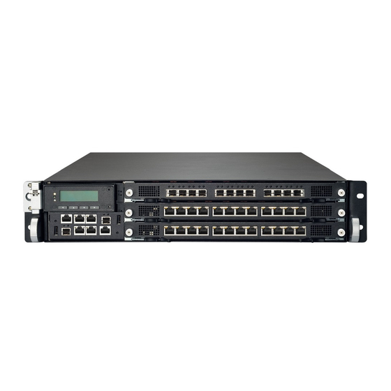
- Page 1 Network Application Platforms Hardware platforms for next generation networking infrastructure HCP-72i1 V1.0 User's Manual Release Date: 2015/06/19 www.lannerinc.com...
-
Page 2: Safety Guidelines
Resource Website installed and used in accordance with the instruction manual, may cause harmful interference to radio Lanner http://www.lannerinc.com communications. Operation of this equipment in a residential area is likely to cause harmful interference Product http://www.lannerinc.com/download-... - Page 3 LITHIUM BATTERY CAUTION: • Coupez complètement l’alimentation en éteignant l’alimentation et en débranchant le cordon Risk of Explosion if Battery is replaced by an incorrect d’alimentation avant d’installer ou de retirer un type. Dispose of used batteries according to the châssis ou de travailler à...
-
Page 4: Revision History
Consignes de sécurité électrique partie métallique du châssis. Vérifiez régulièrement la valeur de résistance du bracelet • Avant d’allumer l’appareil, reliez le câble de mise à la antistatique, qui doit être comprise entre 1 et 10 terre de l’équipement à la terre. mégohms (Mohms). -
Page 5: Table Of Contents
Chapter 2: System Components Mechanical Drawings Front Components Rear Components Chapter 3: Motherboard Information An Internal Glance of HCP-72i1 Jumper and Connector Location Connectors and Jumpers List Jumper Settings & Connectors Pin Definitions Chapter 4: Hardware Installation Preparing the Hardware Installation... - Page 6 Replacing Cooling Fans Rack Mounting Chapter 5: BIOS Setup Main Advanced WHEA Configuration CPU Configuration SATA Configuration USB Configuration Hardware Monitor LAN Module Hardware Monitor LAN Boot Select Serial Port Console Redirection COM Console Redirection Settings Chipset IOH Configuration Intel (R) VT for Directed I/O Configuration Boot Security Save &...
- Page 7 Maintenance Firmware Update Restore Factory Defaults System Administrator Chapter 7: About the PCIe-Switch Feature of HCP-72i1 Brief Default Settings of PCI Express Switch Demonstrating the Switching Methods for the PCIe Switch Initializing the System for Re-planning the Arrangement of PCI Bus ID...
- Page 8 Appendix 1: About the Non-Transparent Bridge Appendix 2: Programming Watchdog Timer Appendix 3: Setting up Console Redirections Appendix 4: Programming the LCM Appendix 5: On Linux Appendix 6: Terms and Conditions Warranty Policy RMA Service www.lannerinc.com...
- Page 9 Chapter 1 Introduction www.lannerinc.com...
-
Page 10: Chapter 1: Introduction
Up to 32GB DDR3 1600 ECC Regis- Memory processors on LGA2011. Max. Capacity tered DIMM HCP-72i1 can be fitted, via the three (max.) swappable Socket 16 x 240-pin DIMM Sockets Supports 32-bit/64-bit I/O blades, with up to 36 1GbE network ports or 24... -
Page 11: Package Contents
Package Contents Your package contains the following items: • HCP-72i1 Network Security Platform • 4 passive CPU heatsink • 2 power cords • 2 SATA cables • 1 crossover Ethernet cable (1.8 meters) • 1 straight-through Ethernet cable (1.8 meters) •... -
Page 12: Block Diagram
Block Diagram PCIe x 8 Molex LAN Module Intel Xeon Memory Bottom (Slot2) PCIe x 8 CPU1 DDR3 x 8 Conn PCIe x 8 LAN Module PCIEC1 Top (Slot0) Intel Xeon PCIe x 8 (NTB) Memory CPU0 Molex Intel Xeon DDR3 x 8 PCIe x 8 (Another MB) -
Page 13: Physical Architecture Of Lanner's Hybridtca
Physical Architecture of Lanner’s HybridTCA The diagram presents all necessary components of Lanner’s Hybrid TCA architecture applied for HCP-72i1. www.lannerinc.com... - Page 14 Chapter 2 System Components www.lannerinc.com...
-
Page 15: Chapter 2: System Components
Chapter 2: System Components Mechanical Drawings Unit: mm www.lannerinc.com... -
Page 16: Front Components
Front Components Component Description RJ-45 console port for connecting to a computer terminal F1 Console for local, out-of-band diagnostic or configuration purpose. • 128 x 64 Graph LCM with 4 key pad F2 LCM • Hinge LCM • 1 LED for power, 1 LED for Status and 1 LED for HDD F3 USB 2.0 Ports USB 2.0 type A connectors. -
Page 17: Rear Components
Rear Components Component Description R1 Cooling fans 5x cooling fans each layer R2 Power supply Redundent power supply for each layer R3 Power Switch Turn on/off of the system www.lannerinc.com... - Page 18 Chapter 3 Motherboard Information www.lannerinc.com...
-
Page 19: Chapter 3: Motherboard Information
Chapter 3: Motherboard Information An Internal Glance of HCP-72i1 The inside of HCP-72i1 is designed based on Lanner’s exclusive HybridTCA structure. This hybrid design integrates two identical, high-performance motherboards for optimal system boost. Upper Board Bottom Board www.lannerinc.com... - Page 20 An Internal Glance of HCP-72i1 HCP-72i1 can be connected with up to 3 LAN modules for networking applications. The image below shows the LAN module “TCM-IXT801A”. PCIe Hot-Swap Power PCIe SFP+ 10G ports www.lannerinc.com...
-
Page 21: Jumper And Connector Location
Jumper and Connector Location The illustration below presents the jumper and connector location of each board. www.lannerinc.com... -
Page 22: Connectors And Jumpers List
Connectors and Jumpers List The tables below list the jumper and connector label of each board. Labels Function FAN1~5 FAN connectors Front Panel Reset Button Setting CONN2 Power-On Button Pin Header CPLD Flash Pin Header MPCIE1 Mini PCIe Socket USBA1 USB connector JSDO23 Security Override... -
Page 23: Jumper Settings & Connectors Pin Definitions
Jumper Settings & Connectors Pin Definitions Front Panel Reset Button Setting(J14) FAN connectors (FAN1~5): The jumper setting for selecting hardware reset or software reset. Software reset is the default option. Five-pin FAN connectors FAN1 Description Description Hardware reset HM_PWMOUT1 Software reset (default) FAN_TECH_IN_FAN1 FAN_TECH_IN_FAN2 Power-On Button (CONN2) - Page 24 Mini-PCIe socket (MPCIE1): USB connector (USBA1) Serves as mSATA storage socket USBA1 Description Description USB2- USB3- Description Description USB2+ USB3+ 3.3V USB23GND USB23GND USB23GND USB23GND Security Override (JSDO23) FLASH DESCRIPTOR SECURITY OVERRIDE WHEN HIGH PCIe Clock_N PCIe Clock_P (Default Not Connect) Mechanical key Port 80 (J13): This is the Port 80h, which is used as 3.3V...
- Page 25 SATA (J23): used to connect SATA disk drive Hot swap LED(CONN3) Description CONN3 Description LED_P LED_N Hot swap MRL(Manual Retention Latch) pin header(CONN1) SATA Re-Driver value flash (J26) SATA signal redriver and conditioner CONN1 Description Description Power Enable# PCIE_R_SDA2 3.3V PCIE_R_SCL2 MOSI2 REST_MCU2#...
- Page 26 Chapter 4 Hardware Installation www.lannerinc.com...
-
Page 27: Chapter 4: Hardware Installation
6. Pull the top blade out while holding the lock-handles. Accessing the Components 1. Due to the hybrid architecture of HCP-72i1, you may access the Upper Board or the Bottom Board. First, locate the rear lock-handles and lock-screws. There should be 2 pairs on each side: two for the Upper Board and the other two for the Bottom Board. -
Page 28: Installing Cpu And The Heat Sink
Installing CPU and the Heat Sink 5. Align the CPU and the notch on the socket. The CPU should fit perfectly into the socket. Note that the CPU fits in the Follow the procedures below for installing a CPU socket in only one direction. 1. -
Page 29: Installing The System Memory
Installing IPMI Card on OPMA Socket Installing the System Memory The motherboard of HCP-72I1 comes with a OPMA The motherboard supports DDR3 memory to meet the socket for IPMI card installation. higher bandwidth requirement of the latest operating system and Internet applications. It comes with two 1. -
Page 30: Installing Hdd/Ssd
Installing HDD/SSD The system is built to accommodate two 2.5” SATA disk 4. Insert your HDD/SSD into the bay by aiming the SATA drives. Please follow instructions below. connector of the drive as the arrow of direction in the image shown below. Remember to use screws to fix both 1. -
Page 31: Replacing Network I/O Modules
4. Continue to apply force when removing the module. I/O modules. The images of network I/O modules below To install a module, just reverse the steps in this section. are based on Lanner TCM-IXT801A model. 1. Loosen the lock-screw on two sides of the network I/O module. -
Page 32: Replacing Cooling Fans
Replacing Cooling Fans Cooling fans may have to be replaced as they may reach the end of their lifetime one day. Please follow the instructions below to replace cooling fans. 1. Loosen the lock-screw on the cover of the cooling fans array. -
Page 33: Rack Mounting
Rack Mounting 3. Turn the slide rail upside down and push the black arrow-shaped slide rail lock as the arrow of direction Installation Precautions: below. Elevated Operating Ambient - If installed in a closed or multi-unit rack assembly, the operating ambient temperature of the rack environment may be greater than room ambient. - Page 34 4 on the rear (2 for the left and 2 for the right). 3. Gently push HCP-72i1 through the rails. 2. Install the slide rails to each side of the racket as the image below. Make sure the screws are firmly applied.
- Page 35 Chapter 5 BIOS Setup www.lannerinc.com...
-
Page 36: Chapter 5: Bios Setup
1. Boot up the system. 2. Press <Delete> during the boot-up if you connect a keyboard to HCP-72i1. But if you connect a PC to HCP-72i1 through console cable, then press <Tab>. Your system should be running POST (Power-On-Self-Test) upon booting About the POST Information of HCP-72i1: HCP-72i1 is built based on HTCA structure with two motherboards. -
Page 37: Main
Main The [Main] is the first setup screen when you enter BIOS. The [Main] displays general system and BIOS information and you may configure the “System Language”, “System Date”, and “System Time”. BIOS Information BIOS Vendor: displays BIOS vendor information Core Version: displays the BIOS core version Compliancy: displays the BIOS compliancy Project Version: displays BIOS project version... -
Page 38: Advanced
Advanced Use [<--] / [-->] to select [Advanced] setup screen. Under this screen, you may use [↑] [↓] to select an item you want to configure. Above 4G Decoding This option enables or disables 64bit capable devices to be decoded in above 4G address space (only if the system supports 64bit PCI decoding). - Page 39 SRIOV This option enables or disables SRIOV (Single Root I/O Virtualization) support. You may select “Enable” or “Disable”. Set Pcie Driving By B This option enables or disables PCIe driving by BIOS. You may select “Enabled” or “Disabled”. www.lannerinc.com...
-
Page 40: Whea Configuration
WHEA Configuration This option allows you to conduct general WHEA (Windows Hardware Error Architecture) Configuration settings. Press “Enter” to enter its setting menu. Then you may select “Enabled” or “Disabled for WHEA support. The default is “Enabled”. www.lannerinc.com... -
Page 41: Cpu Configuration
CPU Configuration This option allows you to access CPU configuration parameters. To access the sub menu, press “Enter” to access the configuration parameters. Socket 0/1 CPU Information - press “Enter” to display CPU0 information including CPU model name, signature, microcode patch, maximum CPU speed, minimum CPU speed, processor cores, Intel HT Technology, Intel VT-x Technology, L1 data cache, L1 code cache and L2/L3 cache. - Page 42 Hyper-threading: Hyper-threading is Intel’s multi-threading technology which improves computer multi-tasking ability. This is frequently abbreviated as Intel® HT Technology. This enhancement design enables multiple threads to run on each processor core. As a result, this will boost performance and throughput. Active Processor Core: set the number of active processor cores.
- Page 43 Execute Disable Bit: an Intel hardware-based protection against malicious code. It will detect the memory in which a code can be executed or not. When enabled, it will prevent certain classes of malicious buffer overflow attacks when combined with a supporting OS. Hardware Prefetcher: when “Enabled”, it will activate the mid level cache L2 streamer prefetcher.
- Page 44 DCU Streamer Prefetch: When “Enabled”, it will activate the prefetch of next L1 Data Line based upon multiple loads in same cache line. DCU IP Prefetch: this allows you to enable prefetch of next L1 line based upon sequential load history. Intel Virtualization: Enables or disables Intel Virtualization Technology.
- Page 45 Local APIC Mode: select local APIC mode. If “Auto”, use x2APIC if required; otherwise, xAPIC mode. The xAPIC mode will disable CPUs with APIC IDs greater than 254. Please be aware that some operating systems don’t support x2APIC mode. EIST: this option allows you to enable/disable Intel SpeedStep Technology. www.lannerinc.com...
-
Page 46: Sata Configuration
SATA Configuration This option allows you to access SATA device configuration. Press “Enter” to access the sub-menu. SATA Port 0 - 5: display SATA device information. If no device detected, it will show “Not Present”. SATA Mode: select “IDE”, “AHCI”, or “RAID” mode for connected SATA storage devices. For RAID mode, your system must be pre-programmed with RAID mode support. - Page 47 Aggressive Link Power: Aggressive Link Power Management for SATA devices complying with AHCI mode. Port 0-5 Hot Plug: enable SATA hot plug for port 0-5. www.lannerinc.com...
-
Page 48: Usb Configuration
USB Configuration This option allows you to access USB configuration parameters. Press “Enter” to access the sub-menu. USB Module Version: displays USB module version information USB Devices: displays USB device information Legacy USB Support: enables legacy USB support. “Auto” option disables legacy support if no USB devices are connected. - Page 49 EHCI Hand-off: this is a workaround for operating systems without EHCI hand-off support. The EHCI ownership change should be claimed by EHCI driver. USB Mass Storage Driv: this option allows you to enable or disable USB mass storage driver. The default is “Enabled”.
- Page 50 USB transfer time-out: set USB time-out value for control, Bulk and interrupt transfers. Device reset time-out: set USB mass storage device Start Unit command time-out. Device power-up delay: set the maximum time the device will take before it properly reports itself to the Host Controller.
-
Page 51: Hardware Monitor
Hardware Monitor This option allows you to monitor hardware status. Press “Enter” to access the sub-menu. Smart Fan Configuration: access smart fan parameters CPU0/1 Temp: CPU(s) temperature System Temp1/2: temperatures of system 1/2 FanXX Speed: the speed of each fan based on RPM CPU0/1 Vcore: dispalys voltage information of CPU cores www.lannerinc.com... -
Page 52: Lan Module Hardware Monitor
LAN Module Hardware Monitor This option allows you to monitor hardware status of connected LAN modules. Press “Enter” to access the sub- menu. Once entered, you may view PCIe layer information for the connected LAN modules. www.lannerinc.com... -
Page 53: Lan Boot Select
LAN Boot Select This option allows you to select one of the onboard LAN PXE boot. Press “Enter” to access the sub-menu. On Board LAN Boot: the default is “Enable” www.lannerinc.com... -
Page 54: Serial Port Console Redirection
Serial Port Console Redirection This option allows you to configure parameters about serial port console redirection. Press “Enter” to access the sub- menu. Console Redirection: select “Enabled” or “Disable” for COM port console redirection. The default is “Enabled”. Console Redirection Settings: select this item to enter the setting sub-menu. www.lannerinc.com... -
Page 55: Com Console Redirection Settings
COM Console Redirection Settings Terminal Type: the emulation configuration. Select “VT100”, “VT100+”, “VT-UTF8” or “ANSI”. ANSI: Extended ASCII character set VT100: ASCII character set VT100+: extends VT100 to support color function keys VT-UTF8: uses UTF8 encoding to map Unicode characters onto 1 or more Bits per second: select “9600”, “19700”, “38400”, “57600”, or “115200”... - Page 56 Data Bits: select the value for data bits. In this case, “7” or “8”. Parity Bits: a parity bit can be sent with the data bits to detect some transmission errors. Select “None”, “Even”, “Odd”, “Mark” or “Space”. www.lannerinc.com...
- Page 57 Stop Bits: stop bits indicate the end of a serial data packet. The standard is 1 stop bit. Communication with slow devices may require more than 1. Flow Control: flow control can prevent data loss from buffer overflow. When sending data, if the receiving buffers are full, a “stop”...
- Page 58 VT-UTF8 Combo Key Support: this option enables/disables VT-UTF8 combination key support for ANSI/VT100 terminals. Recorder Mode: on this mode, when “Enabled”, only text will be sent. This is to capture terminal data. Resolution 100 x 31: select “Enable” or “Disable” for extended terminal resolution. www.lannerinc.com...
- Page 59 Legacy OS Redirection Resolution: select “80x24” or “80x25”. The default for this case is “80x24”. Putty KeyPad: select Function Key and Key Pad on Putty. You may select “VT100”, “LINUX”, “XTERMR6”, “SC0”, “ESCN”, or “V1400”. Redirection After BIOS POST: The settings specify if BootLoader is selected than Legacy console redirection is disabled before booting to Legacy OS.
-
Page 60: Chipset
Chipset Use [<--] / [-->] to select [Chipset] setup screen. Under this screen, you may use [↑] [↓] to select an item you want to configure. Restore AC Power Loss: This option specifies what state to go to when power is re-applied after a power failure (G3 state). -
Page 61: Ioh Configuration
IOH Configuration Intel(R) NTB Configuration: press “Enter” to access the sub-menu for Intel Non-Transparent Bridge (NTB) configurations. Then, you may select “TB”, “NTB-NTR” or “NTB-RP” for the NTB configuration. Remember to set different NTB ports for “Crosslink Control” for the Upper Board and the Bottom Board. For instance, as the image below, the crosslink control is DSD/USP for the Upper Board while setting “USD/USP for the Bottom Board. -
Page 62: Intel (R) Vt For Directed I/O Configuration
Intel (R) VT for Directed I/O Configuration This option is enabled by Intel’s virtualization technology. Press “Enter” to access the sub-menu. Intel (R) VT-d: this option allows you to enable or disable Intel Virtualization Technology fo directed I/O. The default is “Enabled”... - Page 63 Coherency Support: enable it to enhance operational coherency, but might lower system performance. Therefore, this option is left as “Disabled” by default. ATS Support: Address Translation Services. This function is enabled if “Intel(R) VT-d” is activated by default setting. Enabling it will improve DMA performance. www.lannerinc.com...
- Page 64 Intel (R) I/OAT:This option is enabled by Intel’s virtualization technology. Press “Enter” to access the sub-menu. This is the Intel I/O Acceleration Technology option. Enable it to accelerate system performance in virtualization operation. However, for considerations regarding possible data loss under Linux operating systems, this is “Disabled” by default.
- Page 65 No Snoop Optimization: this option allows you to enable or disable Intel Virtualization Technology fo directed I/O. The default is “Enabled” as this enhances server/firewall performance. This configuration requires that no snoop in PCI Express settings is enabled. It is recommended that this option is left at default, which is “VC1”. MMIOH Size:Configure the capacity size for memory-mapped I/O hub (MMIOH), from 1G to 128G.
- Page 66 MMCFG BASE: select MMCFG Base values. IOH PCIe port Bifurcation Control IOU1-PCIe Port: functions visible based on these two options: “x4x4” (Function 0/1 visible) or “x8” (Function 1 visible) www.lannerinc.com...
- Page 67 Port 1A/1B/2A Link Speed: select “GEN1”, “GEN2” or “GEN3” for the target link speed. IOU2-PCIe Port: Functions visible based on the following options: x4x4x4x4: functions 0/1/2/3 visible x4x4x8: functions 0/2/3 visible x8x4x4: functions 0/1/2 visible x8x8: functions 0/2 visible x16: function 0 visible www.lannerinc.com...
-
Page 68: Boot
Boot Use [<--] / [-->] to select [Boot] setup screen. Under this screen, you may use [↑] [↓] to select an item you want to configure. Boot Configuration Setup Prompt Timeout: number of seconds to wait for setup activation key. “65535 (0xFFFF)” means indefinite waitings. - Page 69 Quiet Boot: this option allows you to enable or disable “Quiet Boot”. The default is “Disabled” based on Intel’s server environment setting. Fast Boot: select “Enabled” or “Disabled” for fast boot-up process. The default is “Disabled” based on Intel’s server environment setting.
- Page 70 CSM16 Parameters: CSM16 Module Version GateA20 Active: select “Upon Request” or “Always”. Upon Request -- GA20 can be disabled using BIOS services. Always -- do not allow disabling GA20: this option is useful when any RT code is executed above 1MB Option ROM Message: select “Force BIOS”...
- Page 71 INT19 Trap Response: Select “Immediate” or “Postponed”. This option sets BIOS reaction on INT19 Trapping by Option ROM: Immediate - execute the trap right away Postponed - execute the trap during legacy boot CSM Parameters Launch CSM: this option controls if CSM will be launched www.lannerinc.com...
- Page 72 Boot Option Filter: Select “UEFI and Legacy”, “Legacy only” or “UEFI only”. This option controls what devices system can boot to. Launch PXE OpROM Policy: this option controls the execution of UEFI and Legacy PXE OpROM Launch Storage OpROM: select “Do not launch”, “UEFI only”, “Legacy only”, “Legacy first” or “UEFI first”. This option controls the execution of UEFI and legacy storage OpROM.
- Page 73 Boot Option Filter: select “Do not launch”, “UEFI only”, “Legacy only”, “Legacy first” or “UEFI first”. This option controls the execution of UEFT and legacy video OpROM. Other PCI device ROM: select “UEFI OpROM” or “Legacy OpROM”. For PCI devices other than network, mass storage or video defines which OpROM to launch.
- Page 74 NETWORK Device BBS Priorities 1st Boot: set boot priority www.lannerinc.com...
-
Page 75: Security
Security Use [<--] / [-->] to select [Security] setup screen. Under this screen, you may use [↑] [↓] to select an item you want to configure. Administrator Password: set administrator password. Once set, then this only limits access to Setup and is only asked for when entering Setup. -
Page 76: Save & Exit
Save & Exit Use [<--] / [-->] to select [Save & Exit] setup screen. Under this screen, you may use [↑] [↓] to select an item you want to configure. Save Changes and Exit: exit system setup after saving the configuration changes Discard Changes and Exit: exit system setup without saving the configuration changes Save Changes and Reset: reset the system after saving the configuration changes Discard Changes and Reset: reset the system without saving the configuration changes... - Page 77 Chapter 6 IPMI Navigation www.lannerinc.com...
-
Page 78: Chapter 6: Ipmi Navigation
IPMI works independently from the operating system, so that system administrators are able to remotely manage and monitor computing platform status. Lanner’s IPMI provides rich management features that will enable users to remote monitor their host machines, while configuring control options. These include: •... -
Page 79: Dashboard
Dashboard The “Dashboard” provides an overall information about the stauts of the device and remote server. Device Information Device Power Status: the power state of the monitored device Firmware Revision: firmware revision information Firmware Build Date: the date that the firmware was built Network Information MAC Address: displays MAC address information V4 Network Mode: the status of V4 network... -
Page 80: Remote Control -- Launched
Remote Control -- Launched Once you clicked the “Launch” bar, the remote control screen will be enlarged and the status of the remote console can be viewed. Launch bar www.lannerinc.com... -
Page 81: Introducing The Remote Control Functions
Introducing the Remote Control Functions The Remote Control interface comes with many handy functions for you to navigate the remote console operating system. Video Click “Video” on the task bar to open menu for video related options Pause Redirection: pause the console redirection Resume Redirection: resume the console redirection Refresh Video: refresh the video image of remote console status Compression Mode: select compression mode... - Page 82 Keyboard Click “Keyboard” on the task bar to view keyboard related options: Hold Right Ctrl Key Hold Right Alt Key Hold Left Ctrl Key Hold Left Alt Key Left Windows Key Right Windows Key Ctrl+Alt+Del context Menu Mouse Click “Mouse” on the task bar to open menu for mouse related options Show Cursor: enable or disable mouse cursor Mouse Calibration: set mouse calibration Mouse Mode:select mouse modes...
- Page 83 Options Click “Options” on the task bar to view navigation options: Bandwidth: set bandwidth Keyboard/Mouse Encryption: enable or disable keyboard/mouse encryption Zoom: set zooming options Media Click “Media” and the “Virtual Media” window will pop up. This will allow you to select and open .iso files from Floppy, CD/DVD or Hard Disk/USB devices.
- Page 84 Keyboard Layout Click “Keyboard Layout” on the task bar to view keyboard layout options: Auto Detect: enable or disable “Auto Detect” SoftKeyboard: select and open virtual soft keyboard VideoRecord Click “VideoRecord” on the task bar to view video recording options Start Record: start recording the current conditions of the operating remote console Stop Record: stop the recording process Settings: view and select Setting options...
- Page 85 Active Users Click “Active Users” on the task bar to view the number of active users. The information will be shown by user name and IP address. Help Click “Help” on the task bar to view other options About JViewer: displays information about the software program of this remote control www.lannerinc.com...
- Page 86 Icons on the Task Bar There are useful icons on the task bar to activate certain functions. Mouse Play/Pause Keyboard USB/Floppy/CD-ROM Stop Hot keys Video Record www.lannerinc.com...
-
Page 87: Configuration
Configuration The “Configuration” provides setting options for “DNS”, “Mouse Mode”, “Network”, “Network Link”, “NTP”, “Services”, “SSL”, and “Users”. DNS Server Settings Click “DNS” under “Configuration” to access DNS (Domain Name System) setting options www.lannerinc.com... -
Page 88: Mouse Mode Settings
Manage DNS Setting of the device Host Settings: select “Automatic” or “Manual” Host Name: the host name is automatically displayed if you choose “Automatic” for Host Setting Domain Name Configurations Domain Settings: select domain setting mode Domain Name: you may have to specify the domain name if “Manual” is chosen for DNS Server Settings IPv4 Domain Name Server Configurations DNS Server Settings: select “Automatic”... -
Page 89: Network Settings
Save: Save configuration changes Reset: Reset configurations Network Settings Click on “Network Settings” under “Configuration” to manage network settings of the remote device. LAN Interface: configure the LAN interface LAN Settings: click to enable the support of LAN settings MAC Address: displays the MAC address of the device. This cannot be modified. IPv4 Configuration Obtain an IP address automatically: tick to enable the use of DHCP to automatically obtain an IP address IPv4 Address: enter the IP address for IPv4 network if DHCP is not enabled... -
Page 90: Network Link Configuration
IPv6 Configuration IPv6 Settings: tick to enable IPv6 setting in order to enter values for IPv6 address, subnet prefix length and default gateway. If IPv6 is not in use, simply skip this setting. Obtain an IP address automatically: tick to enable the use of DHCP to automatically obtain an IP address IPv4 Address: enter the IP address for IPv6 network if DHCP is not enabled Subnet Mask: enter the “Subnet Mask”... -
Page 91: Ntp Settings
NTP Settings Click “NTP Settings” under “Configuration” to either configure the NTP server or view and modify the device’s date and time. Date: configure the device’s date setting Time: configure the device’s time setting in hour/minute/second format UTC Timezone: configure the device’s current time zone NTP Server: configure the NTP (Network Time Protocol) server You may tick on “Automatically synchronize Data &... -
Page 92: Ssl Certificate Configuration
SSL Certificate Configuration Click “SSL Certificate Configuration” under “Configuration” to configure SSL certificate into the BMC. With SSL, the device can be accessed in a secured mode. Upload SSL: upload SSL certificate and provide key file into the BMC Generate SSL: generate SSL certificate based on configuration details www.lannerinc.com... -
Page 93: User Management
View SSL: view the uploaded SSL User Management Click “User Management” under “Configuration” to access current list of available users. You may add, modify or delete users on the list. www.lannerinc.com... -
Page 94: Remote Control
Remote Control Click “Remote Control” and you may choose “Console Redirection” or “Server Power Control” option. Console Redirection Click “Console Redirection” under “Remote Control”. Press the button “Java Console” to launch the viewing of the remote console. This is the same as the “Launch” on the “Dashboard”... -
Page 95: Server Power Control
Server Power Control Click “Server Power Control” under “Remote Control” to select power control options for the remote console. You may choose the following actions to perform for the host machine. Reset Server: reset the remote console server Power Off Server-Immediate: this will power off the remote console server immediately Power Off Server –... -
Page 96: Firmware Update
Firmware Update Click “Firmware Update” under “Maintenance” to update firmware. Enter Update Mode: this will enable the device in update mode Enter Preserve Configuration: this will preserve all configurations during firmware update process Restore Factory Defaults Click “Restore Factory Defaults” under “Maintenance”. This option will bring the device to original factory default setting. -
Page 97: Chapter 7: About The Pcie-Switch Feature Of Hcp-72I1
Chapter 7 About the PCIe-Switch Feature of HCP-72i1 www.lannerinc.com... -
Page 98: Brief
HCP-72i1 is built with TCM-IXT801A network device card, which is programmed with PCIe switch functionality. Unlike traditional redundant system where one identical machine will take over the work from the main server until the main server crashes, Lanner’s TCM-IXT801A will be able to avoid this indirect waste of efficiency of the backup server. -
Page 99: Default Settings Of Pci Express Switch
Default Settings of PCI Express Switch The following lists out the default settings of the PCI Express switch. BIOS Version : MB-7220(HCP-72I1) Ver.AA0 12/30/2014 Bottom Board MB-7220(HCP-72I1) Ver.AA0 12/30/2014 Upper Board PLX 8748 Virtual Switch Table : VS0 : upstream port 0x0, downstream port 0x8 and 0x9... -
Page 100: Initializing The System For Re-Planning The Arrangement Of Pci Bus Id
Initializing the System for Re-planning the Arrangement of PCI Bus ID The Command for initializing the Bottom Board ~# sh ./pci_init.sh The Command for initializing the Upper Board ~# sh ./pci_init.sh Instructions of Commands: <pci_init.sh> Parameters: None Function Description: Re-plan the downstream Port BUS ID. Main Commands of the Script: ~# remove ixgbe ~# echo 1 >... -
Page 101: Scenario 1: Bottom Board As Management Port, Device 2/3 Taken By Bottom Board
Scenario 1: The Bottom Board as the Management Port, and the Device 2 and 3 Taken Over by the Bottom Board. Please see the figure below. Remove the driver from the Device 2 and 3 1. Remove the Device 2 and 3 from the Upper Board first. 2. - Page 102 The Bottom Board takes over the Device 2 and 3 from the Upper Board Shutdown the Port ID 0x10, 0x11 of the Upper Board forcibly, and switch them into the Bottom Board. For the Bottom Board, please issue the following commands accordingly: ~#sh ./en_management.sh 0 ~#sh ./failover_solt.sh 0 Instruction of Commands...
- Page 103 Display the Current Network Device After the Device 2 and 3 are switched, the corresponding devices will automatically be added to the system through the rescan command. Then, the drivers will activate these new devices. The following script is a tool provided for the users to search for the device name easily.
-
Page 104: Scenario 2: Bottom Board As Management Port, Device 2/3 Returned To Upper Board
Scenario 2: The Bottom Board Used as the Management Port, and Return the Device 2 and 3 to the Upper Board. Remove the Device 2 and 3 from the Bottom Board For the Bottom Board, please issue the following command: ~#sh ./stop_lan_device.sh 0 rescue Switch the downstream port 0x10, 0x11 into the Upper Board. -
Page 105: Description Of Plx8748 Register
Description of PLX8748 Register Management of the Control Register offset 0x354 bit 4:0 is the management port number. bit 5 is an active management port. bit 12:8 is the redundant management port number. bit 13 is an active redundant management port. Each PCI Express switch can merely own one management port. -
Page 106: Www.lannerinc.com
Ethernet frames as well as TCP/IP packets to the remote system. In Lanner’s Main board, we use type 1 configuration. And PCIE link width supports Gen3 x8. Diagram A: NTB Ports Connected Back-to-Back 2. - Page 107 Kernel Bottom Board Settings: The tests below will be verified by Linux-3.15 version. IIO 0 NTB Config -> NTB to NTB Kernel Update Primary BAR 23 Size -> 22 (4MB) Please issue the following commands accordingly to Primary BAR 45 Size -> 22 (4MB) upgrade the kernel required: Secondary BAR 23 Size ->...
- Page 108 Performance Test Start the Sending of Packets We use the pktgen and ntb_device built in the kernel to In the Bottom Board, please issue the following verify the maximum of efficiency that NTB can achieve command: currently. Regardless of the network MTU limit of 65536 ~# echo “start”...
-
Page 109: Test Results
The Test with the Usage of Iperf Check the Packet Count and Speed of Transmission Parameter Settings In the Upper Board, please issue the following command: ~# cat /proc/net/pktgen/eth0 • ntb driver : transport_mtu = 65536 • pktgen : package size = 65500 To check that whether the Bottom Board ‘s NTB network device receives 10000 packets or not, please issue the Test Result... -
Page 110: Appendix 2: Programming Watchdog Timer
Appendix 2: Appendix 3: Programming Watchdog Setting up Console Timer Redirections A watchdog timer is a piece of hardware that can be Console redirection lets you monitor and configure a used to automatically detect system anomalies and reset system from a remote terminal computer by re-directing the processor in case there are any problems. -
Page 111: Appendix 4: Programming The Lcm
• USB and Serial Text or Graphic-based LCM: Our next parallel port in the BIOS setting . generation LCM. Lanner engineers design a common source code to be deployed on these two differently Once the message of “insmod: error interfaced LCM modules. Jumpers are used to select inserting ‘plcm_drv.ko’: -1 Input/output... - Page 112 — To execute, please type: #./plcm_test –Off To execute, please type: #./Test -LCM1 — Writing “Lanner@Taiwan” in line1. — To execute, please type: Virtualization Implemented by Parallel #./plcm_test -LCM1 Port Pass Through -LCM2 By the utilization of the parallel port pass through, —...
- Page 113 (3) Open a terminal in the Guest OS and then issue the following commands to install linux kernel drivers. # modprobe parport # modprobe parport_pc # modprobe ppdev (4) Check that whether the /dev/parport0 exists or not. You may not find proper /dev/parport0 in the device list, please reconfirm the setup of xml file in the Guest OS.
-
Page 114: Appendix 5: On Linux
Appendix 5: On Linux Assign an IP address to the interface by entering the Follow these instructions when installing the Intel® following, where <x> is the interface number: LAN controller base driver for the in Red Hat® and Linux ifconfig eth<x> <IP_address> operating system. -
Page 115: Appendix 6: Terms And Conditions
Appendix 6: RMA Service Requesting a RMA# Terms and Conditions To obtain a RMA number, simply fill out and fax the “RMA Request Form” to your supplier. Warranty Policy The customer is required to fill out the problem code as listed. If your problem is not among the codes All products are under warranty against defects in listed, please write the symptom description in the materials and workmanship for a period of one year... - Page 116 www.lannerinc.com...
Need help?
Do you have a question about the HCP-72i1 and is the answer not in the manual?
Questions and answers