
Related Manuals for Lanner IIOT-I530


Summary of Contents for Lanner IIOT-I530
- Page 1 Embedded Computing Platform IIOT-I530 User Manual Preliminary Draft Release Version: 1.2 Date of Release: 2022-08-24...
- Page 2 - assumed to be qualified in the servicing of computer equipment, such as professional system integrators, or service personnel and technicians. The latest version of this document can be found on Lanner’s official website, available either through the product page or through the Lanner Download Center page with a login account and password.
- Page 3 IIOT-I530 User Manual Taiwan Corporate Headquarters China Lanner Electronics Inc. Beijing L&S Lancom Platform Tech. Co., Ltd. 7F, No.173, Sec.2, Datong Rd. Guodong LOFT 9 Layer No. 9 Huinan Road, Xizhi District, New Taipei City 22184, Huilongguan Town, Changping District, Beijing...
- Page 4 IIOT-I530 User Manual This document is copyrighted © 2022 by Lanner Electronics Inc. All rights are reserved. The original manufacturer reserves the right to make improvements to the products described in this manual at any time without notice. No part of this manual may be reproduced, copied, translated or transmitted in any form or by any means without the prior written permission of the original manufacturer.
- Page 5 IIOT-I530 User Manual Disconnect all power by turning off the power and unplugging the power cord before installing or removing a chassis or working near power supplies Do not work alone if potentially hazardous conditions exist. Never assume that power is disconnected from a circuit; always check the circuit.
- Page 6 IIOT-I530 User Manual L’équipement électrique génère de la chaleur. La température ambiante peut ne pas être adéquate pour refroidir l’équipement à une température de fonctionnement acceptable sans circulation adaptée. Vérifiez que votre site propose une circulation d’air adéquate. Vérifiez que le couvercle du châssis est bien fixé. La conception du châssis permet à l’air de refroidissement de bien circuler.
- Page 7 IIOT-I530 User Manual Before turning on the device, ground the grounding cable of the equipment. Proper grounding (grounding) is very important to protect the equipment against the harmful effects of external noise and to reduce the risk of electrocution in the event of a lightning strike.
- Page 8 IIOT-I530 User Manual Key Features ............................. 10 Package Content..........................10 Ordering Information ........................10 Optional Accessories ........................11 Specifications............................ 12 Front Panel ............................13 Rear Panel ............................14 Motherboard Information........................ 15 Internal Jumpers and Connector ...................... 16 Open the Chassis ..........................24 Protecting the Motherboard ......................
- Page 9 IIOT-I530 User Manual Main Page ............................43 Advanced Page ..........................44 Chipset .............................. 64 Security ............................. 73 Boot Menu ............................76 Save and Exit Menu .......................... 77 Warranty Policy ..........................79...
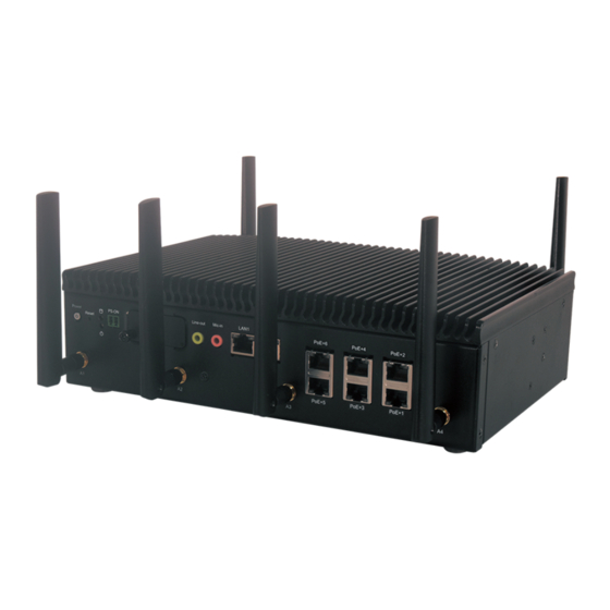
- Page 10 IIOT-I530 is a box PC powered by the 11 generation of Intel® CoreTM i Series CPU (up to i7-1185GRE). The IIoT-I530 makes available imaging-based automated decision-making capabilities that significantly benefit manufacturing industries that require automatic visual inspection and quality control processes. This particular IPC is designed for computing vision and is equipped with features for machine vision, surveillance and compute-intensive video-related applications.
- Page 11 SATA Cable with Power 098W000004000 Wallmount Kit 0P0W000067000 220W AC Adapter TR220MA240 Note When 5G and/or Wi-Fi feature is required, please inform your dealer when issuing purchase order, as the SMA antenna connectors must be pre-assembled on the housing by Lanner.
- Page 12 IIOT-I530 User Manual 11 th Gen Intel® Core I (Up to i7-1185GRE, codenamed TigerLake- UP3) PBF 1.80GHz, MaxTurbo to 4.4GHz Frequency Processor System 4 cores Core Number AMI 256Mbit SPI Flash BIOS BIOS Fanless DDR4 3200 SO-DIMM Technology Memory 64 GB Max.
- Page 13 IIOT-I530 User Manual Description Power Button Power On/Off button Reset Button For software reset LED Indicators Storage/Power Status LED Indicators Power Switch 1x 2-pin Remote Power Switch SIM Card Slot Dual SIM Card slots Audio Jack 1x Line-out and 1x Mic-in Jack LAN Port 2x 2.5GB RJ45 Ethernet Ports...
- Page 14 IIOT-I530 User Manual Description DC Input 1x 2-pin Terminal Block Ground Hole 1x Semi-shearing hole for grounding COM Port 2x DB9 Male Connectors for RS232/422/485 HDMI Port 2x HDMI Ports Multi-IO 1x 20 pin Terminal Block 8 DI (12V) & 8 DO (12V,100mA) Isolation 4x USB 3.0 Type A...
- Page 15 IIOT-I530 User Manual The block diagram indicates how data flows among components on the motherboard.
- Page 16 IIOT-I530 User Manual The pin headers on the motherboard are often associated with important functions. With the shunt (Jumper) pushed down on the designated pins (the pin numbers are printed on the circuit board, surrounding the pin header), certain feature can be enabled or disable. When changing the jumpers, make sure your system is completely turned off.
- Page 17 IIOT-I530 User Manual Normal Program 1-8, 2-7 3-6, 4-5 PIN No. DESCRIPTION 1 ON (Default) SOUT3 2 ON (Default) SIN3 3 OFF NXP_RXD 4 OFF NXP_TXD JTAG1 PIN No. DESCRIPTION +P3V3_STBY NXP_RXD NXP_TXD 1-2 COM1 (Default) PIN No. DESCRIPTION COM_RI1#_P...
-
Page 18: Pin Description
IIOT-I530 User Manual JSPI1 PIN No. DESCRIPTION SPI_HD1# SOC_SPI_CS0#_ROM P3V3_SB_SPI SOC_SPI_MISO_ROM SOC_SPI_IO3_ROM SOC_SPI_CLK_ROM SOC_SPI_MOSI_ROM ESPI1 PIN No. DESCRIPTION ESPI_CLK ESPI_IO1 ESPI_RST# ESPI_IO0 ESPI_CS0# +P3V3 ESPI_IO3 ESPI_IO2 +P3V3_STBY Audio LINE1: DESCRIPTION GND_AUD FRONT_OUT_L FRONT_JD GND_AUD FRONT_OUT_R... - Page 19 IIOT-I530 User Manual Audio MIC1: DESCRIPTION GND_AUD MIC_OUT_L MIC1_JD GND_AUD MIC_OUT_R COM1: Serial Port PIN No. DESCRIPTION COM_DCD1#_P COM_RXD1_P COM_TXD1_P COM_DTR1#_P COM_DSR1#_P COM_RTS1#_P COM_CTS1#_P COM_RI1#_SEL COM2: Serial Port PIN No. DESCRIPTION COM_DCD2#_P COM_RXD2_P COM_TXD2_P COM_DTR2#_P COM_DSR2#_P COM_RTS2#_P COM_CTS2#_P COM_RI2#_SEL DIO1: Isolation Digital Input / Output PIN No.
- Page 20 IIOT-I530 User Manual DI_5 DI_4 DI_7 DI_6 ISO_DO_24V DO_COM DO_COM DO_0 DO_1 DO_3 DO_2 I_COM I_COM MSATA1: MSATA Slots PIN No. DESCRIPTION PIN No. DESCRIPTION +P3V3 SATA1_RXP +P3V3 SATA1_RXN SATA1_TXN SATA1_TXP +P3V3 +P3V3 +P3V3...
- Page 21 IIOT-I530 User Manual JNGFF1: NVME Slot (M-KEY) PIN No. DESCRIPTION PIN No. DESCRIPTION PIN No. DESCRIPTION +P3V3 M2_2_CLKREQ_N CLKOUT_PCIE_N0 +P3V3 PCIE4_RX_N1 PCH_WAKE# PCIE4_RX_N3 CLKOUT_PCIE_P0 PCIE4_RX_P1 PCIE4_RX_P3 GEN4_LED PCIE4_TX_N1 PCIE4_TX_N3 +P3V3 PCIE4_TX_N1 PCIE4_TX_P3 +P3V3 +P3V3 PCIE4_RX_N0 PCIE4_RX_N2 +P3V3 PCIE4_RX_P0 SUSCLK PCIE4_RX_P2...
- Page 22 IIOT-I530 User Manual W_DIS1# USB2_2- UIM1_DAT ANTCTL0 NGFF_LED_1N USB3_M2_T1- UIM1_PWR ANTCTL1 USB3_M2_T1+ V3P3_G1/NC ANTCTL2 M2_1_UIM2_Detect ANTCTL3 PCH_PCIE_RXN5 M2_1_UIM1_DET PERST#M PCH_PCIE_RXP5 V3P3_G1 M2_1_Config_1 PCIE_DIS V3P3_G1 M2_1_Config_0 +P5V/ +P1V8_STBY PCH_PCIE_TXN5 V3P3_G1 WWAN_WAKE_N V3P3_G1/NC PCH_PCIE_TXP5 V3P3_G1 M2_1_DPR PERST#1 M2_1_Config_2 M2_E_KEY1: M.2 Slots (E-KEY) PIN No.
- Page 23 IIOT-I530 User Manual CNV_WR_D0_DP CL_CLK CNVI_WT_D0P PCH_PCIE_RXN9 GPP_F6 CNV_WR_CLKN CNV_MFUART2_TXD CNVI_WT_CLKN CNV_UART0_RXD CLKOUT_PCIE_P2 +P3V3 CNV_WR_CLKP CNV_MFUART2_RXD CNVI_WT_CLKP CLKOUT_PCIE_N2 +P3V3 SUSCLK...
- Page 24 IIOT-I530 User Manual To reduce the risk of personal injury, electric shock, or damage to the unit, please remove all power connections to completely shut down the device and wear ESD protection gloves when handling the installation steps. 1. Power off the system and disconnect the power cord.
- Page 25 IIOT-I530 User Manual To protect the additional electronic components (e.g. RAMs, Module cards) on the motherboard, we have included a partitions and thermal pads kit. Thermal pads placed between electronic component parts help to efficiently dissipate heat, resulting in a better cooling situation.
- Page 26 IIOT-I530 User Manual The motherboard supports 2x DDR4 3200MHz SO-DIMM, up to 64GB, for additional system memory. Please follow the steps for installation. 1. Power off the system, turn the system around, and open the bottom chassis cover. Locate the DIMM socket on the motherboard.
- Page 27 IIOT-I530 User Manual 5. Repeat the steps to insert the top DIMM module. 6. After the top DIMM module has been securely inserted, a thermal pad needs to be placed over it. Remove the protective film from Thermal Pad B (included in Partition & Thermal Pad Kit), and gently place on the module surface.
- Page 28 IIOT-I530 User Manual The system supports one M.2 M-Key NVMe SSD card for additional memory storage. Please follow the steps for installation. 1. Power off the system, turn the system over, and open the bottom chassis cover. Locate the M.2 slot on the motherboard.
- Page 29 IIOT-I530 User Manual 5. Next, thermal pad placement. Remove the protective film from Thermal Pad C (included in Partition & Thermal Pad Kit), and gently place on the module surface. 6. If a 5G and/or Wi-Fi module will not be added, then place metal Partition B (included in Partition &...
- Page 30 Note When 5G feature is required, please inform your dealer when issuing purchase order, as the four SMA antenna connectors must be pre-assembled on the housing by Lanner. 1. Power off the system, turn the system around, and open the bottom chassis cover.
- Page 31 IIOT-I530 User Manual 6. Next, thermal pad placement. Remove the protective film from Thermal Pad D (included in Partition & Thermal Pad Kit), and gently place on the module surface. Installing 5G Antennas Front Panel Rear Panel...
- Page 32 IIOT-I530 User Manual 1. Locate the four (4) antenna RF cables (pre-assembled). Locate the four (4) IPEX connectors on the 5G module 5G Module Card card. 2. Connect A1, A4, A5, A6 RF cables to the 5G module card. 5G Module Card...
- Page 33 IIOT-I530 User Manual 3. If a Wi-Fi module will not be added, then place metal Partition B (included in Partition & Thermal Pad Kit), over the 5G module, and secure with one (1) screw on the partition and two (2) screws on the side panel.
- Page 34 Note When Wi-Fi feature is required, please inform your dealer when issuing purchase order, as the two SMA antenna connectors must be pre-assembled on the housing by Lanner. 1. Power off the system, turn the system around, and open the bottom chassis cover.
- Page 35 IIOT-I530 User Manual Installing Wi-Fi Antennas Front Panel 1. Locate the two (2) antenna RF cables (pre-assembled). Locate the two (2) IPEX connectors on the Wi-Fi module card. 2. Connect A2, A3 RF cables to the Wi- Fi module card.
- Page 36 IIOT-I530 User Manual 3. Then place metal Partition B (included in Partition & Thermal Pad Kit), over the Wi-Fi module, and secure with one (1) screw on the partition and two (2) screws on the side panel. 4. Screw on the two (2) antennas to the...
- Page 37 IIOT-I530 User Manual The system supports one mSATA SSD module card for additional memory storage. Please follow the steps for installation. 1. Power off the system, turn the system around, and open the bottom chassis cover. 2. Locate the mSATA slot on the motherboard.
- Page 38 IIOT-I530 User Manual The system supports one 2.5” SATA HDD/SSD drive bay for additional data storage. Please follow the steps for installation. 1. Power off the system, turn the system onto its bottom, open the bottom chassis cover. Locate the 2.5”...
- Page 39 IIOT-I530 User Manual 4. Connect the SATA 7-pin signal cable and the SATA 4-pin power cable to their corresponding connectors on the motherboard. 5. Plug the standard 7+15 SATA connector to the SSD.
- Page 40 IIOT-I530 User Manual The system can be mounted on a flat surfaced wall. Please take the following into considerations when mounting the system onto the wall. Note: All pictures shown are for illustration purposes only, actual product may vary due to specific model or enhancement.
- Page 41 IIOT-I530 User Manual On the wall, measure the exact place where you want to hang the system, and drill four holes that match the four mounting holes on both brackets. Insert four anchoring bolts into the holes. Align the four mounting holes on the system’s brackets with the four anchoring bolts you just installed on the wall.
- Page 42 IIOT-I530 User Manual The system has AMI BIOS built-in, with a SETUP utility that allows users to configure required settings or to activate certain system features. Pressing the <Tab> or <Del> key immediately allows you to enter the Setup utility.
- Page 43 IIOT-I530 User Manual Setup main page contains BIOS information and project version information. Feature Description BIOS Vendor: American Megatrends Core Version: AMI Kernel version, CRB code base, X64 Compliancy: UEFI version, PI version BIOS Information Project Version: BIOS release version...
- Page 44 IIOT-I530 User Manual Select the Advanced menu item from the BIOS setup screen to enter the “Advanced” setup screen. Users can select any of the items in the left frame of the screen.
- Page 45 IIOT-I530 User Manual Feature Options Description Intel (VMX) Enabled When enabled, a VMM can utilize the additional hardware Virtualization Disabled capabilities provided by Vanderpool Technology. Technology Active Processor Number of cores to enable in each processor package. Cores Enabled Hyper-Threading Enable or Disable Hyper-Threading Technology.
- Page 46 IIOT-I530 User Manual Feature Options Description Enabled ME State Configure Management Engine Technology Parameters Disabled...
- Page 47 IIOT-I530 User Manual Feature Options Description Me FW Image Enabled Enable/Disable ME FW Image Re-Flash function. Re-Flash Disabled Enabled FW Update Enable/Disable ME FW Update function. Disabled...
- Page 48 IIOT-I530 User Manual Feature Options Description Automatic OEM Key Enabled When enabled, BIOS will automatically send HECI command to Revocation Disabled revoke OEM keys. Invoke OEM Key Enabled When enabled, BIOS will automatically send HECI command to Revocation Disabled revoke OEM keys.
- Page 49 IIOT-I530 User Manual Feature Options Description Enables or Disables BIOS support for security device. O.S. will not Security Device Enabled show Security Device. TCG EFI protocol and INT1A interface will not Support Disabled be available. Enabled SHA-1 PCR Bank Enables or Disables SHA-1 PCR Bank.
- Page 50 IIOT-I530 User Manual Enabled SHA384 PCR Bank Enables or Disables SHA384 PCR Bank. Disabled SM3_256 PCR Enabled Enables or Disables SM3_256 PCR Bank. Bank Disabled Schedules an Operation for the Security Device. NOTE: Your Pending None computer will reboot during restart in order to change State of...
- Page 51 IIOT-I530 User Manual...
- Page 52 IIOT-I530 User Manual Feature Options Description Enabled Serial Port Enables or Disables Serial Port (COM) Disabled Device Settings IO=3F8h; IRQ = 4 Loopback RS232 COM1 MODE Select Com Mode as RS232/RS485 RS485 Half Duplex RS485/422 Full Duplex COM1 Enabled COM RS-422/485 Receiver Termination...
- Page 53 IIOT-I530 User Manual Feature Options Description Enabled Serial Port Enables or Disables Serial Port (COM) Disabled Device Settings IO=2F8h; IRQ = 3 Loopback RS232 COM1 MODE Select Com Mode as RS232/RS485 RS485 Half Duplex RS485/422 Full Duplex COM1 Enabled COM RS-422/485 Receiver Termination...
- Page 54 IIOT-I530 User Manual Feature Description CPU temperature This value reports the CPU temperature. System temperature This value reports the System temperature. VCORE This value reports the CPU VCORE. 3.3V_S This value reports the 3.3V_S Input voltage. This value reports the 5V Input voltage.
- Page 55 IIOT-I530 User Manual Feature Options Description Enabled Watch Dog Timer Enable or Disable Watch Dog function Disabled...
- Page 56 IIOT-I530 User Manual Feature Options Description COM0 Enabled Console Enables or disables Console Redirection Disabled Redirection COM1 Enabled Console Enables or disables Console Redirection Disabled Redirection...
- Page 57 IIOT-I530 User Manual Feature Options Description ANSI: Extended ASCII char set. VT100 VT100: ASCII char set. VT100+ Terminal Type VT100+: Extends VT100 to support color, function keys, etc. VT-UTF8 VT-UTF8: Uses UTF8 encoding to map Unicode chars onto 1 ANSI or more bytes.
- Page 58 IIOT-I530 User Manual VT-UTF8 Combo Disabled Enable VT-UTF8 Combination Key Support for ANSI/VT100 Key Support Enabled terminals Disabled With this mode enabled only text will be sent. This is to Recorder Mode Enabled capture Terminal data. Disabled Resolution 100x31 Enables or disables extended terminal resolution.
- Page 59 IIOT-I530 User Manual Feature Options Description COM0 Select a COM port to display redirection of Legacy OS and Redirection COM Port COM1 Legacy OPROM Messages 80x24 On Legacy OS, the Number of Rows and Columns supported Resolution 80x25 redirection. When...
- Page 60 IIOT-I530 User Manual Feature Options Description Enables Legacy USB support. Enabled Auto option disables legacy support if no USB devices are Legacy USB Support Disabled connected; Auto Disabled option will keep USB devices available only for EFI applications. Enabled This is a workaround for OSes without XHCI hand-off support. The...
- Page 61 IIOT-I530 User Manual Feature Options Description Disabled Network Stack Enable/Disable UEFI Network Stack Enable Disabled Enable/Disable IPv4 PXE boot support. If disabled, IPv4 IPv4 PXE Support Enable PXE boot support will not be available. Disabled Enable/Disable IPv4 HTTP boot support. If disabled, IPv4...
- Page 62 Feature Options Description Disabled CSM Support Enables or disables CSM Support Enabled UEFI and Legacy Boot option filter This option controls Legacy/UEFI ROMs priority Legacy only UEFI only Do Not Launch Network Controls the execution of UEFI and Legacy PXE OpROM UEFI Legacy Do Not Launch...
- Page 63 IIOT-I530 User Manual...
- Page 64 IIOT-I530 User Manual Select the Chipset menu item from the BIOS setup screen to enter the “Chipset” setup screen. Users can select any of the items in the left frame of the screen.
- Page 65 IIOT-I530 User Manual Feature Options Description Enabled VT-d VT-d capability Disabled Enabled X2APIC Opt Out Enable/Disable X2APIC_OPT_OUT bit Disabled Enable/Disable above 4GB MemoryMappedIO BIOS Above 4GB MMIO Enabled assignment This is disabled automatically when Aperture BIOS assignment Disabled Size is set to 2048MB...
- Page 66 IIOT-I530 User Manual Feature Options Description Maximum Memory Auto Maximum Memory |Frequency Selections in Mhz. Frequency Maximum Value of TOLUD. Dynamic assignment would Max TOLUD Dynamic adjust TOLUD automatically based on largest MMIO length of installed graphic controller DDR MEMORY...
- Page 67 IIOT-I530 User Manual Feature Options Description Restore AC Power Power On Specify what state to go to when power is re-applied Loss Power Off after a power failure (G3 state).
- Page 68 IIOT-I530 User Manual Feature Options Description Enabled SATA Controller(s) Enable/Disable SATA Device. Disabled AHCI SATA Mode Selection Determines how SATA controller(s) operate. Intel RST Enabled Port 0 Enable or Disable SATA Port Disabled...
- Page 69 IIOT-I530 User Manual Enabled Hot Plug Designates this port as Hot Pluggable. Disabled Enabled External Marks this port as external. Disabled If enabled for any of ports Staggerred Spin Up will be Enabled performed and only the drives which have this option...
- Page 70 IIOT-I530 User Manual If enabled for any of ports Staggerred Spin Up will be Enabled performed and only the drives which have this option Spin Up Device Disabled enabled will spin up at boot. Otherwise all drives spin up at boot.
- Page 71 IIOT-I530 User Manual Feature Options Description Enable xDCI Support Enable/Disable xDCI (USB OTG Device). Disable USB3 Link Speed GEN1 This option is to select USB3 Link Speed GEN1 or GEN2 Selection GEN2...
- Page 72 IIOT-I530 User Manual Feature Options Description Enabled Enable will lock bytes 38h-3Fh in the lower/upper 128-byte RTC Memory Lock Disabled bank of RTC RAM Enabled Enable/Disable the PCH BIOS Lock Enable feature. Required BIOS Lock Disabled to be enabled to ensure SMM protection of flash.
- Page 73 IIOT-I530 User Manual Select the Security menu item from the BIOS setup screen to enter the “Security” setup screen. Users can select any of the items in the left frame of the screen. Feature Description If ONLY the Administrator's password is set, it only limits access Administrator Password to Setup and is only asked for when entering Setup.
- Page 74 IIOT-I530 User Manual Feature Options Description Secure Boot feature is Active if Secure Boot is Enabled, Platform Disabled Secure Boot Key (PK) is enrolled and the System is in User mode. The mode Enabled change requires platform reset Secure Boot mode options: Standard or Custom. In Custom...
- Page 75 IIOT-I530 User Manual Feature Options Description Factory Key Disabled Install factory default Secure Boot keys after the platform Provision Enabled reset and while the System is in Setup mode Restore Factory Force System to User Mode. Install factory default Secure...
- Page 76 IIOT-I530 User Manual Select the Boot menu item from the BIOS setup screen to enter the “Boot” setup screen. Users can select any of the items in the left frame of the screen. Feature Options Description The number of seconds to wait for setup activation key.
- Page 77 Select the Save and Exit menu item from the BIOS setup screen to enter the “Save and Exit” setup screen. Users can select any of the items in the left frame of the screen. ■ Discard Changes and Exit Select this option to quit Setup without saving any modifications to the system configuration. The following window will appear after the “Discard Changes and Exit”...
- Page 78 IIOT-I530 User Manual ■ Save Changes and Reset When Users have completed the system configuration changes, select this option to save the changes and reset from BIOS Setup in order for the new system configuration parameters to take effect. The following window will appear after selecting the “Save Changes and Reset”...
- Page 79 IIOT-I530 User Manual 1. All products are under warranty against defects in materials and workmanship for a period of one year from the date of purchase. 2. The buyer will bear the return freight charges for goods returned for repair within the warranty period;...
- Page 80 IIOT-I530 User Manual When requesting RMA service, please fill out the following form. Without this form enclosed, your RMA cannot be processed.
Need help?
Do you have a question about the IIOT-I530 and is the answer not in the manual?
Questions and answers