Advertisement
Quick Links
Advertisement

Related Manuals for Lanner NCA-1010


Summary of Contents for Lanner NCA-1010
- Page 1 Network Computing NCA-1010 User Manual Version: 1.5 Date of Release: 2019/03/22...
- Page 2 NCA-1010 User Manual The icons are used in the manual to serve as an indication of interest topics or important messages. Below is a description of these icons: Note: This check mark indicates that there is a note of interest and is something that you should pay special attention to while using the product.
- Page 3 This product has passed the CE test for environmental specifications. Test conditions for passing included the equipment being operated within an industrial enclosure. In order to protect the product from being damaged by ESD (Electrostatic Discharge) and EMI leakage, we strongly recommend the use of CE-compliant industrial enclosure products.
- Page 4 NCA-1010 User Manual Risk of Explosion if Battery is replaced by an incorrect type. Dispose of used batteries according to the instructions. Installation only by a trained electrician or only by an electrically trained person who knows all English Installation and Device Specifications which are to be applied.
- Page 5 conformément aux instructions des fournisseurs de composants sans fil, il risque de provoquer des interférences dans les communications radio. Risque d’explosion si la pile est remplacée par une autre d’un mauvais type. Jetez les piles usagées conformément aux instructions. L’installation doit être effectuée par un électricien formé ou une personne formée à l’électricité connaissant toutes les spécifications d’installation et d’appareil du produit.
- Page 6 NCA-1010 User Manual Desserrez la vis du terminal de mise à la terre. Branchez le câble de mise à la terre à la terre. L’appareil protection pour source d’alimentation CC doit fournir 30 A de courant. Cet appareil de protection doit être branché à la...
- Page 7 Version Date Descriptions 2015/03/25 Preliminary 2015/05/18 Added Appendix 2015/05/25 Modified specifications Added safety guidelines 2015/06/19 Modified power adapter information 2015/08/11 Modified reset button to “hardware reset only” 2015/08/31 Added pin assignments 2016/04/08 Official release 2016/06/02 Added reset jumper on motherboard due to changes in motherboard design 2016/06/13 Modified console pin assignments...
-
Page 8: Table Of Contents
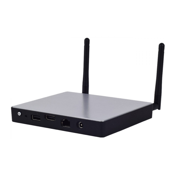
NCA-1010 User Manual System Specifications ......................... 10 Front Panel ..........................12 Rear Panel ........................... 13 Motherboard Layout ........................14 Block Diagram ..........................16 Internal Jumper & Connectors ....................17 Preparing the Hardware Installation ..................21 Installing the System Memory ....................21 Installing Mini PCIe Wireless Module .................. - Page 9 Despite its compact size, NCA-1010 delivers rich I/O connectivity and scalability. In terms of scalability, NCA-1010 comes with one HDMI port for high definition display, one console port for device network management, three LAN ports for network connections, two USB ports (one in USB 2.0 and another in USB 3.0 specifications) for external devices, and one antenna hole for signal reception.
- Page 10 NCA-1010 User Manual Intel® Bay Trail E3815 or E3825 CPU Frequency 1.46 GHz E3815 CPU: single core Processor System Core Number E3825 CPU: dual cores BIOS AMI SPI Flash BIOS Chipset Thermal Fanless Technology DDR3L 1067 MHz non-ECC Memory Max. Capacity...
- Page 11 Introduction Input* AC 100~240V@50~60 Hz Microsoft Windows Windows 7, Windows 8, WES 7, WES 8 Driver Support Linux Linux (Fedora 18/Yocto) CE Class B, FCC Class A, RoHS Certification Safety...
- Page 12 NCA-1010 User Manual Description Description Power switch Reset USB 2.0 port HDMI output port Console Port Power input...
- Page 13 Introduction Description 3 x Ethernet LAN ports in RJ-45 connectors USB 3.0 port, backward compatible with USB 2.0 Antenna hole...
-
Page 14: Motherboard Layout
NCA-1010 User Manual The motherboard layout shows the connectors and jumpers on the board. Refer to the following picture as a reference of the pin assignments and the internal connectors. - Page 15 Introduction...
- Page 16 NCA-1010 User Manual...
- Page 17 Introduction USB 2.0 port (J1N2): Signal Signal VCC 5V USB 3.0 port (J4P1) Signal Signal VCC 5V USB3_RX- USB3_RX+ USB3_TX- USB3_TX+ Console Port (J1M5): The console port is defined in serial interface. Signal Signal Transmitted Data (TxD) Received Data (RxD)
- Page 18 NCA-1010 User Manual mSATA socket (J3M1): Signal Signal Signal Signal 3.3V 3.3V 3.3V 3.3V 3.3V...
- Page 19 Introduction Mini-PCI Express socket (J3M2): Signal Signal Signal Signal WAKE 3.3V 1.5V CLKREQ CLK- CLK+ RESET PCIE_RX- 3.3V PCIE_RX+ 1.5V SMB_CLK PCIE_TX- SMB_DAT PCIE_TX+ USB_D- USB_D+ 3.3V 3.3V 1.5V 3.3V LAN Ports ( J1M2/J1M3/J1M4)
- Page 20 NCA-1010 User Manual Signal Signal Signal Signal MDI0+ MDI0- MDI1+ MDI2+ MDI2- MDI1- MDI3+ MDI3- Reset Pin Header Signal Signal Reset HDMI Display Port (J4N1): Signal Signal DAT2+ DATA2- DATA1+ DATA1- DATA0+ DATA0- CLK+ CLK- HOT_PLUG_DET...
- Page 21 (3) Do NOT pile items on top of the system to prevent damages due to this improper use. Lanner is not liable for damages caused by improper use of the product. The motherboard supports DDR3L non-ECC DIMM memory. Please follow the steps to install the DIMM module.
- Page 22 NCA-1010 User Manual NCA-1010 motherboard is designed with a mini-PCIe wireless module socket. Please follow the steps below for installation. Locate the mini-PCIe socket and align the notches between the socket and the module. Then insert the module as shown in the image.
- Page 23 Hardware Setup NCA-1010 motherboard is designed with an mSATA Mini socket for storage purpose. Please follow the steps below for installation. Locate the mSATA Mini socket and align the notches between the socket and the module. Then insert the module as shown in the image.
-
Page 24: Main
BIOS load optimized default values save configurations and exit BIOS <Esc> exit the current screen *No "Restore AC Power Loss" option in NCA-1010 BIOS setting. The parameter is set as "Power On" by default. - Page 25 Setup main page contains BIOS information and project version information. Feature Description BIOS Vendor: American Megatrends Core Version: AMI Kernel version, CRB code base, X64 BIOS Compliancy: UEFI version, PI version Information Project Version: BIOS release version Access Level: Administrator / User Memory Total Memory: Total Memory size.
-
Page 26: Advanced
NCA-1010 User Manual Select the Advanced menu item from the BIOS setup screen to enter the “Advanced” setup screen. Users can select any of the items in the left frame of the screen. Feature Options Description Disabled PXE Function Enable LAN1... - Page 28 NCA-1010 User Manual Feature Options Description COM0 Enabled Console Enables or disables Console Redirection Disabled Redirection...
- Page 29 Console Redirection Settings Feature Options Description VT100: ASCII char set VT100 VT100+:Extends VT100 to support color, function VT100+ keys, etc. Terminal Type VT-UTF8 VT-UTF8:Uses UTF8 encoding to map Unicode ANSI chars onto 1 or more bytes ANSI: Extended ASCII char set 9600 19200 Selects serial port transmission speed.
- Page 30 NCA-1010 User Manual Disabled With this mode enabled, only text will be sent. This Recorder Mode Enabled is to capture Terminal data. Disabled Resolution 100x31 Enables or disables extended terminal resolution Enabled Legacy OS 80x24 On Legacy OS, the Number of Rows and Columns...
- Page 31 Feature Options Description Socket 0 CPU None Socket specific CPU Information Information Disabled Limit CPUID Maximum Disabled for Windows XP Enabled XD can prevent certain classes of malicious buffer overflow attacks when combined Disabled Execute Disable Bit with a supporting OS (Windows Server Enabled 2003 SP1, Windows XP SP2, SuSE Linux 9.2, RedHat Enterprise 3 Update 3.)
- Page 32 NCA-1010 User Manual Feature Options Description Disabled Serial-ATA (SATA) Enable / Disable Serial ATA Enabled Disabled SATA Test Mode Test Mode enable / disable. Enabled Gen1 SATA Speed Support SATA Speed Support Gen1 or Gen2 Gen2 IDE Mode SATA Mode...
- Page 33 Feature Options Description Enables or disables BIOS support for security device. By disabling this function, Security Device Disabled OS will not show Security Device. TCG EFI Support Enabled protocol and INT1A interface will not be available.
- Page 34 NCA-1010 User Manual Trusted Computing Feature Options Description Enables or disables BIOS support for security device. Security Device Disabled By disabling this function, OS will not show Security Support Enabled Device. TCG EFI protocol and INT1A interface will not be available.
- Page 35 Feature Options Description Enables Legacy USB support. Enabled Auto option disables legacy support if no Legacy USB Support Disabled USB devices are connected; Auto Disabled option will keep USB devices available only for EFI applications. Enabled Enable/Disable USB3.0 (XHCI) Controller USB3.0 Support Disabled Support.
- Page 36 NCA-1010 User Manual 5 sec command time-out 10 sec 20 sec Maximum time the device will take before it properly reports itself to the Host Auto Device power-up delay Controller. Auto uses default value: for a Manual Root port, it is 100 ms, for a Hub port the...
-
Page 37: Chipset
Select the Chipset menu item from the BIOS setup screen to enter the Platform Setup screen. Users can select any of the items in the left frame of the screen. - Page 38 NCA-1010 User Manual Feature Options Description Dynamic 1 GB 1.25 GB 1.5 GB 1.75 GB Max TOLUD. Maximum Value of TOLUD. 2 GB 2.25 GB 2.5 GB 2.75 GB 3 GB...
- Page 39 Feature Options Description High Precision Enabled Enable or Disable the High Precision Event Timer. Timer Disabled...
-
Page 40: Usb Configuration
NCA-1010 User Manual USB Configuration Feature Options Description Enabled Mode of operation of xHCI controller XHCI Mode Disabled Auto USB 2.0(EHCI) Disabled Control the USB EHCI (USB 2.0) functions. One EHCI Support Enabled controller must always be enabled Disabled Enable / Disable USB Port 0... -
Page 41: Security
Select the Security menu item from the BIOS setup screen to enter the Security Setup screen. Users can select any of the items in the left frame of the screen. Feature Description If ONLY the Administrator's password is set, it only limits access to Setup and is only asked for when Administrator Password entering Setup. -
Page 42: Boot Menu
NCA-1010 User Manual Select the Boot menu item from the BIOS setup screen to enter the Boot Setup screen. Users can select any of the items in the left frame of the screen. Feature Options Description The number of seconds to wait for setup Setup Prompt Timeout activation key. -
Page 43: Save And Exit Menu
Select the Save and Exit menu item from the BIOS setup screen to enter the Save and Exit Setup screen. Users can select any of the items in the left frame of the screen. ■ Discard Changes and Exit Select this option to quit Setup without saving any modifications to the system configuration. The following window will appear after the “Discard Changes and Exit”... - Page 44 NCA-1010 User Manual ■ Restore Defaults Restore default values for all setup options. Select “Yes” to load Optimized defaults. PS: The items under Boot Override were not same with image. It should depend on devices connect on system.
- Page 45 Appendix All products are under warranty against defects in materials and workmanship for a period of one year from the date of purchase. The buyer will bear the return freight charges for goods returned for repair within the warranty period; whereas the manufacturer will bear the after service freight charges for goods returned to the user.
- Page 46 NCA-1010 User Manual...
Need help?
Do you have a question about the NCA-1010 and is the answer not in the manual?
Questions and answers