Advertisement
Quick Links
Advertisement

Related Manuals for Lanner IIOT-I531


Summary of Contents for Lanner IIOT-I531
- Page 1 Embedded Computing Platform IIOT-I531 User Manual Version: 1.0 Date of Release: 2023-01-19...
- Page 2 - assumed to be qualified in the servicing of computer equipment, such as professional system integrators, or service personnel and technicians. The latest version of this document can be found on Lanner’s official website, available either through the product page or through the Lanner Download Center page with a login account and password.
- Page 3 IIOT-I531 User Manual Taiwan Corporate Headquarters China Lanner Electronics Inc. Beijing L&S Lancom Platform Tech. Co., Ltd. 7F, No.173, Sec.2, Datong Rd. Guodong LOFT 9 Layer No. 9 Huinan Road, Xizhi District, New Taipei City 22184, Huilongguan Town, Changping District, Beijing...
- Page 4 IIOT-I531 User Manual Intel® and Intel® Core are trademarks of Intel Corporation or its subsidiaries in the U.S. and/or other countries. Microsoft Windows and MS-DOS are registered trademarks of Microsoft Corp. All other product names or trademarks are properties of their respective owners.
- Page 5 IIOT-I531 User Manual Follow these guidelines to ensure general safety: Keep the chassis area clear and dust-free during and after installation. Do not wear loose clothing or jewelry that could get caught in the chassis. Fasten your tie or scarf and roll up your sleeves.
- Page 6 The installation of this product must be performed by trained specialists; otherwise, a non-specialist might create the risk of the system’s falling to the ground or other damages. Lanner Electronics Inc. shall not be held liable for any losses resulting from insufficient strength for supporting the system or use of inappropriate installation components.
- Page 7 IIOT-I531 User Manual attention should be given to supply connections other than direct connections to the branch circuit (e.g. use of power strips). Installation & Operation: This equipment must be grounded. The power cord for product should be connected to a socket-outlet with earthing connection.
- Page 8 IIOT-I531 User Manual Before turning on the device, ground the grounding cable of the equipment. Proper grounding (grounding) is very important to protect the equipment against the harmful effects of external noise and to reduce the risk of electrocution in the event of a lightning strike. To uninstall the equipment, disconnect the ground wire after turning off the power.
- Page 9 IIOT-I531 User Manual Key Features ............................. 11 Package Content..........................11 Ordering Information ........................11 Specifications............................ 12 Front Panel ............................14 Rear Panel ............................15 Motherboard Information........................ 16 Internal Jumpers and Connector ...................... 17 Open the Chassis ..........................22 Installing mSATA Storage Card (Optional) ..................23 Installing Wi-Fi Module (Optional) ....................
- Page 10 IIOT-I531 User Manual Boot Menu ............................72 Save and Exit Menu .......................... 73 Warranty Policy ..........................76...
- Page 11 IIOT-I531 User Manual The IIoT-I531 makes available imaging-based automated decision-making capabilities that greatly benefit industries and manufacturing that require automatic visual inspection and quality control processes; such capabilities can also be relied upon for surveillance, security, guiding robotics collaboration and automating vehicle driving.
- Page 12 IIOT-I531 User Manual Intel® Core i (Up to i7-1185GRE), Codenamed TigerLake-UP3 PBF1.80GHz, MaxTurbo to 4.40GHz Frequency Processor System Core Number AMI SPI Flash BIOS BIOS Fanless DDR4 3200 IBECC SO-DIMM Technology Memory Up to 64 GB Max. Capacity 2x 260-pin SO-DIMM Socket Intel®...
- Page 13 IIOT-I531 User Manual Debian 11 pre-installed Linux OS Support Win 10 IoT Windows FCC/CE Class A, UL Certification C1D2 in IP54 Box (Optional) Safety...
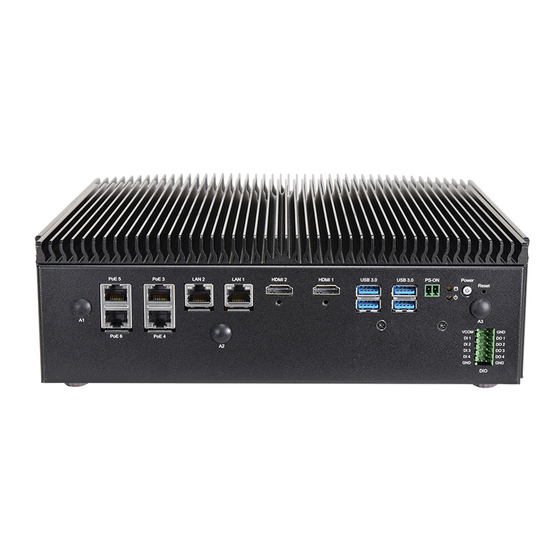
- Page 14 IIOT-I531 User Manual Description 4x 100/1000/2500Mbps IEEE802.3af/at PoE 2.5GigBE (+) w/ surge 2KV PoE Port protection under maximum 60W power budget (Port 2-5 / PCIe 3.0) without isolation Ethernet Port 2x 10/100/1000/2500Mbps RJ45 LAN Ports w/ TSN Display Port 2x HDMI Ports w/ lock USB Port 4x USB 3.0 Type A Ports...
- Page 15 IIOT-I531 User Manual Description 1x 2x5-Pin Terminal block for isolated 2x CAN 2.0A/B (optional for RS232/422/485 COM3, COM4 Ports) RS-232 SOUT RS-422 RS-485 RS-485 COM Port RS-232 SOUT RS-422 RS-485 RS-485 1x PCIe 3.0 x1 FHHL w PCIe x4 Connector (supports maximum 60W...
- Page 16 IIOT-I531 User Manual The block diagram indicates how data flows among components on the motherboard.
- Page 17 IIOT-I531 User Manual The pin headers on the motherboard are often associated with important functions. With the shunt (Jumper) pushed down on the designated pins (the pin numbers are printed on the circuit board, surrounding the pin header), certain feature can be enabled or disable. When changing the jumpers, make sure your system is...
- Page 18 IIOT-I531 User Manual PW1 (+24V) Signal DC_GND DC_IN JCOMS1: RTC Reset 1-2: Save CMOS (Default) 2-3: Clear CMOS Signal RTC_RST# JCOMS2: SRTC Secured RTC Reset 1-2: Save ME RTC 2-3: Clear ME RTC Signal SRTC_RST# J1: For Program MCU (Debug/Burn in code)
- Page 19 IIOT-I531 User Manual CON5 Signal +P3V3_STBY NXP_RXD NXP_TXD Signal COPEN# Signal INTRUSION# JSPI1 Signal SPI_HD1# SOC_SPI_CS0#_R P3V3_SB_SPI SOC_SPI_MISO_R SOC_SPI_IO3_R SOC_SPI_CLK_R SOC_SPI_MOSI_R COM1 Signal COM_DCD1_#_L COM_RXD1_L COM_TXD1_L COM_DTR1_#_L COM_DSR1_#_L...
- Page 20 IIOT-I531 User Manual COM_RTS1_#_L COM_CTS1_#_L COM_RI1#_L COM2 Signal COM_DCD2_#_L COM_RXD2_L COM_TXD2_L COM_DTR2_#_L COM_DSR2_#_L COM_RTS2_#_L COM_CTS2_#_L COM_RI2#_L ESPI1: Signal Signal ESPI_CLK ESPI_IO1 ESPI_RST# ESPI_IO0 ESPI_CS0# +P3V3 ESPI_IO3 ESPI_IO2 +P3V3_STBY SATA_PWR1 Signal +P12V +P5V...
- Page 21 IIOT-I531 User Manual IO Board Signal ICSP_VPP1 +P3V3 ICSP_DAT1 ICSP_CLK1 Signal ICSP_VPP2 +P3V3 ICSP_DAT2 ICSP_CLK2 Signal Signal GND_ISOCOM1 GND_ISOCOM2 COM1_ISO_422TXD-_485D- COM2_ISO_422TXD-_485D- COM1_ISO_422TXD+_485+ COM2_ISO_422TXD+_485D+ Signal Signal GND_ISODIO GND_ISODIO DI_4 DI_3 DI_2 DI_1 GND_ISODIO VCOM...
- Page 22 IIOT-I531 User Manual To reduce the risk of personal injury, electric shock, or damage to the unit, please remove all power connections to completely shut down the device and wear ESD protection gloves when handling the installation steps. 1. Power off the system and disconnect the power cord.
- Page 23 IIOT-I531 User Manual The system supports one mSATA storage card for additional memory storage. Please follow the steps for installation. 1. Power off the system, turn the system around, and open the bottom chassis cover. Remove the metal bracket by loosening the one (1) screw on the bracket, and the two (2) screws on the front panel.
- Page 24 IIOT-I531 User Manual 5. Push down on the module card and secure it with a screw. 6. Next, thermal pad placement. Remove the protective film on the Thermal Pad (included in accessory pack) and gently place on the mSATA module.
- Page 25 IIOT-I531 User Manual The system supports one M.2 E-key slot for a Wi-Fi module card, an optional accessory. Wi-Fi module requires two antennas. Please follow the steps to install the Wi-Fi module. 1. Power off the system, turn the system around, and open the bottom chassis cover.
- Page 26 IIOT-I531 User Manual Next, thermal placement. Remove the protective film on the Thermal Pad (included in accessory pack) and gently place on the Wi-Fi module. 7. Make sure to place the metal bracket back on top and secure with three (3) screws, after installing the RF antenna cables.
- Page 27 IIOT-I531 User Manual The motherboard provides one M.2 B-Key slot for a 4G LTE/ 5G module card, an optional additional accessory. 5G module will require four antennas. Please follow the installation procedures for the 5G module. 1. Power off the system, turn the system around, and open the bottom chassis cover.
- Page 28 IIOT-I531 User Manual 5. Insert the 5G module card pins at 30 degrees into the socket until it is fully seated. 6. Push down on the module card and secure it with a screw. 7. Then, place another thermal pad on the module card.
- Page 29 IIOT-I531 User Manual 2. Connect the RF cables to the IPEX connectors on the 5G module and screw the other end of the cables in the antenna holes. 3. Then, screw on the four (4) antennas on the front and rear panel of the system.
- Page 30 IIOT-I531 User Manual The SIM slot on the side panel supports dual Nano SIM cards. The SIM socket supports the push-push mechanism, allowing inserting and ejecting the SIM card to be as easy as one push. 1. Locate the SIM card cover on the side panel.
- Page 31 IIOT-I531 User Manual The system supports one 2.5” HDD/SSD drive for additional data storage. Please follow the steps for installation. 1. The HDD/SSD Kit includes: 1x 2.5” SSD 1x SATA Cables 2.5” SSD SATA Cables 2. Power off the system and open the bottom chassis cover.
- Page 32 IIOT-I531 User Manual The system can be mounted on a flat surfaced wall. Please take the following into considerations when mounting the system onto the wall. Note: All pictures shown are for illustration purposes only, actual product may vary due to specific model or enhancement.
- Page 33 IIOT-I531 User Manual On the wall, measure the exact place where you want to hang the system, and drill four holes that match the four mounting holes on both brackets. Insert four anchoring bolts into the holes. Align the four mounting holes on the system’s brackets with the four anchoring bolts you just installed on the wall.
- Page 34 IIOT-I531 User Manual The system has AMI BIOS built-in, with a SETUP utility that allows users to configure required settings or to activate certain system features. Pressing the <Tab> or <Del> key immediately allows you to enter the Setup utility.
- Page 35 IIOT-I531 User Manual Setup main page contains BIOS information and project version information. Feature Description BIOS Vendor: American Megatrends Core Version: AMI Kernel version, CRB code base, X64 Compliancy: UEFI version, PI version BIOS Information Project Version: BIOS release version...
- Page 36 IIOT-I531 User Manual Select the Advanced menu item from the BIOS setup screen to enter the “Advanced” setup screen. Users can select any of the items in the left frame of the screen.
- Page 37 IIOT-I531 User Manual Feature Options Description Intel (VMX) Enabled When enabled, a VMM can utilize the additional hardware Virtualization Disabled capabilities provided by Vanderpool Technology. Technology Active Processor Number of cores to enable in each processor package. Cores Enabled Hyper-Threading Enable or Disable Hyper-Threading Technology.
- Page 38 IIOT-I531 User Manual Feature Options Description Enabled ME State Configure Management Engine Technology Parameters Disabled...
- Page 39 IIOT-I531 User Manual Feature Options Description Me FW Image Enabled Enable/Disable ME FW Image Re-Flash function. Re-Flash Disabled Enabled FW Update Enable/Disable ME FW Update function. Disabled...
- Page 40 IIOT-I531 User Manual Feature Options Description Automatic OEM Key Enabled When enabled, BIOS will automatically send HECI command to Revocation Disabled revoke OEM keys. Invoke OEM Key Enabled When enabled, BIOS will automatically send HECI command to Revocation Disabled revoke OEM keys.
- Page 41 IIOT-I531 User Manual Feature Options Description Enables or Disables BIOS support for security device. O.S. will not Security Device Enabled show Security Device. TCG EFI protocol and INT1A interface will not Support Disabled be available. Enabled SHA-1 PCR Bank Enables or Disables SHA-1 PCR Bank.
- Page 42 IIOT-I531 User Manual Enabled SHA384 PCR Bank Enables or Disables SHA384 PCR Bank. Disabled SM3_256 PCR Enabled Enables or Disables SM3_256 PCR Bank. Bank Disabled Schedules an Operation for the Security Device. NOTE: Your Pending None computer will reboot during restart in order to change State of...
- Page 43 IIOT-I531 User Manual Feature Options Description WINDOWS OS Select UART IRQ mode setting for WINDOWS or LINUX OS LINUX COM4 or CAN COM4 or CAN COM4...
- Page 44 IIOT-I531 User Manual Feature Options Description Enabled Serial Port Enables or Disables Serial Port (COM) Disabled Device Settings IO=3F8h; IRQ = 4 Loopback RS232 COM1 MODE Select Com Mode as RS232/RS485 RS485 Half Duplex RS485/422 Full Duplex COM1 Enabled COM RS-422/485 Receiver Termination...
- Page 45 IIOT-I531 User Manual Feature Options Description Enabled Serial Port Enables or Disables Serial Port (COM) Disabled Device Settings IO=2F8h; IRQ = 3 Loopback RS232 COM2 MODE Select Com Mode as RS232/RS485 RS485 Half Duplex RS485/422 Full Duplex COM2 Enabled COM RS-422/485 Receiver Termination...
- Page 46 IIOT-I531 User Manual Feature Options Description Enabled Serial Port Enables or Disables Serial Port (COM) Disabled Device Settings IO=3E8h; IRQ = 7...
- Page 47 IIOT-I531 User Manual Feature Options Description Enabled Serial Port Enables or Disables Serial Port (COM) Disabled Device Settings IO=3E8h; IRQ = 7...
- Page 48 IIOT-I531 User Manual Feature Options Description Enabled Serial Port Enables or Disables Serial Port (COM) Disabled Device Settings IO=2F0h; IRQ = 3 Loopback RS232 COM3 MODE Select Com Mode as RS232/RS485 RS485 Half Duplex RS485/422 Full Duplex Enabled COM3Termination COM RS-422/485 Receiver Termination...
- Page 49 IIOT-I531 User Manual Feature Options Description Enabled Serial Port Enables or Disables Serial Port (COM) Disabled Device Settings IO=2E0h; IRQ = 3 Loopback RS232 COM4 MODE Select Com Mode as RS232/RS485 RS485 Half Duplex RS485/422 Full Duplex COM4 Enabled COM RS-422/485 Receiver Termination...
- Page 50 IIOT-I531 User Manual Feature Description CPU temperature This value reports the CPU temperature. System temperature This value reports the System temperature. VCORE This value reports the CPU VCORE. VDDQ This value reports the DDR4 _VDDQ. VBAT This value reports the VBAT Input voltage.
- Page 51 IIOT-I531 User Manual Feature Options Description Enabled Watch Dog Timer Enable or Disable Watch Dog function Disabled...
- Page 52 IIOT-I531 User Manual Feature Options Description Disabled LAN1 Control Network LAN2 Control Network Stack Boot from which Lan Stack Boot from LAN3 LAN4...
- Page 53 IIOT-I531 User Manual Feature Options Description COM0 Enabled Console Enables or disables Console Redirection Disabled Redirection COM1 Enabled Console Enables or disables Console Redirection Disabled Redirection...
- Page 54 IIOT-I531 User Manual Feature Options Description ANSI: Extended ASCII char set. VT100 VT100: ASCII char set. VT100Plus Terminal Type VT100+: Extends VT100 to support color, function keys, etc. T-UTF8 VT-UTF8: Uses UTF8 encoding to map Unicode chars onto 1 ANSI or more bytes.
- Page 55 IIOT-I531 User Manual Feature Options Description Redirection COM0 Select a COM port to display redirection of Legacy OS and COM Port COM1 Legacy OPROM Messages 80x24 On Legacy OS, the Number of Rows and Columns supported Resolution 80x25 redirection. When...
- Page 56 IIOT-I531 User Manual Feature Options Description Enables Legacy USB support. Enabled Auto option disables legacy support if no USB devices are Legacy USB Support Disabled connected; Auto Disabled option will keep USB devices available only for EFI applications. Enabled This is a workaround for OSes without XHCI hand-off support. The...
- Page 57 IIOT-I531 User Manual Feature Options Description Disabled Network Stack Enable/Disable UEFI Network Stack Enable Disabled Enable/Disable IPv4 PXE boot support. If disabled, IPv4 IPv4 PXE Support Enable PXE boot support will not be available. Disabled Enable/Disable IPv4 HTTP boot support. If disabled, IPv4...
- Page 58 Feature Options Description Disabled CSM Support Enables or disables CSM Support Enabled UEFI and Legacy Boot option filter This option controls Legacy/UEFI ROMs priority Legacy only UEFI only Do Not Launch Network Controls the execution of UEFI and Legacy PXE OpROM UEFI Legacy Do Not Launch...
- Page 59 IIOT-I531 User Manual...
- Page 60 IIOT-I531 User Manual Select the Chipset menu item from the BIOS setup screen to enter the “Chipset” setup screen. Users can select any of the items in the left frame of the screen.
- Page 61 IIOT-I531 User Manual Feature Options Description Enabled VT-d VT-d capability Disabled Enabled X2APIC Opt Out Enable/Disable X2APIC_OPT_OUT bit Disabled Enable/Disable above 4GB MemoryMappedIO BIOS Above 4GB MMIO Enabled assignment This is disabled automatically when Aperture BIOS assignment Disabled Size is set to 2048MB...
- Page 62 IIOT-I531 User Manual Feature Options Description Maximum Memory Auto Maximum Memory | Frequency Selections in Mhz. Frequency Maximum Value of TOLUD. Dynamic assignment would Max TOLUD Dynamic adjust TOLUD automatically based on largest MMIO length of installed graphic controller DDR MEMORY...
- Page 63 IIOT-I531 User Manual Feature Options Description Restore AC Power Power On Specify what state to go to when power is re-applied Loss Power Off after a power failure (G3 state).
- Page 64 IIOT-I531 User Manual Feature Options Description Enabled SATA Controller(s) Enable/Disable SATA Device. Disabled AHCI SATA Mode Selection Determines how SATA controller(s) operate. Intel RST Enabled Port 0 Enable or Disable SATA Port Disabled...
- Page 65 IIOT-I531 User Manual Enabled Hot Plug Designates this port as Hot Pluggable. Disabled Enabled External Marks this port as external. Disabled If enabled for any of ports Staggerred Spin Up will be Enabled performed and only the drives which have this option...
- Page 66 IIOT-I531 User Manual If enabled for any of ports Staggerred Spin Up will be Enabled performed and only the drives which have this option Spin Up Device Disabled enabled will spin up at boot. Otherwise all drives spin up at boot.
- Page 67 IIOT-I531 User Manual Feature Options Description Enable xDCI Support Enable/Disable xDCI (USB OTG Device). Disable USB3 Link Speed GEN1 This option is to select USB3 Link Speed GEN1 or GEN2 Selection GEN2...
- Page 68 IIOT-I531 User Manual Feature Options Description Enabled Enable will lock bytes 38h-3Fh in the lower/upper 128-byte RTC Memory Lock Disabled bank of RTC RAM Enabled Enable/Disable the PCH BIOS Lock Enable feature. Required BIOS Lock Disabled to be enabled to ensure SMM protection of flash.
- Page 69 IIOT-I531 User Manual Select the Security menu item from the BIOS setup screen to enter the “Security” setup screen. Users can select any of the items in the left frame of the screen. Feature Description If ONLY the Administrator's password is set, it only limits access to Setup and is only asked for when entering Setup.
- Page 70 IIOT-I531 User Manual Feature Options Description Secure Boot feature is Active if Secure Boot is Enabled, Platform Disabled Secure Boot Key (PK) is enrolled and the System is in User mode. The mode Enabled change requires platform reset Secure Boot mode options: Standard or Custom. In Custom...
- Page 71 IIOT-I531 User Manual Feature Options Description Factory Key Disabled Install factory default Secure Boot keys after the platform Provision Enabled reset and while the System is in Setup mode Restore Factory Force System to User Mode. Install factory default Secure...
- Page 72 IIOT-I531 User Manual Select the Boot menu item from the BIOS setup screen to enter the “Boot” setup screen. Users can select any of the items in the left frame of the screen. Feature Options Description The number of seconds to wait for setup activation key.
- Page 73 Select the Save and Exit menu item from the BIOS setup screen to enter the “Save and Exit” setup screen. Users can select any of the items in the left frame of the screen. ■ Discard Changes and Exit Select this option to quit Setup without saving any modifications to the system configuration. The following window will appear after the “Discard Changes and Exit”...
- Page 74 IIOT-I531 User Manual ■ Restore Defaults Restore default values for all setup options. Select “Yes” to load Optimized defaults. Note: The items under Boot Override may not be the same, as it would depend on the devices connected on the system.
- Page 75 IIOT-I531 User Manual RJ45 LAN LED 2.5Gb RJ45 LAN LED Define: Speed Green (Link/Active) Green/Amber (Speed) 100M ON / Blinking (Data Access) ON / Blinking (Data Access) ON (Amber) 2.5G ON / Blinking (Data access) ON (Green) 1. When cable is plugged-in and network is linked. Both LED lights will be bright. The behavior is as defined.
- Page 76 IIOT-I531 User Manual 1. All products are under warranty against defects in materials and workmanship for a period of one year from the date of purchase. 2. The buyer will bear the return freight charges for goods returned for repair within the warranty period;...
- Page 77 IIOT-I531 User Manual When requesting RMA service, please fill out the following form. Without this form enclosed, your RMA cannot be processed.
Need help?
Do you have a question about the IIOT-I531 and is the answer not in the manual?
Questions and answers