Table of Contents
Advertisement
Quick Links
Chipsmall Limited consists of a professional team with an average of over 10 year of expertise in the distribution
of electronic components. Based in Hongkong, we have already established firm and mutual-benefit business
relationships with customers from,Europe,America and south Asia,supplying obsolete and hard-to-find components
to meet their specific needs.
With the principle of "Quality Parts,Customers Priority,Honest Operation,and Considerate Service",our business
mainly focus on the distribution of electronic components. Line cards we deal with include
Microchip,ALPS,ROHM,Xilinx,Pulse,ON,Everlight and Freescale. Main products comprise
IC,Modules,Potentiometer,IC Socket,Relay,Connector.Our parts cover such applications as commercial,industrial,
and automotives areas.
We are looking forward to setting up business relationship with you and hope to provide you with the best service
and solution. Let us make a better world for our industry!
Contact us
Tel: +86-755-8981 8866 Fax: +86-755-8427 6832
Email & Skype: info@chipsmall.com Web: www.chipsmall.com
Address: A1208, Overseas Decoration Building, #122 Zhenhua RD., Futian, Shenzhen, China
Advertisement
Table of Contents

Related Manuals for Altera Arria 10 SoC


Summary of Contents for Altera Arria 10 SoC
- Page 1 Chipsmall Limited consists of a professional team with an average of over 10 year of expertise in the distribution of electronic components. Based in Hongkong, we have already established firm and mutual-benefit business relationships with customers from,Europe,America and south Asia,supplying obsolete and hard-to-find components to meet their specific needs.
- Page 2 Arria 10 SoC Development Kit User Guide UG-20004 101 Innovation Drive Subscribe 2016.03.01 San Jose, CA 95134 Send Feedback www.altera.com...
-
Page 3: Table Of Contents
TOC-2 Contents Arria 10 SoC Development Kit Overview............1-1 General Description.............................1-1 Board Component Blocks...........................1-3 Recommended Operating Conditions...................... 1-5 Handling the Board............................. 1-5 Getting Started....................2-1 Board Inspection ............................2-1 Installing the Subscription Edition of the Quartus Prime Design Software........2-1 Activating Your License........................2-3 Installing the Altera SoC Embedded Development Suite (EDS)............2-3... - Page 4 HPS Boot Flash Interface......................5-76 C EEPROM..........................5-76 Daughtercards..........................5-77 Board Power Supply..........................5-78 Power Distribution System......................5-79 Power Measurement........................5-79 Additional Information..................A-1 Board & User Guide Revision History..................... A-1 Compliance and Conformity Statements....................A-2 CE EMI Conformity Caution......................A-2 Altera Corporation...
-
Page 5: Arria 10 Soc Development Kit Overview
Altera assumes no responsibility or liability arising out of the application or use of any information, product, or service described herein except as expressly agreed to in writing by Altera. Altera customers are advised to obtain the latest version of device specifications before relying on any published information and before placing orders for products or services. - Page 6 J30 FPGA Dongle J32 FMCB Power Header Voltage For more information about the Arria 10 SoC device family, refer to the Arria 10 SoC documentation support page. Related Information Arria 10 Documentation Arria 10 SoC Development Kit Overview Altera Corporation...
-
Page 7: Board Component Blocks
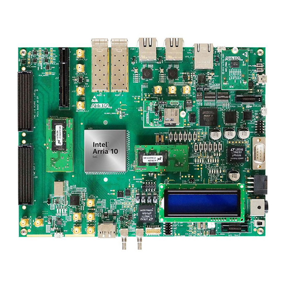
2016.03.01 Board Component Blocks The development board features the following major component blocks: • Arria 10 Soc (10AS066N3F40E2SGE2) in a 1517-pin FBGA (FineLine Ball-Grid Array) package • FPGA configuration circuitry • Active Serial (AS) x1 or x4 configuration (EPCQ1024L) ®... - Page 8 C port (I2C1 of shared I/O bit 12 and 13) • FPGA I/O connections: • FPGA V57.1 High Pin Count FMC slot • FPGA Altera Low Pin Count FMC slot • FMC_PCIe Gen2 x8 EP cable • FPGA PCIe GEN1/2/3 x8 RC slot •...
-
Page 9: Recommended Operating Conditions
When handling the board, it is important to observe static discharge precautions. Caution: Without proper anti-static handling, the board can be damaged. Therefore, use anti-static handling precautions when touching the board. Arria 10 SoC Development Kit Overview Altera Corporation Send Feedback... -
Page 10: Getting Started
Altera assumes no responsibility or liability arising out of the application or use of any information, product, or service described herein except as expressly agreed to in writing by Altera. Altera customers are advised to obtain the latest version of device specifications before relying on any published information and before placing orders for products or services. - Page 11 Included in the Quartus Prime Pro Edition software are the Quartus Prime software, the Nios II EDS, and the MegaCore IP Library. To install the Altera development tools, download the Quartus Prime Pro Edition Software from the Quartus Prime Pro Edition page in the Download Center of the Altera website. Related Information...
-
Page 12: Activating Your License
Altera SoCs. For more information, refer to the ARM Development Studio 5 (DS-5) Altera Edition Toolkit. For the steps to install the SoC EDS Tool Suite, refer to the Altera SoC Embedded Design Suite User Guide. Related Information •... -
Page 13: Development Kit Installer
1. Download the Arria 10 FPGA Development Kit installer from the Arria 10 FPGA Development Kit page of the Altera website. Alternatively, you can request a development kit DVD from the Altera Kit Installations DVD Request Form page of the Altera website. -
Page 14: Installing The Usb-Blaster Driver
Installation instructions for the on-board USB-Blaster II driver for your operating system are available on the Altera website. On the Altera Programming Cable Driver Information page of the Altera website, locate the table entry for your configuration and click the link to access the instructions. -
Page 15: Development Board Setup
Altera assumes no responsibility or liability arising out of the application or use of any information, product, or service described herein except as expressly agreed to in writing by Altera. Altera customers are advised to obtain the latest version of device specifications before relying on any published information and before placing orders for products or services. -
Page 16: Default Switch And Jumper Settings
1. Set the DIP switch bank (SW1) to match "SW1 DIP Switch Settings" table and the "Default Switch and Jumper Settings" figure. Note: In the following table, ON indicates the switch is to the upper position according to the board orientation as shown in the "Default Switch and Jumper Settings" figure. Development Board Setup Altera Corporation Send Feedback... - Page 17 Switch 4.4 has the following options: • ON (Up) = MSEL2 is 1 • OFF (Down) = MSEL2 is 0 Table 3-3: MSEL Settings for each Configuration Scheme of Arria 10 SoC Devices Configuration Power-On Reset (POR Valid MSEL [2:0]...
- Page 18 OFF- FMCB JTAG Enable PCIe ON- PCIe JTAG Bypass OFF- PCIe JTAG Enable MSTR0 On-Board USB Blaster II JTAG Master MSTR1 On-Board USB Blaster II JTAG Master MSTR2 On-Board USB Blaster II JTAG Master Development Board Setup Altera Corporation Send Feedback...
- Page 19 SHORT upper 2 pins Related Information Board Settings DIP Switch on page 5-19 The directions of these pins are in reference to the board arrangement as in the "Default Switch and Jumper Settings" figure. Development Board Setup Altera Corporation Send Feedback...
-
Page 20: Board Test System
Altera assumes no responsibility or liability arising out of the application or use of any information, product, or service described herein except as expressly agreed to in writing by Altera. Altera customers are advised to obtain the latest version of device specifications before relying on any published information and before placing orders for products or services. -
Page 21: Preparing The Board
The application cannot run correctly unless Quartus Prime 15.1 Programmer is opened. Note: Do not use the Auto Detect function in the Quatus Prime Programmer. It may cause the board power to reset. Board Test System Altera Corporation Send Feedback... -
Page 22: Running The Board Test System
BoardTestSystem.exe On Windows, you can also run the BTS from the Start > All Programs > Altera menu. The BTS relies on the Quartus Prime software's specific library. Before running the BTS, open the Quartus Prime software to automatically set the environment variable . -
Page 23: Using The Board Test System
1. On the Configure menu, click the configure command that corresponds to the functionality you wish to test. 2. In the dialog box that appears, click Configure to download the corresponding design to the FPGA. Figure 4-3: Programmer Dialog Window Board Test System Altera Corporation Send Feedback... -
Page 24: The System Info Tab
Board Name Indicates the official name of the board, given by the Board Test System. Board P/N Indicates the part number of the board. Serial Number Indicates the serial number of the board. Board Test System Altera Corporation Send Feedback... - Page 25 Indicates the version of the Board Test System currently running on the board. JTAG Chain Shows all the devices currently in the JTAG chain. Qsys Memory Map Shows the memory map of the Qsys system on your board. Board Test System Altera Corporation Send Feedback...
-
Page 26: The Gpio Tab
Displays the current state of the user LEDs for the FPGA. To toggle the board LEDs, click one of the LED [ 0 to 3] buttons to toggle the 4 green LEDs, or click the All button. Board Test System Altera Corporation Send Feedback...
Need help?
Do you have a question about the Arria 10 SoC and is the answer not in the manual?
Questions and answers