Table of Contents
Advertisement
Quick Links
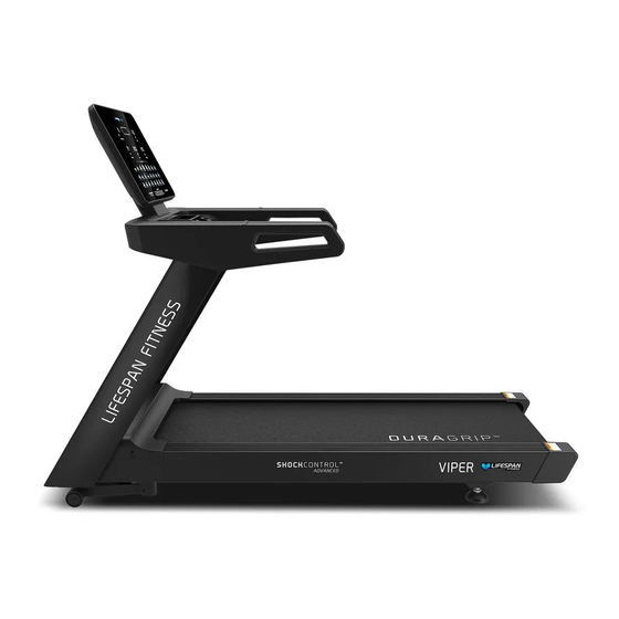
Viper M4 Treadmill
USER MANUAL
Product may vary slightly from the item pictured due to model upgrades.
Read all instructions carefully before using this product.
Retain this owner's manual for future reference.
NOTE:
This manual may be subject to updates or changes. Up to date manuals are available through our
website at www.lifespanfitness.com.au
Advertisement
Table of Contents

Related Manuals for LifeSpan Viper M4


Summary of Contents for LifeSpan Viper M4
- Page 1 Viper M4 Treadmill USER MANUAL Product may vary slightly from the item pictured due to model upgrades. Read all instructions carefully before using this product. Retain this owner’s manual for future reference. NOTE: This manual may be subject to updates or changes. Up to date manuals are available through our...
-
Page 2: Table Of Contents
TABLE OF CONTENTS Important Safety Instructions ....... 03 II. Important Electrical Information ......05 III. -
Page 3: Important Safety Instructions
I. IMPORTANT SAFETY INSTRUCTIONS WARNING: Read all instructions before using this treadmill. It is important your treadmill receives regular maintenance to prolong its useful life. Failing to regularly maintain your treadmill may void your warranty. DANGER To reduce the risk of electric shock disconnect your treadmill from the electrical outlet prior to cleaning and/or service work. - Page 4 • The treadmill is intended for in-home use only and is not suitable for commercial environments. • The pulse sensors are not medical devices. Various factors, including the user’s movement, may affect the accuracy of heart rate readings. The pulse sensors are intended only as exercise aids in determining heart rate trends in general.
-
Page 5: Important Electrical Information
II. IMPORTANT ELECTRICAL INFORMATION WARNING! • Route the power cord away from any moving part of the treadmill including the elevation mechanism and transport wheels. • NEVER remove any cover without first disconnecting AC power. • NEVER expose this treadmill to rain or moisture. This treadmill is not designed for use outdoors, near a pool, or in any other high humidity environment. -
Page 6: Important Operating Instructions
III. IMPORTANT OPERATING INSTRUCTIONS • Understand that changes in speed and incline do not occur immediately. Set your desired speed on the computer console and release the adjustment key. The computer will obey the command gradually. • Use caution while participating in other activities while walking on your treadmill, such as watching television, reading, etc. -
Page 7: Assembly Instructions
IV. ASSEMBLY INSTRUCTIONS Description Main frame Console frame Left upright tube Right upright t ube Power wire Console B06 S=13, 14, 15 (1x) B07 5# (1x) B08 6# (1x) B11 8# (1x) D06 M10*20 (12x) ф ф ф ф 10 (12x) 10 (12x) D10 M8 (4x) 8 (4x) - Page 8 STEP 1 1. Open and remove parts from the carton. Make sure you have enough space to assemble and the floor is flat. | ASSEMBLY INSTRUCTIONS...
- Page 9 B06 S=13, 14, 15 (1x) B07 5# (1x) STEP 2 1. Pull out the Console screw cover (No. C22) from the Console base (No. B). 2. Loosen the Bolt (No. D12) on the Motor top cover (No. C03) by using Wrench w/ screw driver (No.
- Page 10 B11 8# (1x) D06 M10*20 (6x) ф ф 10 (6x) 10 (6x) STEP 3 1. Connect the wires (E08 & E09) from Right upright tube (No. D) and Main base (No. A). 2. Support the Left & Righ t Upright Tubes (No.C & No.D) with your hands to prevent them from falling.
- Page 11 B06 S=13, 14, 15 (1x) B07 5# (1x) D12 M5*12 (3x) D17 M6*10 (2x) STEP 4 1. Attach the Bolt (No. D12) to the Motor top cover (No. C03) by using Wrench w/screwdriver (No. B06). 2. Attach the Bolt (No. D17) to the Motor top cover (No. C03) by using 5# Allen wrench (No. B07) using 6 x Bolts (No.
- Page 12 B11 8# (1x) D06 M10*20 (6x) ф ф 10 (6x) 10 (6x) STEP 5 1. Connect the wires (E07 & E08) from Right upright tube (No. D) and Console base (No. B). 2. Attach the Left & Right Upright Tubes (No. C & No. D) to the Console base (No. B) by using 6 x Bolts (No.
- Page 13 B08 6# (1x) D10 M8 *15 (4x) ф ф 8 (4x) 8 (4x) STEP 6 1. Attach the Console (No. E) to the Console base (No. B) by using 4 x Bolts (No. D10), 4 x Washers (No. D23) and 4 x Washers (No. D22). Secure by using 6# Allen Wrench (No. B08). ASSEMBLY INSTRUCTIONS |...
- Page 14 STEP 7 1. Connect the wire (No. E04 & No. E05 & No. E06 & No. E07 & No. E10 & No. E11 & No. E13 & No. E14). Attach the Console screw cover (No. C22) from the Console base (No. B). The assembly is complete! | ASSEMBLY INSTRUCTIONS...
-
Page 15: Transportation Wheels
V. TRANSPORTATION WHEELS Move the treadmill by holding the end of the treadmill frame base and tilt it onto the wheels. You can now move it to your desired location. Caution: Treadmill is heavy and will require a fit and capable adult to move or 2x adults if required. FOLDING INSTRUCTIONS |... -
Page 16: Important Electrical Information
VI. IMPORTANT ELECTRICAL INFORMATION WARNING: This treadmill requires a right power source in order to properly operate. For your safety, as well as the safety of others, please verify that the power source is correct before plugging the equipment. Any incorrect power source could cause significant damage to the equipment and or user. -
Page 17: Operation Guide
VII. OPERATION GUIDE BUTTON FUNCTIONS 1. INCLINE - : Press this button to reduce the incline 2. INCLINE +: Press this button to increase the incline 3. INSTANT INCLINE: Press 3 6 9 to choos e incline quickly. 4. START: Press this button to start the machine. 5. - Page 18 COMPUTER FUNCTIONS: 1. INCLINE: Display current incline. Press INCLINE+/ to adjust the incline of the machine. 2. SPEED: Display current speed. Press SPEED+/ to adjust the speed of the machine. 3. CALORIES: Display the calories has consume. 4. TIME: Display the time has run. 5.
- Page 19 TIME INTERVAL= SETTING TIME/10 PROG/TIME SPEED INCLINE SPEED INCLINE SPEED INCLINE SPEED INCLINE SPEED INCLINE SPEED INCLINE SPEED INCLINE SPEED INCLINE SPEED INCLINE SPEED INCLINE SPEED INCLINE SPEED INCLINE SPEED INCLINE SPEED INCLINE SPEED INCLINE SPEED INCLINE SPEED INCLINE SPEED INCLINE OPERATION GUIDE |...
- Page 20 TIME INTERVAL= SETTING TIME/10 PROG/TIME SPEED 3P19 INCLINE SPEED INCLINE SPEED INCLINE SPEED INCLINE SPEED INCLINE SPEED INCLINE 7.3 Set of 3 user programs: From standby mode, press Mode button, console will show 3 user programs, select between 3 user programs. - Press SPEED+/ or INCLINE to set the workout target value.
- Page 21 GENDER 01 Male 02 Female 10-99 100-200CM Height Weight 20-150KG ≤19 Under weight =(20-25) Normal weight =(26-29) Overweight ≥ 30 Obesity LUBRICATION REMIND FUNCTION This machine has lubrication remind function. After every total running distance of 300km (188miles), your treadmill need s to be maintained with oil. The system will remind with sound for every 10 seconds, and window will show "OIL".
-
Page 22: Exercise Guide
VIII. EXERCISE GUIDE PLEASE NOTE: Before beginning any exercise program, consult your physician. This is important especially if you are over the age of 45 or individuals with pre-existing health problems. The pulse sensors are not medical devices. Various factors, including the user’s movement, may affect the accuracy of heart rate readings. - Page 23 COOL DOWN Finish each workout with a light jog or walk for at least 1 minute. Then complete 5 to 10 minutes of stretching to cool down. This will increase the flexibility of your muscles and will help prevent post- exercise problems.
-
Page 24: Maintenance & Care
IX. MAINTENANCE & CARE General cleaning will help prolong the life and performance of your treadmill. Keep the unit clean and maintained by dusting the components on a regular basis. Clean both sides of the running belt to prevent dust from accumulating underneath the belt . Keep your running shoes clean so that dirt from your shoes does not wear out the running board and belt. - Page 25 2. The moving parts should turn freely and quietly. Abnormality of moving parts will affect the safety of the equipment. Inspect and tighten bolts regularly. 3. To better maintain the treadmill and prolong its lifespan, it is suggested that maintenance be done on a regular basis.
- Page 26 5. CENTERING THE RUNNING BELT Place the treadmill on level ground and set it at 6-8kph to check if the Running Belt drifts. 1. If the Running Belt moves to the right, turn the adjusting bolt on the right side ¼ turn clockwise, then turn the left adjustment bolt ¼...
- Page 27 Some treadmills that have longer belts may give different measurements for correct belt tightness. Simply, if the belt begins to slip during use, this is an indication that the belt still needs tightening. Video Tutorial Available at: http://youtu.be/vllsamTSvvA Lifespan Fitness YouTube Channel: http://www.youtube.com/user/treadmillsvideos MAINTENANCE INSTRUCTIONS |...
-
Page 28: Exploded Diagram
X. EXPLODED DIAGRAM | EXPLODED DIAGRAM... - Page 29 EXPLODED DIAGRAM |...
-
Page 30: Parts List
XI. PARTS LIST Description Specs Description Specs Main frame Plastic side rail gasket Incline bracket Plastic gasket Console base bracket Console top cover Panel connecting bracket Emergency button Left upright tube Button holder Right upright tube Console bottom cover Front roller Console screw cover Back roller Console support top cover... - Page 31 Description Specs Description Specs Spring washer Microswitch Bolt M5*16 Switch top signal wire Bolt M5*12 Switch bottom signal wire Spring washer 5/65Mn Running board Lock washer DC motor Bolt M8*40 Incline motor Screw ST4.2*20 Magnetic ring Console Magnetic core Control board Power wire Touch button board AC signal wire...
-
Page 32: Troubleshooting
XII. TROUBLESHOOTING PROBLEM POSSIBLE CAUSE SUGGESTED ACTION Not plugged in Plug cord into outlet Treadmill will not start Safety Key not inserted Insert Safety Key Running belt tension not Running belt not Tighten the adjustment bolts on the left and correct on the left or right centered right side of the rear roller. - Page 33 Check whether the power wire is dropped Hardware error Check the control board, replace if damaged. Re-connect or replace the wire for the incline Incline failure motor. Replace the incline motor witha new one. Check if the incline wire is connected properly. Calibration failure Recalibrate after connecting the ascending wire.
-
Page 34: Warranty
Any claim against this warranty must be made through your original place of purchase. Proof of purchase is required before a warranty claim may be processed. If you have purchased this product from the Official Lifespan Fitness website, please visit https://lifespanfitness.com.au/warranty-form For support outside of warranty, if you wish to purchase replacement parts or request a repair or service, please visit https://lifespanfitness.com.au/warranty-form and fill in our Repair/Service... -
Page 35: Hand Pulse Technology
XIV. HAND PULSE TECHNOLOGY This product comes equipped with hand pulse sensors which are used to pick up tiny EKG/ECG signals that run through the body when your heart beats. These electrical EKG/ECG signals are very small and that they must be amplified 1000 times to make the signal useful for the computer to display your pulse. - Page 36 WWW.L IF ESPAN F ITNE S S . COM . A U...
Need help?
Do you have a question about the Viper M4 and is the answer not in the manual?
Questions and answers