Table of Contents
Advertisement
Quick Links
Product may vary slightly from the item pictured due to model upgrades.
Read all instructions carefully before using this product.
Retain this owner's manual for future reference.
NOTE:
This manual may be subject to updates or changes. Up to date manuals are available through our
website at www.lifespanfitness.com.au
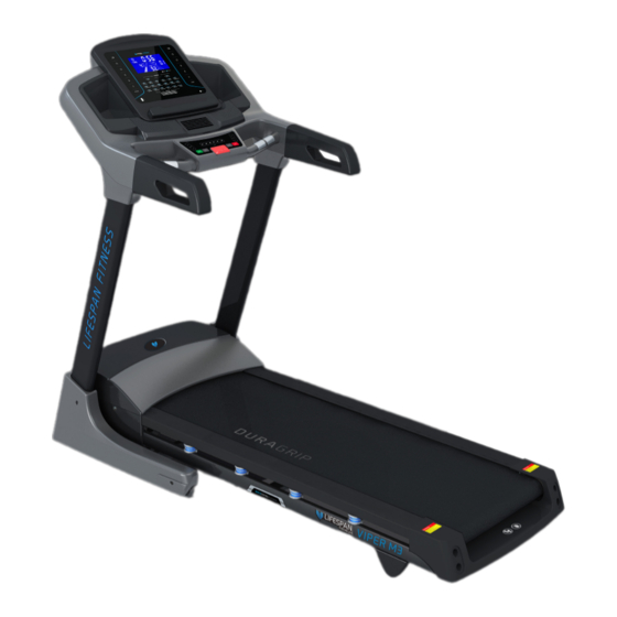
Viper M3
Treadmill
USER MANUAL
Advertisement
Table of Contents

Related Manuals for LifeSpan Viper M3


Summary of Contents for LifeSpan Viper M3
- Page 1 Viper M3 Treadmill USER MANUAL Product may vary slightly from the item pictured due to model upgrades. Read all instructions carefully before using this product. Retain this owner’s manual for future reference. NOTE: This manual may be subject to updates or changes. Up to date manuals are available through our...
-
Page 2: Table Of Contents
TABLE OF CONTENTS Important Safety Instructions ....... 03 II. Important Electrical Information ......05 III. -
Page 3: Important Safety Instructions
I. IMPORTANT SAFETY INSTRUCTIONS WARNING: Read all instructions before using this treadmill. It is important your treadmill receives regular maintenance to prolong its useful life. Failing to regularly maintain your treadmill may void your warranty. DANGER To reduce the risk of electric shock disconnect your treadmill from the electrical outlet prior to cleaning and/or service work. - Page 4 • The treadmill is intended for in-home use only and is not suitable for commercial environments. • The pulse sensors are not medical devices. Various factors, including the user’s movement, may affect the accuracy of heart rate readings. The pulse sensors are intended only as exercise aids in determining heart rate trends in general.
-
Page 5: Important Electrical Information
II. IMPORTANT ELECTRICAL INFORMATION WARNING! • Route the power cord away from any moving part of the treadmill including the elevation mechanism and transport wheels. • NEVER remove any cover without first disconnecting AC power. • NEVER expose this treadmill to rain or moisture. This treadmill is not designed for use outdoors, near a pool, or in any other high humidity environment. -
Page 6: Important Operating Instructions
III. IMPORTANT OPERATING INSTRUCTIONS • Understand that changes in speed and incline do not occur immediately. Set your desired speed on the computer console and release the adjustment key. The computer will obey the command gradually. • Use caution while participating in other activities while walking on your treadmill, such as watching television, reading, etc. -
Page 7: Assembly Instructions
IV. ASSEMBLY INSTRUCTIONS Description Description Main frame Bolt 8*20 Allen Wrench S=13\14\15mm Bolt M8*55 5#Allen Wrench Lock washer 6#Allen Wrench Screw ST4.2*19 Left base cover Standard Power Line Right base cover Mp3 Wire Safety key ASSEMBLY TOOLS: NOTICE: #5 Allen Wrench 5mm: 1pc Do not connect power until after assembly is #6 Allen wrench 6mm: 1pc completed. - Page 8 STEP 1 STEP 2 1. Open the carton. 1. Erect the upright tubes in the direction of the 2. Extract the parts listed above. arrows. 3. Place the Main Frame onto level ground. NOTE: Take care not to damage the upright covers (23, 24) or the wires inside the uprights.
- Page 9 86 70 STEP 3 STEP 4 1. Attach the Right Upright to the base frame 1. Attach the computer frame onto the right (2) using 5# Allen wrench (13), Bolt upright with the 5# Allen wrench (13), M8*20 M8*55(70), Bolt M8*20 (67) and 2 x Lock bolt (67) and lock washer (86).
- Page 10 STEP 5 STEP 6 1. Attach the right upright cover to the 1. Connect the power cord (53) onto main frame. computer bracket with screw driver (12), Bolt ST4.2*19 (75) and ST4.2*20 bolt (88). 2. Attach the base cover (31) to the base frame (2) using screw driver (12), ST4.2*20 Bolt (88) and bolt (75).
-
Page 11: Folding Instructions
Whilst supporting position (A) with our hand, gently push position (B), the marked area on the air pressure bar, with your foot.The base frame will descend automatically. (Please keep people and any pets away the machine during descent) Video Tutorial Available at: http://youtu.be/TcuPbJ7KuxQ Lifespan Fitness YouTube Channel: http://www.youtube.com/user/treadmillsvideos FOLDING INSTRUCTIONS |... -
Page 12: Operation Guide
VI. OPERATION GUIDE OVERVIEW LCD WINDOW DISPLAY 1. SPEED WINDOW: Displays speed and program 2. INCLINE WINDOW: Displays incline level 3. TIME WINDOW: Displays workout time 4. DISTANCE WINDOW: Displays workout distance 5. CALORIE WINDOW: Displays calories burn 6. PULSE WINDOW: Displays pulse (Calorie and pulse data is an estimate intended for reference only. - Page 13 BUTTON FUNCTIONS: 1. "PROG": When the treadmill is in standby mode, this button cycles through: a. "HRC" – heart rate control programs b. "P1-P40" – built in programs c. "U1-U3" – user defined programs d. "FAT" – body fat testing mode 2.
- Page 14 Time Setting Range 99:59 min Distance Setting Range 0.5-99.9 km Calorie Setting Range 10.0 – 999.0 calories PRESET PROGRAMS: Press the program button; programs from P1 to P40 are built-in programs. The time window displays the default value of TIME. When flashing, press the SPEED +/- and INCLINE +/- buttons to adjust to your desired time.
- Page 15 HEART RATE CONTROL (HRC) PROGRAMS: DEFAULT is the default heart rate display parameter values (Default display) Program Number Functions Incline only Speed only Speed and incline • HRC programs have a maximum duration of 22 minutes. • In standby mode, press the "Program" key until the DISTANCE window displays HP1, HP2 or HP3. When in the HP1/HP2/HP3 display interface, press the start key to select a HRC program.
- Page 16 Scenario Program Number Result Incline will increase by 1 level every 10 seconds, until the incline limit or the target heart rate is reached. (speed is controlled by the user) Speed will increase by 0.5km/h every 10 seconds, until the speed limit or the target heart rate is Actual heart rate is less reached.
- Page 17 BODY FAT TESTER: Press "PROGRAM" until the window displays "FAT". Press "MODE" to select parameters after entering data (F1 = "SEX", F2 = "AGE", F3 = "HEIGHT", F4 = "WEIGHT"). Use "SPEED+/-" to set data. After entering all data the window will display "F5". Place both hands on the hand sensors for 5 seconds, and the window will display your body fat data.
- Page 18 POWER SAVING MODE: The treadmill automatically enters sleep mode after 30 minutes of inactivity. Press any key on the display to wake the treadmill. SAFETY KEY FUNCTION: The machine will not function without the safety key being correctly attached. Pulling out the safety will set the display into "off"...
-
Page 19: Exercise Guide
VII. EXERCISE GUIDE PLEASE NOTE: Before beginning any exercise program, consult your physician. This is important especially if you are over the age of 45 or individuals with pre-existing health problems. The pulse sensors are not medical devices. Various factors, including the user’s movement, may affect the accuracy of heart rate readings. - Page 20 COOL DOWN Finish each workout with a light jog or walk for at least 1 minute. Then complete 5 to 10 minutes of stretching to cool down. This will increase the flexibility of your muscles and will help prevent post- exercise problems.
-
Page 21: Maintenance Instructions
VIII. MAINTENANCE INSTRUCTIONS Reasonable cleaning/lubricating should be made to extend the life time of this unit. Performance is maximized when the belt and mat are kept as clean as possible. WARNING: • The mat/deck friction may lay a major role in the function and life of your treadmill and that is why we recommend you constantly lubricate this friction point to prolong the useful life of your treadmill. - Page 22 Running Belt Board Video Tutorial Available at: http://youtu.be/cP9NtFHfWlc Lifespan Fitness YouTube Channel: http://www.youtube.com/user/treadmillsvideos 4. HOW TO CHECK THE RUNNING MAT FOR PROPER LUBRICATION 1. Disconnect the main power supply. 2. Fold the treadmill up into the storage position. 3. Feel the underside surface of the running mat.
- Page 23 5. ADJUSTING THE RUNNING BELT Place treadmill on a level surface. Run treadmill at approximately 4km/h, checking the running condition. If the belt has drifted to the right: Whilst the If the belt has drifted to the left: Whilst the treadmill is running at 4km/h, carefully turn treadmill is running at 4km/h, carefully turn the right adjusting bolt 1/4 turn clockwise.
- Page 24 Some treadmills that have longer belts may give different measurements for correct belt tightness. Simply, if the belt begins to slip during use, this is an indication that the belt still needs tightening. Video Tutorial Available at: http://youtu.be/vllsamTSvvA Lifespan Fitness YouTube Channel: http://www.youtube.com/user/treadmillsvideos | MAINTENANCE INSTRUCTIONS...
-
Page 25: Replacing Motor Brushes
IX. REPLACING MOTOR BRUSHES After extended use, the motor brushes in your treadmill motor will wear down, and this can lead to motor failure. It is important that you maintain your motor by replacing the brushes on either side of the motor when they are worn down. - Page 26 4b. Some treadmill motors may use a push 4c. Remove the clip, noting the direction in clip instead. In this case, gently push the which it was originally placed, and put it clip inwards and then up to release it from safely aside.
- Page 27 9a. Release the clip back into its position. 9b. If your motor uses a push clip, replace the push clip by pushing it inwards and then down so that it engages the catch. 10. Check that the motor brush is held firmly 11.
-
Page 28: Exploded Diagram
X. EXPLODED DIAGRAM | EXPLODED DIAGRAM... -
Page 29: Parts List
XI. PARTS LIST Description Specs Description Specs Main Frame Hand Pulse Base Frame Transport Wheel Left Upright Face Panel Right Upright Drive Belt Computer Bracket Motor Bottom Cover Incline Bracket Left Handle Bar Motor Bracket Right Handle Bar Rotating Pipe Incline Motor Cylinder DC Motor... - Page 30 Description Specs Description Specs Bolt M8*20 Lock Washer Bolt M10*65 Bolt ST4.2*19 Bolt M4*50 Bolt ST4.2*20 Bolt M8*55 Foot Pad Bolt M10*42 Bolt M10*60 iPad Rack Bolt M8*40 Fan Blade Bolt M6*40 Filter Bolt ST4.2*19 Inductor Lock Nut CE Fix Board Bolt ST4.2*12 Wind Scooper...
-
Page 31: Troubleshooting
XII. TROUBLESHOOTING ERROR/CODE DESCRIPTION POSSIBLE SOLUTIONS 1. Please check if the overload protect jump, if it has, please press it, let it continue operation. 2. Ensure the wires of the power switch, overload protection, control board and the transformer are connected correctly. Computer not 3. - Page 32 1. Ensure power is correct, if not, use correct power to test. Burst Clash 2. Check if the bottom control boards is burnt out, if burnt out replace it and then reconnect the motor wire. Control Board Error 1. Check and replace controller. Control Board Error 1.
-
Page 33: Warranty
Any claim against this warranty must be made through your original place of purchase. Proof of purchase is required before a warranty claim may be processed. If you have purchased this product from the Official Lifespan Fitness website, please visit https://lifespanfitness.com.au/warranty-form For support outside of warranty, if you wish to purchase replacement parts or request a repair or service, please visit https://lifespanfitness.com.au/warranty-form and fill in our Repair/Service... - Page 36 WWW.LIFESPA NF ITN ES S.COM.AU...
Need help?
Do you have a question about the Viper M3 and is the answer not in the manual?
Questions and answers