Table of Contents
Advertisement
Quick Links
Advertisement
Table of Contents

Subscribe to Our Youtube Channel
Related Manuals for Digitus DS-55508


Summary of Contents for Digitus DS-55508
- Page 1 4K HDBaseT™ HDMI Extender Set, 150 m Manual DS-55508...
-
Page 2: Table Of Contents
Table of Contents 1. Introduction ................2 2. Main Features ................. 3 3. Package Contents ..............3 4. Specification ................3 5. Operating Controls and Functions ..........5 5.1 Transmitter Panel..............5 5.2 Receiver Panel ................ 7 5.3 IR Pin Definition ..............9 6. -
Page 3: Main Features
2. Main Features Supports HDBaseT™ 1.0 via CAT6A/7/8 cable up to 100 m • Supports 4K2K/60Hz (4:4:4) • Maximum transmission distance (UHD 4K2K): 120 m • Maximum transmission distance (Full HD 1080p): 150 m • • Video bandwidth: 18 Gbps •... - Page 4 Connections • 1x HDMI input (4K/60Hz) – Connection signal source • 1x RJ45 (HDBaseT™) output – Connection CAT transmission cable • 1x HDMI loop-out / output – Connection of local monitor (source device) • 1x IR input to receive remote control signals Transmitter •...
-
Page 5: Operating Controls And Functions
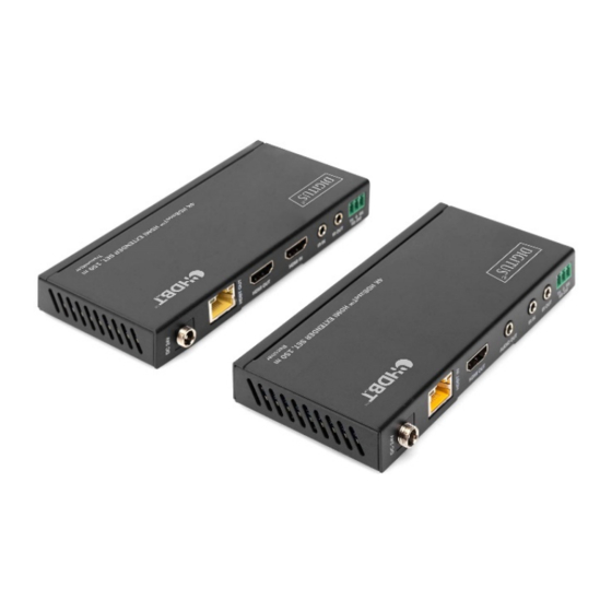
Mechanical Housing Metal Color Black Dimensions L 14 x W 6.5 x H 1.8 cm (1 unit) Weight Transmitter: 160g, Receiver: 155g Power approx. 9.36 W Consumption Operating 0 - 40°C Temperature Resolution / 4K60 - 4K30 - 1080P60 - Cable Length Feet / Meters Feet / Meters... - Page 6 Name Function description Red LED indicates that the transmitter is Power LED powered on SERVICE port Firmware update port DC 24V/1A power supply input port. Note that the extender supports PoC function, it DC 24V means that either transmitter or receiver is powered on by 24V/1A power adapter, the other one doesn’t need power supply RJ45 connector for connecting the HDBT...
-
Page 7: Receiver Panel
The RS-232 command will be pass- through from transmitter to receiver or from receiver to transmitter 5.2 Receiver Panel Name Function description Red LED indicates that the receiver is Power LED powered on SERVICE Firmware update port port DC 24V/1A power supply input port. Note that the extender supports PoC function, it DC 24V means that either transmitter or receiver is... - Page 8 Signal • Flashing: Transmitter and Receiver are in Indicator poor connection status lamp • Dark: Transmitter and Receiver are not connected • Illuminating: HDMI signal with HDCP Data Signal • Flashing: HDMI signal without HDCP Indicator • Dark: No HDMI signal HDMI OUT HDMI output for display AUDIO...
-
Page 9: Ir Pin Definition
5.3 IR Pin Definition IR Receiver and Blaster pin’s definition is as below: IR RECEIVER IR BLASTER IR Blaster IR Blaster Signal Power IR Receiver IR Signal Power Grounding... - Page 10 The following is IR system diagram about IR cable use method. Transmitter TV remote IR Blaster cable IR Receiver cable CAT 5e/6 cable DVD remote Receiver Note: When the angle between the IR receiver and the remote control is ± 45°, the transmission distance is 0-5 meters; when the angle between the IR receiver and the remote control is ±...
-
Page 11: Application Example
6. Application Example... - Page 12 Transmitter Controller Receiver UHDTV Power Supply IR Blaster CAT 5e/6 cable IR Receiver DVD or Blu-ray Player 2.0 Speaker Disclaimer The terms HDMI and HDMI High-Definition Multimedia interface, and the HDMI Logo are trademarks or registered trademarks of HDMI Licensing LLC in the United States and other countries. HDBaseT™...
Need help?
Do you have a question about the DS-55508 and is the answer not in the manual?
Questions and answers