
Related Manuals for AERMEC WRC40


Summary of Contents for AERMEC WRC40
- Page 1 2 0 . 1 1 - 5 3 8 5 4 8 3 _ 0 0 T r a n s l a t i o n f r o m o r i g i n a l W R C 4 0 U s e r m a n u a l ■...
-
Page 3: Table Of Contents
SUMMARY ELECTRICAL DEVICES WARNINGS ...................................5 WIRED PANEL ..........................................6 INSTALLING THE WIRED PANEL ....................................7 USER INTERFACE ...........................................9 USER INTERFACE (DISPLAY) ....................................10 FUNCTIONS OF THE WIRED PANEL ..................................11 SWITCHING THE UNIT ON / OFF ................................... 11 SELECTING AN OPERATING MODE ..................................11 SETTING THE OPERATING SETPOINT .................................. - Page 4 Dear customer, Thank you for choosing an AERMEC product. It is the fruit of many years of experience and special design studies and has been made of the highest grade materials and with cutting edge technology. In addition, all our products bear the EC mark indicating that they meet the requirements of the European Machine Directive regarding safety.
-
Page 5: Electrical Devices Warnings
• The incorrect installation or assembly of the may b e serious depending on the circumstances. device could cause electrocution, short-circuits, • Aermec will in no case be liable for any damages losses and fire accidents. to property and/or persons caused by improper •... -
Page 6: Wired Panel
WIRED PANEL The wired panel (accessory) allows the rapid setting of the unit operating parameters and their display. The panel can memorise all the settings, and use them when it starts up again automatically after a power failure. The user interface has an LCD display with simple icons giving information and showing the available functions on the units;... -
Page 7: Installing The Wired Panel
INSTALLING THE WIRED PANEL DIMENSIONS OF THE WIRED PANEL: 106,5 [mm]... - Page 8 Notes for installing the wired panel. It’s important to respect the following indications: 1. Before beginning, make sure the indoor unit is WARNING: not electrically powered. • To avoid electromagnetic disturbance, 2. Before installing the panel, pass the serial remember to keep the serial communication communication cable through the specific line separate from the unit power line trunking, as far as the flush-mounting box.
-
Page 9: User Interface
USER INTERFACE Icon Function Sets fan speed Used to increase or decrease the selected data item, or move to the previous/next item Used to switch the indoor unit on or off, or to return to the previous level when scrolling through the menus Sets the operating mode for the unit Used to activate or deactivate a function, or to move from one... -
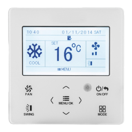
Page 10: User Interface (Display)
USER INTERFACE (DISPLAY) Icon Function Indicates the current fan speed setting Indicates that the settings are saved on the wired panel memory The energy-saving function is active The prolonged ventilation function is active (X-FAN) The air filter in the indoor unit must be cleaned Indicates any hourly settings that may be active... -
Page 11: Functions Of The Wired Panel
FUNCTIONS OF THE WIRED PANEL SWITCHING THE UNIT ON / OFF Switching the unit on/off To switch the indoor unit managed via the wired panel on or off, press the key ON/OFF MENU/OK MODE SWING SELECTING AN OPERATING MODE Selecting an operating mode ON/OFF To modify the operating mode of the indoor unit MENU/OK... -
Page 12: Setting The Operating Setpoint
SETTING THE OPERATING SETPOINT All the operating modes (except the automatic one) Operating set point require an room air temperature value to control to: this is called the operating set-point. If the unit is on (and the automatic mode is not selected), just press the arrow keys to decrease or increase the operating setting by 1 °C. -
Page 13: Setting The Vertical Motorised Discharge Fin (Up&Down Swing)
SETTING THE VERTICAL MOTORISED DISCHARGE FIN (UP&DOWN SWING) ON/OFF MENU/OK Setting the swing If the unit is on, while pressing the button MODE SWING activates the swing of the motorized supply air fin (UP&DOWN). The fin allows to change the air flow in the room depending on the set position;... -
Page 14: Setting The System Functions
SETTING THE SYSTEM FUNCTIONS ON/OFF Accessing the settings menu Press the button to access the main menu MENU/OK where the functions are grouped into sub-menus, MODE each represented by a different icon. SWING To access timer programming, proceed as follows: ON/OFF •... - Page 15 HEALTH - AIR PURIFIER COLD PLASMA SAVE The HEALTH function enable or disable the air The SAVE function is used to set a minimum purifier Cold Plasma function capable of reducing temperature limit for cooling and dehumidifica- pollutants breaking down their molecules using tion modes, and a maximum temperature limit for electric discharges, causing the splitting of the heating mode.
-
Page 16: Independent Swing Of The Motorised Delivery Fins
QUIET FUNCTION INDEPENDENT SWING OF THE MOTORISED DELIVERY FINS The QUIET function (available in cooling, heating and automatic mode) activates or deactivates quiet operation to reduce the noise level of the indoor By activating the INDEPENDENT SWING function, unit and deactivate acoustic feedback. the four air delivery outlets of the unit can be inde- pendently controlled. -
Page 17: Controlling The Opening Of The Front Panel Of The Unit
CONTROLLING THE OPENING OF THE FRONT PANEL OF THE UNIT With this function, the front panel of the unit can be automatically opened to make it easier to clean the filter. With the unit switched on, enter the sub-menu of the function and press the button to control the up and down movement of the panel. -
Page 18: Units Status And Alarm Log
UNITS STATUS AND ALARM LOG From the main control panel menu, select the ON/OFF Viewing the unit status and the alarm log SEARCH icon and then press to access the MENU/OK required menu. Use the button to select the item you MODE ON/OFF SWING... -
Page 19: Setting Or Deleting A Timed Switch-On Or Switch-Off (Timer On/Timer Off)
SETTING OR DELETING A TIMED SWITCH- Timer programming ON OR SWITCH-OFF (TIMER ON/TIMER OFF) From the main menu of the control panel, select the ON/OFF TIMER icon and then press to access the MENU/OK required menu. Use the button to select the item you MODE ON/OFF SWING... -
Page 20: Daily Timer - Daily Timer Programming
DAILY TIMER - DAILY TIMER PROGRAMMING With daily timed programming, up to 8 actions can Daily timer programming be programmed (timed switch-on or switch-off operations) over a 24-hour period, thereby creating daily time bands. To set daily timed programming, enter the DAILY ON/OFF ON/OFF menu and use the... -
Page 21: Weekly Timer - Weekly Timer Programming
WEEKLY TIMER - WEEKLY TIMER PROGRAMMING Weekly timer programming allows up to 8 actions Weekly timer programming to be programmed (switch-on or switch-off operations) over a 24-hour period, thereby creating daily time bands for each day of the week. To set weekly timed programming, enter the ON/OFF ON/OFF WEEKLY menu and use the... -
Page 22: Two Week Timer - Fortnightly Timed Programming
TWO WEEK TIMER - FORTNIGHTLY TIMED PROGRAMMING With fortnightly timed programming, up to 8 Fortnightly timer programming actions can be programmed (timed switch-on or switch-off operations) over a 24-hour period, thereby creating daily time bands for each day of the two weeks. To set fortnightly timed programming, enter the ON/OFF ON/OFF... -
Page 23: Countdown Timer On
COUNTDOWN TIMER ON A countdown can be set for unit switch-on. Setting countdown timer ON After selecting and entering the page of the TIMER ON function, to set this system function use the button to set the required value for the selected number (the value being defined is shown in black). -
Page 24: Set Clock Of The System
SET CLOCK OF THE SYSTEM From the main menu of the control panel, select the ON/OFF Setting date and time CLOCK icon and then press to access the MENU/OK required menu. Use the button to select the required MODE ON/OFF SWING item, then press to confirm. -
Page 25: Setting A System Lock
SETTING A SYSTEM LOCK From the main menu of the control panel, select ON/OFF Setting the system locks LOCK icon and then press to access the MENU/OK required menu. Use the button to select the required MODE ON/OFF SWING item, then press to confirm. -
Page 26: Functions Relating To The System Menu
MODE MODE SWING SWING VALUE OF 01. Remote control address the serial address, (from 1 to 36) for the indoor unit that the WRC40 panel is ON/OFF connected to. After entering the correct values, press to save MENU/OK the data. To quit the sub-menu and return to the... -
Page 27: Setting The Ambient Probe To Be Used
To set this function, select the fan speed the one on the WRC40 remote panel (these func- mode of indoor unit label using the tions should only be used by technical assistance... -
Page 28: Setting The Ventilation Mode After The Set-Point Has Been Reached
SETTING THE VENTILATION MODE AFTER ENABLING OR DISABLING THE ECD THE SET-POINT HAS BEEN REACHED ACCESSORY This function is used to enable the ECD accessory (if This function is used to choose the type of fitted). To set this function, select the gate control ventilation control to be applied once the operating ON/OFF ON/OFF... -
Page 29: Alarm Codes
ALARM CODES Code Function Code Function High pressure Compressor test (operating frequency) Anti-freeze Compressor test (maximum High compressor delivery frequency) temperature Compressor test (intermediate Electrical overload frequency) Communication error between indoor Error generated by incorrect power and outdoor unit supply to the compressor High temperature protection Condenser malfunction on the Load error from EEPROM... - Page 32 TÉLÉCHARGER LA DERNIÈRE VERSION: TÉLÉCHARGER LA DERNIÈRE VERSION: http://www.aermec.com/qrcode.asp?q=15806 http://www.aermec.com/qrcode.asp?q=15810 http://www.aermec.com/qrcode.asp?q=15807 A E R M E C S . p . A . V i a R o m a , 9 9 6 - 3 7 0 4 0 B e v i l a c q u a ( V R ) - I t a l y T e l .
Need help?
Do you have a question about the WRC40 and is the answer not in the manual?
Questions and answers