Table of Contents
Advertisement
Advertisement
Table of Contents

Related Manuals for AERMEC MULTI CONTROL


Summary of Contents for AERMEC MULTI CONTROL
- Page 1 ELECTRONIC REGULATION BOOKLET MULTI CONTROL 4598010_00 / A5 - 1201...
-
Page 2: Table Of Contents
Index Precautions and Safety Standards ....................5 Type of systems managed by MULTI CONTROL ................. 6 Systems without additional VMF CRP modules ....................6 Systems with additional VMF CRP modules ......................7 VMF CRP 1 connections (3-way valves and probes management) ..............8 VMF CRP 2 connections (supplementary resistance management on DHW) ............ - Page 3 ALARMS MEMORY menu procedures ..................29 Alarm log display ..............................29 Description label alerts ............................30 SETUP MENU procedures ......................31 Entering password for level selection ......................... 31 Setup menu - UNIT SETUP procedures ................32 Setting working mode at HEATING (Password 101 or 303) ................32 Setting working mode at COOLING (Password 101 or 303) ................
-
Page 4: Serial Number
AERMEC S.p.A. I-37040 Bevilacqua (VR) Italy – Via Roma, 996 Tel. (+39) 0442 633111 Telefax 0442 93730 – (+39) 0442 93566 www .aermec. com - info @aermec. com MULTI CONTROL SERIAL NUMBER CE DECLARATION We, the undersigned, hereby declare under our own responsibility that the assembly in question,... -
Page 5: Precautions And Safety Standards
The appliance warranty does not cover the costs for ladders, scaffolding, or other elevation systems that may become necessary for carrying out servicing under warranty. AERMEC S.p.A. declines all responsibility for any damage due to improper use of the machine, partial or hasty reading of the information contained in this manual. -
Page 6: Type Of Systems Managed By Multi Control
- Compensation of work setting by means of outdoor air available only on units equipped with outdoor air probe. The MULTI CONTROL accessory manages the units through an RS485 serial connection; for the system to work properly, all the units must be equipped with the MODU485A accessory. -
Page 7: Systems With Additional Vmf Crp Modules
- Remote control through VMF CRP number 3. - Compensation of work setting through outdoor air available by means of KSAE accessory. The MULTI CONTROL accessory manages the units through an RS485 serial connection; for the MULTI CONTROL system to work properly, all the units must be equipped with the MODU485A accessory. -
Page 8: Vmf Crp 1 Connections (3-Way Valves And Probes Management)
• VMF CRP 1 connections (3-way valves and probes management): FUSE 1.25A 25VA 230V~50Hz V3VD (1) V3VD (2) V3VD (3) V3VD (4) MAX 230V~2A MAX 230V~2A MAX 230V~2A MAX 230V~2A 0.34 mm (AWG 22) 1.5 mm (AWG 16) MAX 30m MAX 30m VMF CRP (1) Serial Address:... -
Page 9: Vmf Crp 2 Connections (Supplementary Resistance Management On Dhw)
• VMF CRP 2 connections (supplementary resistance management on DHW): FUSE 1.25A 25VA 230V~50Hz MAX 230V~2A 1.5 mm (AWG 16) MAX 30m VMF CRP (2) Serial Address: 2 3 4 RS 485 Code Component Available as Supplementary electric resistance for DHW Component NOT supplied Resistance alarm presence output CLOSED = Alarm... -
Page 10: Vmf Crp 3 Connections (Remote Control Management)
• VMF CRP 3 connections (remote control management): FUSE 1.25A 25VA 230V~50Hz MAX 230V~2A MAX 230V~2A MAX 230V~2A MAX 230V~2A 1.5 mm (AWG 16) MAX 30m VMF CRP (3) Serial Address: 2 3 4 RS 485 Code Function Description Closed = Alarm in system General System Alarm Open = No alarm in system Closed = System ON... -
Page 11: Multi Control Serial Connection
• All of the components required for the power supply (transformers) and to position the panel inside be electric control board, ARE NOT supplied. • We recommend complying with standards in force for installation of the components outside of the MULTI CONTROL panel, entrusting installation to properly trained technical personnel. -
Page 12: Multi Control Panel User Interface
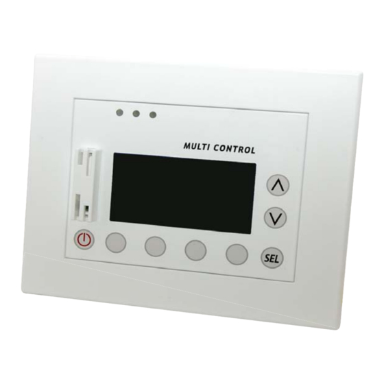
MULTI CONTROL panel user interface • Interface control keys: MULTI CONTROL accessory makes it possible to control and manage up to 4 chillers (equipped with MODUCONTROL circuit board). This accessory allows the user to manage: • Switching units ON/OFF (according to the management logic selected). -
Page 13: Structure Of Multi Control Menus
In this menu it is possible to set the chillers for the production of domestic hot water, based on the selected DHW setup level (USER or INSTALLER). In this menu it is possible to set the parameters for communication of the MULTI CONTROL accessory with System setup the components of the system (USER or INSTALLER). -
Page 14: Main Multi Control Display
Main MULTI CONTROL display During normal operation of the system, • Main MULTI CONTROL screen: MULTI CONTROL accessory display shows the standard window. This window contains information on the system status and this information will allow the user to have a clear... -
Page 15: Monitor Mode Screen
The MONITOR mode is an additional • MONITOR mode screen: screen to the main one. It makes it possible to keep the working status of the system chillers under control. The procedure for accessing this screen is explained on the next page (Basic procedures, Enter in MONITOR mode). -
Page 16: Basic Use Procedures
- Select the previous menu (by pressing the key). - Exit the menu selection mode, returning to the main screen (by pressing the key). ATTENTION: the succession of the menus is indicated in full in the chapter “structure of the MULTI CONTROL menus”. 4598010_00... -
Page 17: Unit Synoptic Menu Procedures
UNIT SYNOPTIC menu procedures • Checking status of chillers present in the system: The fi rst window of the UNIT SYNOPTIC menu allows the user to monitor the status and settings of the chillers installed in the system; this window displays the following information: - Chiller currently selected ( ): indicates which chiller the displayed data refers to (1... -
Page 18: Reading Of Characteristic Parameters Of Chillers
• Reading of characteristic parameters of chillers: The second window of the UNIT SYNOPTIC menu allows the user to read the values of the main operating parameters of the selected chiller; this window displays the following information: - Chiller currently selected ( ): indicates which chiller the Unit parameters displayed data refers to (1... -
Page 19: Matching Between Operating Parameters And Units
Matching between operating parameters and units: Label Description ANLi ANL-C ANKi SRPV1 TYPE Type of unit ✔ ✔ ✔ ✔ ✔ ✔ Water inlet temperature ✔ ✔ ✔ ✔ ✔ ✔ Water outlet temperature ✔ ✔ ✔ ✔ ✔ ✔ Coil temperature ✔... -
Page 20: Setting A Daily Time Period
• Setting a daily time period: The third window of the UNIT SYNOPTIC menu allows the user to set daily time periods (maximum of two for each day of the week) for the chiller currently selected; once the time periods have been activated, the chiller will only run during the time periods (in the set mode), while outside of them it will be off;... -
Page 21: Domestic Hot Water Synoptic Menu Procedures
) indicates the absence of communication between the ATTENTION: this menu is displayed MULTI CONTROL accessory and the heat pump. only if the system has heat pumps ) indicates that the anti-legionella cycle is currently in suitable for the production of domestic progress. -
Page 22: Setting A Daily Time Period For The Production Of Domestic Hot Water
• Setting a daily time period for the production of domestic hot water: The second window of the DHW SYNOPTIC menu allows the user to set daily time periods (maximum of two for each day of the week) for DHW production; when the time periods are activated, the heat pump will only produce hot water during the time periods;... -
Page 23: Setting The Anti-Legionella Cycle
• Setting the anti-Legionella cycle: The third window of the DHW SYNOPTIC menu allows the user to set the time and days on which to carry out the anti-legionella cycle; this window displays the following information: - Anti-legionella cycle starting time ( ): indicates the time at which the anti-legionella cycle will be carried out (for all Legionella treatment... -
Page 24: User Manual - Date Time Menu Procedures
- Current time set in the system ( ): indicates the time set for the system; all the timers of the MULTI CONTROL panel will be managed by using the time set in this parameter. System clock 08:26:15... -
Page 25: Setting The Date Of The System
- Current date set in the system ( ): indicates the date set for the system; all the timers of the MULTI CONTROL panel will be managed by using the date set in this parameter. System date 13/03/11... -
Page 26: User Manual
User manual - SEASON MENU PROCEDURES • Setting the season of the system: The fi rst window of the SEASON MENU allows the user to set the functioning mode; this window displays the following information: - Season set in the system ( ): indicates the season set for the system;... -
Page 27: User Manual
User manual - DISPLAY MENU PROCEDURES • Setting the language of the system: The fi rst window of the DISPLAY MENU allows the user to set the interface language; this window displays the following information: - Language set in the system ( ): indicates the language set for the system interface. -
Page 28: Setting The Screen Saver
• Setting the screen saver: The third window of the DISPLAY MENU allows the user to set the idle time after which the screen saver will be activated (namely return automatically to the main screen); this window displays the following information: - Screen saver activation time ( ): indicates the idle time after which the screen saver switches on. -
Page 29: Alarms Memory Menu Procedures
ALARMS MEMORY menu procedures • Alarm log display: The windows of the ALARMS MEMORY menu allow the user to view the cards of the last ten alarms triggered in the system; this window displays the following information: - Unit from which the alarm was triggered ( ): indicates which unit the alarm described in the card currently displayed Allarm... -
Page 30: Description Label Alerts
Description of alarm Incorrect initialisation of MULTI CONTROL panel System EEPROM error memory. Unit not connected to MULTI CONTROL RS485 Not connected network. AL XXXX Unit (n°) (in this case the code associated to the alarm is transmitted by the chiller board; for further Alarm defined by unit. -
Page 31: Setup Menu Procedures
The fi rst window of the SETUP MENU allows the user to enter the password to access the protected parameters of the MULTI CONTROL device; there are two levels: - USER level (contains the operating parameters which can freely be set by the user). -
Page 32: Setup Menu - Unit Setup Procedures
45.0 - Heating setting ( ): indicates the heating operating set- point of the units managed by MULTI CONTROL. From this window it is possible to: (1) Select a unit to set at heating mode: pressing the keys decreases or increases the index which indicates which unit the work setting currently displayed refers to ( );... -
Page 33: Setting Working Mode At Cooling (Password 101 Or 303)
12.0 - Cooling setting ( ): indicates the cooling operating set- point of the units managed by MULTI CONTROL. From this window it is possible to: (1) Select a unit to set at cooling mode: pressing the keys decreases or increases the index which indicates which unit the work setting currently displayed refers to ( );... -
Page 34: Setting The Compensation Function Of The Working Mode (Password 303)
• Setting the compensation function of the working mode (Password 303): The third window of the UNIT SETUP allows the installer to set the compensation function on the work setting based on the external air temperature; this window displays the following information: - External air temperature value (1) ( ): indicates... -
Page 35: Setting The Type Of Units Installed (Password 303)
• Setting the type of units installed (Password 303): The fourth window of the UNIT SETUP allows the user to set the type of unit installed in the system; this window displays the following information: - Index of the unit to which the type of unit refers ( indicates which unit (1, 2, 3 or 4) the data currently displayed refers to. -
Page 36: Setup Menu - Dhw Setup Procedures
(1) Modbus address of units: the units must have a specifi c modbus address to be able to be managed properly by the MULTI CONTROL accessory; this address can only be set from the panel on the unit (for further information on procedures for setting a serial address on the units, refer to its user manual);... -
Page 37: Modbus Addresses For Units For Dhw Production (Without Reserve Chiller)
The fi rst three types of systems have one or more units for DHW production, however they can have other COOLING ONLY chillers for the system (MULTI CONTROL manages a maximum of 4 units); in this case, it is MANDATORY that the units used for production of domestic hot water be set with the addresses specifi... -
Page 38: Modbus Addresses For Units For Dhw Production (With Reserve Chiller)
Type of systems for DHW production: In these types of units where DHW also has a reserve unit, ALL the units managed by MULTI CONTROL must be capable to produce domestic hot water (HEAT PUMPS or HEATING ONLY); the reserve unit is always the last one, namely the one with the highest serial address;... -
Page 39: Setting Simultaneous Loads In Dhw Production (Password 101 Or 303)
• Setting simultaneous loads in DHW production (Password 101 or 303): The second window of the DHW SETUP allows the user to set consent for simultaneous loads in the system; this function will make it possible to simultaneously activate (or to prevent this possibility) both the unit (compressor and electric resistance inside the unit) and the supplementary electric resistance RAS inside the DHW storage tank;... -
Page 40: Setting Ras Activation Delay For Dhw Production (Password 101 Or 303)
• Setting RAS activation delay for DHW production (Password 101 or 303): The third window of the DHW SETUP allows the user to set the delay in activation of the RAS (DHW storage tank resistance); this function will make it possible to activate the RAS after a set amount of time if in the meantime the unit has not met the DHW demand;... -
Page 41: Setting Diverter Valve Activation Time For Dhw Production (Password 303)
• Setting diverter valve activation time for DHW production (Password 303): The fourth window of the DHW SETUP allows the installer to set the rotation time of the 3-way diverter valve; this function will keep the unit from triggering a fl ow switch alarm during rotation of the 3-way diverter valve (this valve is used to divert the production of water from the system to the DHW storage tank);... -
Page 42: Setting On/Off Band In Dhw Production (Password 101 Or 303)
• Setting ON/OFF band in DHW production (Password 101 or 303): The fi fth window of the DHW SETUP allows the user to set the DHW production ON/OFF band; this function makes it possible to set the minimum and maximum deviation from the domestic hot water setting, in order to activate or deactivate DHW demand;... -
Page 43: Setting A Hysteresis Delta In Dhw Production With Several Units (Password 303)
• Setting a hysteresis delta in DHW production with several units (Password 303): The sixth window of the DHW SETUP allows the installer to set a delta to be applied to the DHW setting of the units used for the production of domestic hot water; this function makes it possible to partialise units which produce domestic hot water (when there are several units producing domestic hot water), by moving the settings of these units by the... -
Page 44: Setting The Defrosting Direction During Dhw Production (Password 303)
• Setting the defrosting direction during DHW production (Password 303): The seventh window of the DHW SETUP allows the installer to set the defrosting direction (on the system or on DHW) should defrosting occur during DHW production; this window displays the following information: - Defrosting direction ( ): indicates the current direction given to the produced water if a defrosting cycle is triggered... -
Page 45: Setup Menu
MULTI CONTROL; this window displays the following information: - Type of remote control ( ): indicates which type of remote control is currently applied to the MULTI CONTROL Remote control accessory. AVAIBLE From this window it is possible to: (1) Set the type of remote control: pressing the key will allow you to enter the modifi... -
Page 46: Modbus Addresses For The Creation Of A Bms System
Modbus addresses for the creation of a BMS system: Type of MIN. Unit of Address 0x03 0x06 0x10 Description access value value measurement General system On-Off Unit 1 enabling Unit 2 enabling Unit 3 enabling Unit 4 enabling Domestic hot water production enabling Forced enabling of DHW supplementary resistance °C DHW set temperature... - Page 47 Heating switch-off temperature of first unit during °C "Delta T Control" functioning Cooling switch-off temperature of second unit during -100 °C "Delta T Control" functioning Heating switch-off temperature of second unit during °C "Delta T Control" functioning Cooling switch-off temperature of third unit during -100 °C "Delta T Control"...
- Page 48 -200 °C Water outlet temperature -200 °C Water inlet temperature -200 °C External air temperature °C Pressing gas temperature °C Coil temperature High Pressure Low Pressure Hertz or % Inverter instant frequency/power -200 °C Instant control setting Unit status (0:OFF, 1:STAND_BY, 2:PUMP_ON, 3:COMPRESSOR_ON, 4:DEFROSTING, 5: NOT CONNECTED, 6: ALARM PRESENCE) Unit season (0:cooling, 1:heating)
-
Page 49: Setting The Baud Rate Of The Serial Port Of The Supervisor (Password 303)
Unit status (0:OFF, 1:STAND_BY, 2:PUMP_ON, 3:COMPRESSOR_ON, 4:DEFROSTING, 5: NOT CONNECTED, 6: ALARM PRESENCE) Unit season (0:cooling, 1:heating) Alarm code -200 °C Mix water output temperature -200 °C Mix water input temperature -200 °C External air probe temperature -200 °C DHW temperature DHW status (0: OFF, 1:ON) 0xFFFF Presence of alarms in system... -
Page 50: Setting The Address Of The Serial Port Of The Supervisor (Password 303)
• Setting the address of the serial port of the supervisor (Password 303): The third window of the SYSTEM SETUP allows the installer to set the address of the serial port used for BMS systems; this window displays the following information: - Current address of BMS serial port ( ): indicates the address currently set for the serial port of the supervision... -
Page 51: Setting The Presence Of Expansion Modules (Password 303)
VMF CRP 3 module is installed in the system; index 3, indicates that this accessory module is used to manage VMF CRP 1 MULTI CONTROL by remote control; if installed, this module makes it possible to remotely manage: VMF CRP 2 - System On-Off (INPUT). -
Page 52: Viewing Network Status (Password 101 Or 303)
• Viewing network status (Password 101 or 303): The fi fth window of the SYSTEM SETUP allows the user to check the status of the network linked to the MULTI CONTROL; this window displays the following information: - Graphic on the situation of the serial network ( indicates the elements of the system and their communication;... -
Page 53: Setup Menu
USER menus. ATTENTION: to correctly set management of the units by the MULTI CONTROL accessory, they must have a correctly set serial address; the values with which the units must be set are: Unit number 1 = Modbus Address 200. -
Page 54: Setting The Reserve Chiller Function (Password 303)
• Setting the reserve chiller function (Password 303): The second window of the PLANT SETUP allows the installer to use a unit as a reserve chiller (this unit will not be activated by a demand by the system, but only to compensate a breakdown of the main units);... -
Page 55: Setting Type Of Unit Rotation (Password 303)
• Setting type of unit rotation (Password 303): The third window of the PLANT SETUP allows the installer to set the logic with which to manage rotation of switching units on and off according to the load requested by the plant; this window displays the following information: - Type of logic for rotation of units ( ): indicates which... -
Page 56: Setting The Control Logic Of The Units (Password 303)
• Setting the control logic of the units (Password 303): The fourth window of the PLANT SETUP allows the user to set the logic with which the units are managed; this window displays the following information: - Unit management logic ( ): indicates which management logic is currently set for the system;... - Page 57 From this window it is possible to: (1) Select the type of control to be applied to the plant: pressing the key will allow you to enter the modifi cation mode and the value will be highlighted; by pressing the keys it will be possible to modify the value currently displayed, while pressing the key...
-
Page 58: Setting On/Off Delay (Password 101 Or 303)
• Setting ON/OFF delay (Password 101 or 303): The fi fth window of the PLANT SETUP allows the user to set the delay time for switching the units on and off; this window displays the following information: - Delay time in switching units on ( ): indicates the time which must pass between the system requesting power and the actual enabling of the units involved. -
Page 59: Setting On/Off Power Threshold (Password 101 Or 303)
• Setting ON/OFF power threshold (Password 101 or 303): The sixth window of the PLANT SETUP allows the user to set the power threshold percentage (calculated by the thermostats of the various units) necessary to request the secondary units to switch on or off; this window displays the following information: - Power threshold necessary to switch another unit on ON/OFF capacity... -
Page 60: Setting Activation With Delta T Control (Password 101 Or 303)
• Setting activation with DELTA T control (Password 101 or 303): The sixth window of the PLANT SETUP allows the user to set the temperature at which to activate the units if the installer has set the management logic according to DELTA T; this window displays the following information: - Unit activation setting ( ): indicates the temperature... -
Page 61: Setting Deactivation With Delta T Control (Password 101 Or 303)
• Setting deactivation with DELTA T control (Password 101 or 303): The sixth window of the PLANT SETUP allows the user to set the temperature at which to deactivate each unit (a switch-off value is set for each unit) if the installer has set the management logic according to DELTA T;... - Page 64 AERMEC S.p.A. si riserva la facoltà di apportare in qualsiasi momento tutte le modifiche ritenute necessarie per il miglioramento del prodotto. Les données mentionnées dans ce manuel ne constituent aucun engagement de notre part. Aermec S.p.A. se réserve le droit de modifier à tous moments les données considérées nécessaires à...
Need help?
Do you have a question about the MULTI CONTROL and is the answer not in the manual?
Questions and answers