Table of Contents
Advertisement
Advertisement
Table of Contents

Related Manuals for AERMEC MODUCONTROL


Summary of Contents for AERMEC MODUCONTROL
- Page 1 REGOLAZIONE ELETTRONICA • ELECTRONIC REGULATION • REGLAGE ELECTRONIQUE ELEKTRISCHE REGELVORRICHTUNG • REGULACIÓN ELÉCTRICA MANUALE USO • USAGE MANUAL • MANUEL D’UTILISATION BEDIENUNGSANLEITUNG • MANUAL DE INSTRUCCIONES MODUCONTROL IMDCFJ. 1008 - 6343841_01 Ver - 4.22...
- Page 2 6343841_01 / Ver - 4.20...
- Page 3 AERMEC S.p.A. I-37040 Bevilacqua (VR) Italia – Via Roma, 996 Tel. (+39) 0442 633111 Telefax 0442 93730 – (+39) 0442 93566 www .aermec. com - info @aermec. com MODUCONTROL NUMERO DI SERIE DICHIARAZIONE Noi, firmatari della presente, dichiariamo sotto la nostra esclusiva responsabilità che l'insieme in oggetto così...
- Page 4 Aermec S.p.A. I-37040 Bevilacqua (Verona) Italy – Via Roma, 996 Tel. (+39) 0442 633111 Fax 0442 93730 – (+39) 0442 93566 www .aermec. com - info @aermec. com MODUCONTROL SERIAL NUMBER EC DECLARATION OF We, the undersigned, declare on our own exclusive responsibility that the object in question,...
-
Page 5: Table Of Contents
ELECTRIC HEATER default settings ................43 USER MENU default settings ..................43 INSTALLER MENU default settings ................44 Configurations for units with MODUCONTROL ............. 45 User interface and parameter visualisations ..............46 Readings menu ........................ 47 USER menu ........................48 Setting operational parameters (user level) .............. - Page 6 Contents Enabling domestic water ....................54 Power dedicated to domestic water production ..............55 Standby time in Input/Output ..................... 55 Standby time in Input/Output ..................... 55 Enabling flow switch bypass ....................55 Time for flow switch bypass ....................55 High room temperature standby ..................56 High temperature threshold for input water ...............
-
Page 7: Precautions And Safety Regulations
AERMEC S.p.A. declines all liability for any damage due to improper use of the machine, or the partial or superfi cial reading of the information contained in this manual. -
Page 8: Characteristics Of The Regulation
Chiller / Heat pump Moducontrol PR3 remote panel Internal connection between moducontrol and panel (already wired in the factory) Connection between the unit and PR3, with a maximum length of 150 metres (wiring to be carried out by the installer) -
Page 9: Electric Heater Default Settings
USER MENU default settings USER menu - (Password 000) Heat recovery unit ANLI SRPV1 String Contents Meaning of parameter Meaning of parameter index index 0 - StA Selection of operational mode 8 - SF2 Cooling setpoint 2 1 - StF Cooling setpoint 9 - tF2 Outside air temperature 2 (cooling) -
Page 10: Installer Menu Default Settings
INSTALLER MENU default settings INSTALLER menu - (Password 030) Heat recovery unit ANLI SRPV1 INSTALLER menu - (Password 030) INSTALLER menu 2 (Password 031) Heat recovery unit ANLI SRPV1 Contents Contents Meaning of parameter Meaning of parameter index index 0 - iu Regulation Input/Output E - bAF Flow switch bypass enabled... -
Page 11: Configurations For Units With Moducontrol
Configurations for units with MODUCONTROL TABLE OF POSSIBLE CONFIGURATIONS FOR UNITS WITH MODUCONTROL Unit with condensa- Production of Heat Heat pump tion control Bicompressor unit Inverter unit domestic recovery device water unit ✔ ✔ only sizes greater than model ANL 090 ✔... -
Page 12: User Interface And Parameter Visualisations
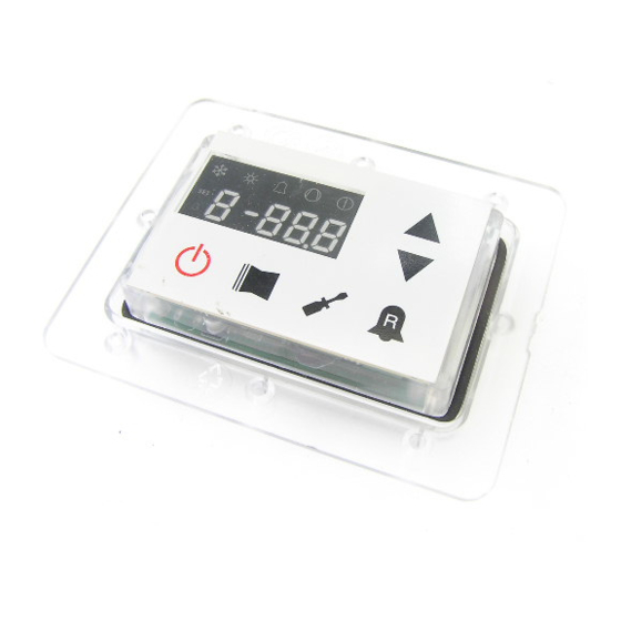
User interface and parameter visualisations The main user interface is represented by a LED panel with capacitive keyboard (touch keys); the visualisations are ar- ranged in three menus: • READINGS menu (key (C) Fig.1) Containing the information (visualisation mode only) relating to current unit functioning. -
Page 13: Readings Menu
Readings menu To access the readings menu, press of the reading itself. To move on to the fying the current reading (it is possible, the key in (Fig.4); once the readings next reading, press the key in (Fig.5); to however, to identify any reading via the menu has been accessed, the monitor go back to the previous one, press the value of the indicator, comparing it with... -
Page 14: User Menu
USER menu To access the USER menu, press the password, press the key in (Fig.7). The rameter, just select it, press the key in key in (Fig.7). Once the key has been monitor will show the index of the USER (Fig.7), modify the assigned value using pressed, you must insert the password parameter and a 3-character string that... -
Page 15: Setting Of Proportional Cooling Band
Setting of proportional cooling band Index - String Parameter function value value This parameter indicates the proportional band applied to the cooling set; this band produces the optimised management of the compressor, only switching it on if the inlet/ 1°C 20°C outlet water temperature (depending on the type of control set by parameter (0) in the installer menu) is greater than the cooling work set (parameter (1) user menu) plus the... -
Page 16: Setting Cooling Temperature Setpoint 1
Setting cooling temperature setpoint 1 Index - String Parameter function value value This parameter indicates the maximum value of the cooling setting, corresponding with -20°C 26°C the minimum outside air temperature (index (7) user menu). This parameter is only visi- ble if the compensation function has been activated (index (5) user menu). -
Page 17: Setting Heating Set 2
Setting heating set 2 Index - String Parameter function value value This parameter indicates the minimum value of the heating setting, corresponding with the maximum outside air temperature (index (C) user menu). This parameter is only visi- 25°C ble if the compensation function has been activated (index (5) user menu). (*) the maxi- mum limit can be configured by means of the parameter (t) of the installer menu Setting the outside air temperature 2 (heating) Index - String... -
Page 18: Installer Menu
INSTALLER menu To access the INSTALLER menu, press key in (Fig.9). The monitor will show the lect it, press the key in (Fig.9), modify the key in (Fig.9). Once the key has been index of the INSTALLER parameter and the assigned value using the arrow keys pressed, you must insert the password a 3-character string that identifi... -
Page 19: Setting Heating Force-Off
Setting heating FORCE-OFF Index - String Parameter function value value The heat pumps check the working temperature (input or output), to which a safety thre- 30°C 70°C shold is connected, and beyond which the compressor is switched off immediately and automatically;... -
Page 20: Setting The Supplementary Electric Heater Or Activating The Boiler
Setting the supplementary electric heater or activating the boiler Index - String Parameter function value value This parameter indicates which logic must be used to manage the supplementary electric heater; the choice of logic is determined by the value set in this parameter so, depending on the value, the settings are: 0 = no supplementary electric heater present on the unit 1 = supplementary electric heater present, but cannot be activated during hot domestic... -
Page 21: Power Dedicated To Domestic Water Production
2 • the pump alarm (as in the previous software version), if the parameter is set at 3 Remember also that by setting this parameter at 3, the moducontrol card is compatible with the previous software version (3.6). -
Page 22: High Room Temperature Standby
Parameter function value value This parameter indicates the speed of communication between supervisor and Moducontrol; this speed is set on the basis of the value selected for this parameter: 0 = 9600 bps 1 = 19200 bps 2 = 38400 bps... -
Page 23: Supervisor Write Enabled
Supervisor write enabled Index - String Parameter function value value This parameter enables the write commands for the supervisor; this enablement is set on the basis of the value selected for this parameter: 0 = write command disabled 1 = write command enabled Remember that the read commands are always active. -
Page 24: Installer 2 Menu
INSTALLER 2 menu To access the INSTALLER_2 menu, follow the same procedure described for the INSTALLER menu; the only difference is the value of the password, which is 31. WARNING The following parameters must only be modifi ed by qualifi ed personnel authorised to install the unit. -
Page 25: Managing The Electric Heater
Managing the electric heater The units with moducontrol offer the Selection logic for electric heater management mode Fig.11 possibility to manage an electric he- ater; this heater can be managed in different ways: • supplementary (the simultaneous Electric heater Electric heater... -
Page 26: Electric Heater Menu
ELECTRIC HEATER menu To access the ELECTRIC HEATER menu, press the key in (Fig.14). The monitor will parameter, just select it, press the key press the key in (Fig.14). Once the key show the index of the ELECTRIC HEA- in (Fig.14), modify the assigned value has been pressed, you must insert the TER parameter and a 3-character string using the arrow keys in (Fig.15), and... -
Page 27: Setting Supplementary Electric Heater Setpoint
Setting supplementary electric heater setpoint Index - String Parameter function value value This parameter indicates the deviation from the heating setpoint, for switching off the 0°C 65°C electric heater (if active) in supplementary mode; as shown in Fig. 1 2 on the previous page (Parameter Sri). -
Page 28: Table Of Dip-Switch Configuration
Remember that some of the options that can be managed from the panel are bound to a specifi c setting of some dip- switches. Dip-switch (A) Default setting of MODUCONTROL DIP-SWITCH DIP-SWITCH (A) DIP-SWITCH (B) Heat reco- very unit ANL H... - Page 29 Dip-switch No. dip Status Function Machine set as heat pump Machine set for cooling only Defrosting only by cycle reversal Defrosting by hot gas injection Glycol water: anti-freeze setting can be modified Anti-freeze setting (parameter B) blocked Output control deactivated Output control activated Safety capacity controls deactivated Safety capacity controls activated...
-
Page 30: Serial Communication Protocol
To enable communication from a supervi- It is also necessary to ensure compliance face with a centralised system via a spe- sion system to the Moducontrol card, you with the following characteristics: cial serial expansion card based on the must set the following parameters: •... - Page 31 ADDRESS DESCRIPTION High pressure switch pre-alarm Flow switch/differential pressure switch (water) pre-alarm Low pressure switch pre-alarm Pre-alarm for absence of NTC1 input probe (SIW) Pre-alarm for absence of NTC2 input probe (SUW) Anti-freeze pre-alarm Pre-alarm for absence of NTC4 input probe (SGP) Pre-alarm for high discharge gas temperature Pre-alarm for absence of compressor delivery transducer High pressure pre-alarm...
- Page 32 ADDRESS DESCRIPTION NOT USED Fault condition pre-alarm (APY) NOT USED NOT USED Reverse cycle valve pre-alarm Pre-alarm for high water inlet temperature Pre-alarm for reverse cycle due to high discharge gas temperature NOT USED NOT USED NOT USED NOT USED NOT USED NOT USED NOT USED...
- Page 33 ADDRESS DESCRIPTION Alarm for IPM protection error (longertek) Alarm for EEPROM error (longertek) Alarm for compressor stalling (longertek) Alarm for absence of communication (longertek) PFC module alarm (longertek) Alarm for cooling over-temperature (APY) Alarm for overcurrent in acceleration (APY) Alarm for overcurrent at steady speed (APY) Alarm for overcurrent in deceleration (APY) Alarm for undervoltage on BUS DC (APY) Overvoltage alarm (APY)
-
Page 34: Read List Register
READ LIST REGISTER: COMANDI LETTURA DISPONIBILI Read Holding Register ADDRESS DESCRIPTION Type of machine: 0 – ANL, 1 – ANLI, 2 – ANR/ANF/SRP, 3 – ANL-C Type of inverter machine 0=longertek 1=APY NTC1 input (TUA) (SIW) NTC2 input (TIA) (SUW) NTC3 input (TSB) (SS) NTC4 input (TGP) (SGP) NTC5 input (TAE) (SAE) -
Page 35: Write List Register
WRITE LIST REGISTER: COMANDI SCRITTURA DISPONIBILI Preset Single Register Preset Multiple Registers ADDRESS DESCRIPTION MIN-MAX LIMITS Cooling setpoint -200 - 260 [°C] Cooling setpoint band 10 - 200 [°C] Heating setpoint 250 - 650 [°C] Heating setpoint band 10 - 200 [°C] Setpoint correction 0 - 3 Cooling setpoint 1... -
Page 36: Recapitulatory Table Of Alarms
Recapitulatory table of alarms the unit, you are advised to contact the After index and cause shown in the table below). A The units have two types of malfunctioning Sales Assistance. To reset the unit you must pre-alarm remains such for 60 seconds; if the warning: switch it off then on again, using the standby •... - Page 37 High force gas temperature This warning appears when the force gas temperature (SGP probe) exce- eds the threshold set in the parameter. The pre-alarm condition is remo- ved with the factory-set temperature (default 125°C). No compressor delivery pressure This warning appears when the compressor delivery transducer is transducer not detected and the machine is set in heat pump mode, or the pre- sence of the DCP is set.
- Page 38 Excessive temperature of cooling blade Overcurrent in acceleration Hardware error. Overcurrent at constant speed Hardware error. Overcurrent in deceleration Hardware error. Undervoltage on BUS DC Overvoltage on BUS DC PFC Converter Fault Error in the Software error. PFC module Overcurrent in acceleration Software error.
- Page 39 AERMEC S.p.A. I-37040 Bevilacqua (VR) Italie – Via Roma, 996 Tel. (+39) 0442 633111 Téléfax 0442 93730 – (+39) 0442 93566 www .aermec. com - info @aermec. com MODUCONTROL NUMÉRO DE SÉRIE DÉCLARATION Les signataires de la présente déclarent sous leur entière responsabilité que l'équipement défini comme suit : DE CONFORMITÉ...
- Page 40 AERMEC S.p.A. si riserva la facoltà di apportare in qualsiasi momento tutte le modifiche ritenute necessarie per il miglioramento del prodotto. Les données mentionnées dans ce manuel ne constituent aucun engagement de notre part. Aermec S.p.A. se réserve le droit de modifier à tous moments les données considérées nécessaires à...
Need help?
Do you have a question about the MODUCONTROL and is the answer not in the manual?
Questions and answers