Sargent Assa Abloy IN120 Installation Instructions Manual
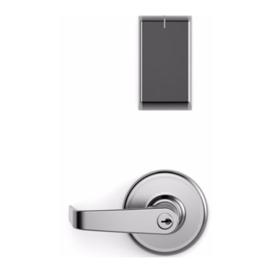
Wifi cylindrical lock
Hide thumbs
Also See for Assa Abloy IN120:
- Installation instructions manual (20 pages) ,
- Installation instructions manual (28 pages)
Advertisement
Advertisement

Subscribe to Our Youtube Channel
Related Manuals for Sargent Assa Abloy IN120


Summary of Contents for Sargent Assa Abloy IN120
-
Page 1: Installation Instructions
IN120 WiFi Cylindrical Lock Installation Instructions A8152C 01/14 Copyright 2014, Sargent Manufacturing Company, an ASSA ABLOY Group company. All rights reserved. Reproduction in whole or in part without the express written permission of Sargent Manufacturing Company is prohibited. -
Page 3: Table Of Contents
équivalente (p.i.r.e.) ne dépasse pas l’intensité nécessaire à l’établissement d’une communication satisfaisante. Any retrofit or other field modification to a fire rated opening can potentially impact the fire rating of the opening, and SARGENT Manufacturing makes no representations or warranties concerning what such impact may be in any specific situation. When retrofitting any portion of an existing fire rated opening, or specifying and installing a new fire-rated opening, please consult with a code specialist or local code official (Authority Having Jurisdiction) to ensure compliance with all applicable codes and ratings. -
Page 4: General Description
This product is operated by six (6) “AA” alkaline batteries, or can be hard-powered using an optional 9-24VDC power supply connected by a harness through the door. SARGENT cylindrical locks are designed with quality components to provide high security, performance and durability. -
Page 5: Parts Breakdown
IN120 Cylindrical Lock Parts Breakdown ITEM PART NUMBER/ORDER STRING DESCRIPTION COLOR/TRIM IN-120-EM01-IP-B HID iCLASS , HID iCLASS SE (SIO-enabled), HID iCLASS Seos™, HID MIFARE Black ® ® ® ® SE, HID DESfire EV1 SE, HID Prox , NFC-enabled mobile phones ®... - Page 6 IN120 Cylindrical Lock Parts Breakdown (Continued) PART NO./ORDER STRING ITEM QTY. DESCRIPTION Outside Lever (Reference Catalog for Available Styles) 10-0043 Lever Retainer Key (In Screw Pack 10-2052) Cylinder Assembly (Reference Catalog for Available Cylinders) Rose (Reference Catalog for Avalable Styles) 10-0792 Spacer Bushing 10-3049...
-
Page 7: Lock Installation
IN120 Cylindrical Lock Lock Installation 1 Prepare Door A. Verify Hand and Bevel of Door Stand on outside of locked door when determining door hand. LHRB RHRB Left Hand Left Hand Right Hand Right Hand Hinges Left Reverse Bevel Hinges Right Reverse Bevel Open Inward Hinges Left... - Page 8 IN120 Cylindrical Lock 2 Install Strike Centerline of Latch Front and Strike Install strike in the door frame (Fig. 2). (2) #8-32 x 3/4" Latch Screws Fig. 2 3 Install Latchbolt 1. Install latch with beveled bolt facing the strike. Inside of Door 2.
- Page 9 IN120 Cylindrical Lock 5 Lock Adjustments A. Lock Preset: • Lockbody holes: 12 and 6 o’clock (Fig. 5). The lock is shipped “preset” and does not require adjustment for 1-3/4” thick doors. Outside of Door Door thickness: 1-3/4” thick Preset Lock Fig.
- Page 10 IN120 Cylindrical Lock 6 Through-Bolt and Door Thickness Adjustment (If Required) A. Remove Outside Lever 1. Insert key, rotate 45° clockwise and hold. 2. Depress lever retainer with push pin tool (provided). 3. Pull lever outward. Outside of Door Fig. 6A B.
- Page 11 IN120 Cylindrical Lock C. Through-Bolt and Door Thickness Adjustment 1. (If necessary) remove outside lever, scalp and spacer bushing (Fig. 6C). Spacer Bushing Scalp Outside Lever Fig. 6C 2. Rotate mounting plate to either align with through-bolt holes in door, or adjust for proper door thickness (Fig. 6D). Refer to markings on through-bolt post (Fig.
- Page 12 IN120 Cylindrical Lock 7 Install Lock 1. From outside of door feed lockbody harness into the lockbody hole (Fig. 7A). For metal door: Feed harness through inside of door (not shown). 2. Continue to feed harness into raceway (towards top of door), exiting raceway hole on inside of door (Fig.
- Page 13 IN120 Cylindrical Lock 8 Secure Lock to the Door 1. Slide inside rose assembly and spacer bushing over lockbody. 2. Position ground lug between (top) #10-32x1-1/4” through-bolt Inside of Door and rose assembly (Fig. 8A). NOTE: Proper placement of ground wire (Fig. 8B) will prevent pinching/damage to the ground wire.
- Page 14 IN120 Cylindrical Lock 10 Outside Reader Installation 1. Orient the reader so the LED lens is at the top. 2. Feed the cable/connector through the door (from outside to inside). 3. Install the reader to the outside of door by aligning the mounting posts with the door preparation holes. Hold the reader flush against door while ensuring proper alignment.
- Page 15 IN120 Cylindrical Lock 10 Outside Reader Installation (Continued) 4. Next feed the cables/connectors through the inside mounting assembly (and gasket if required*). NOTE: Cable lengths exaggerated for illustrative purposes. Inside of Door Gasket* Mounting Plate Reader Harness Lockbody Har- ness Ground Lug Fig.
- Page 16 IN120 Cylindrical Lock 10 Outside Reader Installation (Continued) 9-24VDC Reader Installation of Connectors Power* (4-pin) (24-pin) CAUTION - Do not touch or allow debris to enter connector contacts. Secure the following connectors to their respective terminals (Fig. 10C,D): A. Secure the 24-pin card reader connector. B.
- Page 17 IN120 Cylindrical Lock 11 Installing the Controller 1. Insert bottom tab of controller into slot on mounting plate (Fig. 11A, B). 2. Looking down from top of controller, ensure proper alignment of board-to-board connectors (Fig. 11B) while pivoting controller toward door until two tabs on top snap securely into place on mounting plate (Fig.
- Page 18 IN120 Cylindrical Lock 12 Battery Installation Before installing batteries for the first time: Remove pull tab from its position beneath the coin cell by pulling AA Batteries (6) on tab in direction of arrows printed on tab (Fig. 12). 1. Place (6) “AA” alkaline batteries in the compartment, being careful to align polarity properly.
-
Page 19: Operational Check
IN120 Cylindrical Lock Operational Check 1. Insert key into cylinder and rotate (Fig. 14A). There should be no friction against lock case, wire harness or any other obstructions. 2. Check that the key retracts the latch. 3. The key should rotate freely. 4. - Page 20 New Haven, CT 06511 USA 800-810-WIRE (9473) • www.sargentlock.com Founded in the early 1800s, SARGENT® is a market leader in locksets, cylinders, door closers, exit devices, electro-mechanical products and access control systems for new construction, renovation, and replacement applications. The company’s customer base includes commercial construction, institutional, and industrial markets.
Need help?
Do you have a question about the Assa Abloy IN120 and is the answer not in the manual?
Questions and answers