Table of Contents
Advertisement
Quick Links
Installation Instructions
Installation Instructions
10 Line Cylindrical Lockset
1
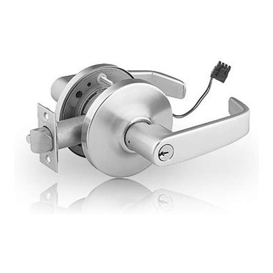
Package Contents
Figure 1
Description
1
Inside Lever
2
Rose Scalp
Screws – mounting
3
plate #6 x 3/4" self-
tapping
4
Spacer bushing
5
Inside rose assembly
Screws – through-
6
bolt #10-32 x 1-1/4"
7
Lockbody
Outside rose
8
assembly
9
Cylinder spacer
10
Cylinder
11
Outside lever
12
Key
13
Push pin
14
Latch
Screws – latch &
15
strike #8-32 x 3/4"
16
Strike
17
Strike box
Door Preparation
2
• All doors should be properly reinforced for lock support. If support is not provided, contact door manufacturer.
• For all metal door preparations, use template A4375 (Not included. See website to download), EXCEPT for functions 10G70 or 10G71
which use template 4409 (not included), or functions 10U93, 10U94, and 10U94-2 which require template A4375.
• For all wood door preparations use template A6719 (included), EXCEPT for functions 10G70 & 10G71.
• Template information is available on our website: www.sargentlock.com.
a. Mark & Drill Holes
IMPORTANT: Fold template onto high
edge of door bevel.
Template
Backset must
Door bevel
match lock (2-
Desired height
3/8" or 2-3/4'
from finished floor
DOOR
FRAME
Figure 2
1-800-727-5477 • www.sargentlock.com
Copyright © 2020 SARGENT Manufacturing Company. All rights reserved. Reproduction in whole or
in part without the express written permission of SARGENT Manufacturing Company is prohibited.
Req
1
2
2
2
1
3
2
1
2
1
1
1
1
Tools Required
1
1
• #2 Phillips screwdriver
1
• Flat-bladed screwdriver
1
• Push pin (provided)
4
1
1
b. Final Door Prep
7/16" (11mm) hole
1" (29mm)
hole
2-1/4"
(57mm)
Figure 3
1-1/8"
(29mm)
7
5
6
4
1 4
Inside of Door
1 5
Figure 1
• 7/16" drill bit
•1" Bore
• 1/8" drill bit
• 2-1/8" Bore
c. Frame Prep for Strike
Figure 4
2-1/8"
(54mm)
hole
5/32" (4mm)
IMPORTANT: Deadlocking latch must
stop on the strike when the door is
closed.
A7133N 12/20
2
9
8
4
1 0
Outside of Door
(Secure Side)
1 6
1 7
Centerline of latch
front and strike
Screws (2)
Tighten after adjustment
#8-32 x 3/4"
Strike
1 2
1 1
1 3
Advertisement
Table of Contents

Subscribe to Our Youtube Channel
Related Manuals for Sargent ASSA ABLOY 10 Series


Summary of Contents for Sargent ASSA ABLOY 10 Series
- Page 1 (29mm) closed. Strike 1-800-727-5477 • www.sargentlock.com Copyright © 2020 SARGENT Manufacturing Company. All rights reserved. Reproduction in whole or A7133N 12/20 in part without the express written permission of SARGENT Manufacturing Company is prohibited.
- Page 2 Install Inside Rose Assembly, Scalp and Lever NOTE: Test for proper operation before closing door. 1-800-727-5477 • www.sargentlock.com A7133 12/20 Copyright © 2020 SARGENT Manufacturing Company. All rights reserved. Reproduction in whole or in part without the express written permission of SARGENT Manufacturing Company is prohibited.
- Page 3 For Degree and XC LFIC cores, retainer must be installed on tailpiece. 1-800-727-5477 • www.sargentlock.com A7133 12/20 Copyright © 2020 SARGENT Manufacturing Company. All rights reserved. Reproduction in whole or in part without the express written permission of SARGENT Manufacturing Company is prohibited.
- Page 4 Screws (2) #6 3/4" Rose Scalp to be removed with flat-bladed screwdriver Screws (2) #8-32x3/4" SARGENT Manufacturing Company WARNING 100 Sargent Drive This product can expose you to lead New Haven, CT 06511 USA which is known to the state of California...
Need help?
Do you have a question about the ASSA ABLOY 10 Series and is the answer not in the manual?
Questions and answers