Table of Contents
Advertisement
Quick Links
Advertisement
Table of Contents

Related Manuals for Renishaw TONiC T20 1 Series


Summary of Contents for Renishaw TONiC T20 1 Series
- Page 1 Installation guide M-9653-9161-04-C TONiC T20x1 RESM angle encoder system ™...
-
Page 2: Table Of Contents
Contents Legal notices Storage and handling TONiC T20x1 readhead installation drawing Ti interface drawing RESM20 installation drawing (‘A’ section) RESM20 installation drawing (‘B’ section) Select a RESM20 ring mounting option Equipment for taper mounting Taper mount method Equipment for interference fit mounting Interference fit method TONiC quick-start guide System connection... -
Page 3: Legal Notices
Renishaw. including interference that may cause undesired operation. The user is cautioned that any changes or modifications not expressly approved by Renishaw plc or authorised Trade marks representative could void the user’s authority to operate the equipment. -
Page 4: Storage And Handling
Storage and handling RESM20 is a non-contact optical encoder that However, in harsh environments such as machine provides good immunity against contaminants such tool applications, protection should be provided to as dust, fingerprints and light oils. prevent ingress of coolant or oil. Ring and readhead Ring only Readhead only... -
Page 5: Tonic T20X1 Readhead Installation Drawing
TONiC T20x1 readhead installation drawing Dimensions and tolerances in mm Optical centreline (incremental and reference mark) ‘A’ section ring – Offset 1.75 ±0.5 ‘B’ section ring – Offset 3.25 ±0.5 8.75 * (Yaw tol. ±0.4°) (Roll tol. ±0.5°) 2 off mounting holes M2.5 through, 0.25 0.08 counterbored Ø3 x 2.75 deep from... -
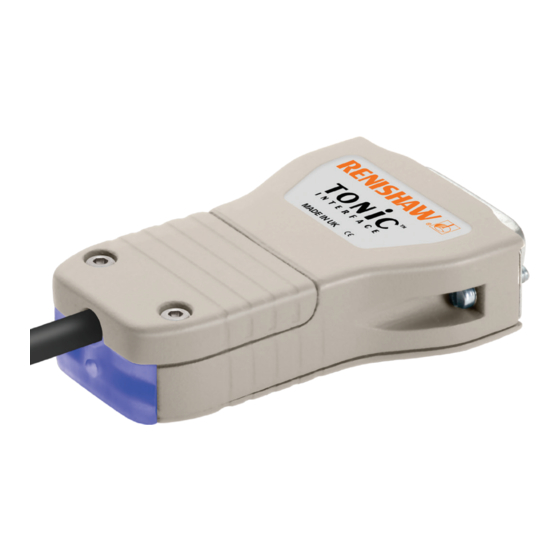
Page 6: Ti Interface Drawing
Ti interface drawing Dimensions and tolerances in mm 6 minimum R > 20 Dynamic bend radius* R > 10 Static bend radius CAL/AGC push button switch access hole Ø2.4 33.3 Diagnostic LED (Ti0004 - Ti20KD and TD4000 - TD0040) Cover plate 4-40 UNC x 2 CAL button operation Push and release (< 3 seconds) - Calibration (CAL) routine enable/disable Push and release (> 3 seconds) - Automatic Gain Control (AGC) enable/disable... -
Page 7: Resm20 Installation Drawing ('A' Section)
RESM20 installation drawing (‘A’ section) Dimensions and tolerances in mm Nominal Line Mounting holes Readhead N holes equally spaced on PCD ØDH Ø3.5 external count (mm) (mm) model through c/bore top face Ø6 × 3 deep diameter θ (mm) (mm) 52.20 30.04 8 192... -
Page 8: Resm20 Installation Drawing ('B' Section)
RESM20 installation drawing (‘B’ section) Dimensions and tolerances in mm Nominal Line Mounting holes Readhead external count (mm) (mm) model diameter θ N holes equally spaced on PCD ØDH Ø3.5 through (mm) (mm) 52.20 32.04 8 192 30° T2021 52.10 32.00 N holes equally spaced on PCD ØDH M3 ×... -
Page 9: Select A Resm20 Ring Mounting Option
Select a RESM20 ring mounting option Taper Mount Interference fit ‘A’ Section ‘B’ Section Not applicable Notes Recommended for all installations Alternative installation Enables simplest adjustment. Will not correct eccentricity of the Offers highest accuracy. supporting shaft. Enables eccentricity to be compensated. Offers excellent mechanical stability against thermal cycling, shock and vibration. -
Page 10: Equipment For Taper Mounting
Required parts: Optional parts: Appropriate RESM20 ‘A’ section ring (‘RESM20 installation drawing (‘A’ section)’, page 5) Renishaw scale wipes (A-9523-4040) Appropriate number of screws for ring size (‘RESM20 installation drawing (‘A’ section)’, page 5) Lint-free cloth NOTE: Recommended screw type M3 × 0.5: ISO 4762/DIN 912 grade 10.9 minimum/ANSI B18.3.1M. -
Page 11: Taper Mount Method
Taper mount method Step 1 Mounting shaft specifications Step 2 Remove the protective film from the surface of the the RESM20 ring. Recommended taper roundness: Clean shaft taper and internal taper of RESM20 as recommended in ‘Storage and handling’, page 2 Diameter (mm) Roundness Insert the first screws:... - Page 12 6 equally spaced M3 screws. more details. • For RESM20 rings with 20 mounting holes, insert Clean ring using Renishaw scale cleaning wipes or a 8 equally spaced M3 screws (in four groups of two) clean, dry, lint-free cloth. between existing screws.
-
Page 13: Equipment For Interference Fit Mounting
Required parts: Optional parts: Appropriate RESM20 ‘A’ or ‘B’ section ring (‘RESM20 installation drawing (‘A’ section)’, page 5) Renishaw scale wipes (A-9523-4040) (‘RESM20 installation drawing (‘B’ section)’, page 6) Lint-free cloth Appropriate number of screws for ring size (‘RESM20 installation drawing (‘A’ section)’, page 5) (‘RESM20 installation drawing (‘B’... -
Page 14: Interference Fit Method
Insert required number of screws into all mounting holes. 95.045 95.023 Tighten all screws. 130.052 Clean ring using Renishaw scale cleaning wipes or a clean, dry, lint-free cloth. 130.027 NOTES: 180.052 Ensure that all screws are tightened to 1.6 Nm. -
Page 15: Tonic Quick-Start Guide
TONiC quick-start guide This section is a quick-start guide to installing a TONiC system. More detailed information on installing the TONiC system is contained on pages 14 to 18 of this installation guide. INSTALLATION Ensure RESM20 ring, readhead optical window and mounting faces are clean and free from obstructions. Plug the readhead cable into the Ti/TD interface under the cover plate and reassemble interface. -
Page 16: System Connection
System connection Approved ESD precautions must be followed at all times during readhead and interface electrical connections. The readhead is connected to the Disconnecting the readhead Ti/TD interface via a small, rugged connector to allow for easy feed-through during installation. Remove the cover plate on the interface (2 x M2.5 hex head screws). -
Page 17: T20X1 Readhead And Resm20 Compatibility
™ mounting hole to the left of the ‘Renishaw’ logo within ±0.5 mm. No external actuators or physical adjustment are required. TONiC RESM20 angle encoder system installation guide... -
Page 18: Readhead Mounting And Alignment
Alarm may result in axis position error, re-datum to continue. See the product nomenclature for interface configuration in the TONiC encoder system Data sheet (Renishaw part no. L-9517-9337). This can be downloaded from our website at www.renishaw.com/tonicdownloads and is also available from your local representative. -
Page 19: System Calibration
System calibration Calibration is an essential operation that completes readhead set-up, with the optimum incremental and Step 2 – Reference mark phasing reference mark signal settings stored in the readhead’s non-volatile memory. Move the readhead back and forth over the selected reference mark until the CAL LED stops Before system calibration: flashing and remains off. -
Page 20: Restoring Factory Defaults
Restoring factory defaults When re-installing the system, or in the case of continued calibration failure, factory defaults should be restored. To restore factory defaults: Switch system off. Press and hold the CAL button whilst switching the system on. The CAL LED on the readhead will flash several times, indicating that the factory defaults have been restored. Release CAL button. -
Page 21: Output Signals
P and Q limit actuators are not suitable for ring encoder (RESM) installation. Sine − Green Limit switch signal detail is included here for information only. Reference mark Violet Analogue Please contact your local Renishaw representative if you require limits on your rotary installation. − Grey Limits Pink Open collector Black Set-up... -
Page 22: Speed
Speed Maximum speed (m/s) Clocked output Ti0004 Ti0020 Ti0040 Ti0100 Ti0200 Ti0400 Ti1000 Ti2000 Ti4000 Ti10KD Ti20KD option (MHz) 5 µm 1 µm 0.5 µm 0.2 µm 0.1 µm 50 nm 20 nm 10 nm 5 nm 2 nm 1 nm 6.48 3.24 1.62... -
Page 23: Electrical Connections
Electrical connections Grounding and shielding Recommended signal termination Extension cable Digital outputs Customer maximum 50 m electronics dependent upon Ti / TD interface Readhead Inner shield clocked output option Customer 220 pF A B Z E+ electronics Output signals Cable Z = 120R 120R Outer shield... -
Page 24: Output Specifications
Output specifications Digital output signals Form – Square wave differential line driver to EIA RS422A (except limits P and Q) Incremental † 2 channels A and B in quadrature (90° phase shifted) Alarm † Asynchronous pulse Line driven Signal period > 15 ms Resolution Alarm asserted when:... - Page 25 Output specifications (continued) Analogue output signals Set-up * Incremental 2 channels V and V differential sinusoids in quadrature centred on 1.65 V (90° phase shifted) 3.3 (nom) 20 µm 0.7 to 1.35 Vpp with Green Voltage at V +) −(V −) LED indication, (readhead) and 120R termination.
-
Page 26: General Specifications
Maximum cable length (m) 40 to 50 < 40 analogue CAUTION: Renishaw encoder systems have been designed to the relevant EMC standards, but must be correctly integrated to achieve EMC compliance. In particular, attention to shielding arrangements is essential. RESM20 ring specifications Material... - Page 27 New Mills, Wotton-under-Edge uk@renishaw.com Gloucestershire, GL12 8JR United Kingdom www.renishaw.com For worldwide contact details, visit www.renishaw.com/contact Renishaw plc. Registered in England and Wales. Company no: 1106260. Part no.: M-9653-9161-04-C Registered office: New Mills, Wotton-under-Edge, Gloucestershire, GL12 8JR, UK. Issued: 11.2022...
Need help?
Do you have a question about the TONiC T20 1 Series and is the answer not in the manual?
Questions and answers