Advertisement
- 1 Dimensions
- 2 Connection Diagrams
- 3 Proper Use
- 4 Safety Precautions
- 5 Technical Data
- 6 Complementary Products
- 7 Mounting instructions
- 8 Adjustment
- 9 Function of Teach-In (pin 2)
- 10 Additional Functions for activation via the interface
- 11 Causes for Triggering of Contamination Indication (red LED)
- 12 Proper Disposal
- 13 Documents / Resources
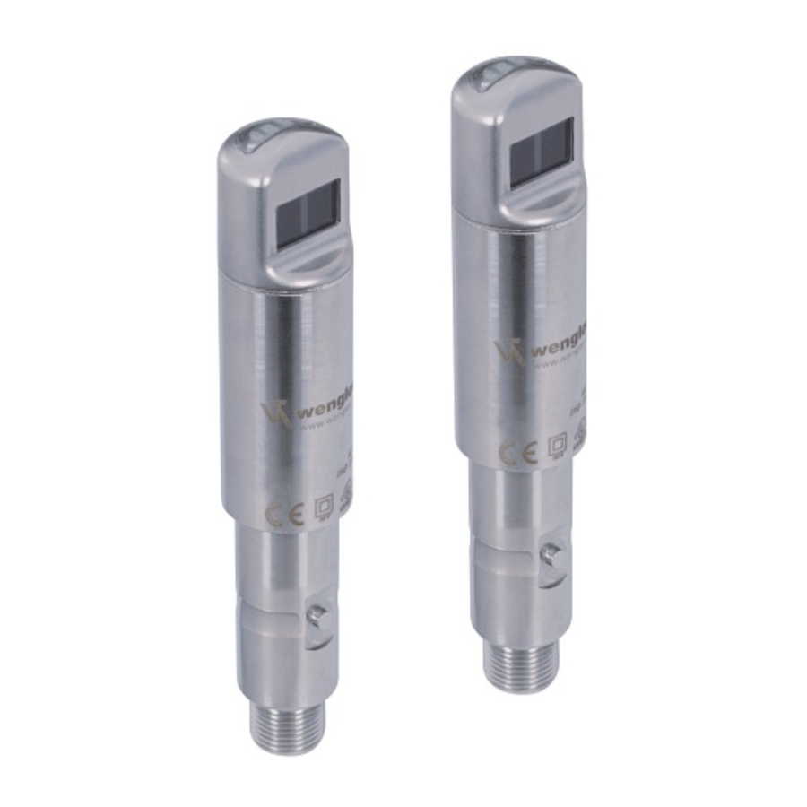
Dimensions
OSII


- Transmitter diode
- no function
OEII


- no function
- Receiver diode
Connection Diagrams

+ Supply Voltage "+"
− Supply Voltage "0 V"
A Switching output / NO
nc not connected
 Switching output / NC
T Teach Input
U Test Input
Control Panel Receiver

Control Panel Emitter

01 = Switching Status Indicator
02 = Contanimation Warning
06 = Teach Button
04 = Display of functions
Proper Use
This wenglor product has to be used according to the following functional principle:
Through Beam Sensors
The transmitter and receiver in through-beam sensors are integrated in separate housings. The output switches if the light beam is interrupted. The function of the transmitter and receiver can be tested with a test input.
Through-beam sensors are available with laser light, red light or infrared light. The fine laser beam creates a small spot of light, which can be used to reliably detect even the smallest parts. Their good visibility facilitates easy adjustment and commissioning, even at great distances. In the case of some laser through-beam sensors, the focus is adjustable. Aligning through-beam sensors with red light is very easy thanks to the visible light spot.
Safety Precautions
- This operating instruction is part of the product and must be kept during its entire service life.
- Read this operating instruction carefully before using the product.
- Installation, start-up and maintenance of this product has only to be carried out by trained personnel.
- Tampering with or modifying the product is not permissible.
- Protect the product against contamination during start-up.
- These products are not suited for safety applications.
- Not a safety component in accordance with the EU Machinery Directive.
Technical Data
| Range | 4000 mm |
| Opening Angle | 3° |
| Switching Hysteresis | < 15 % |
| Light Source | Red Light |
| Service Life (T = 25°C) | 100 000 h |
| max. Ambient Light | 10 000 Lux |
| Supply Voltage | 10...30 V |
| Current Consumption (Ub = 24 V) | < 40 mA |
| Switching Frequency | 500 Hz |
| Temperature Drift | < 10 % |
| Temperature Range | − 25...60°C |
| Switching Output Voltage Drop | < 2,5 V |
| Short Circuit Protection | yes |
| Reverse Polarity Protection | yes |
| Overload Protection | yes |
| RS-232 with Adapter Box | yes |
| Teach Mode | NT, MT, XT |
| Setting Method | Teach-In |
| Housing Stainless | Stainless Steel 316L |
| Degree of Protection | IP68 / IP69K |
| Connection | M12 × 1 |
| Protection Class | III |
| Output | PNP NO / NC switchable |
| Order-No. | OEII403C0103 OSII403Z0103 | OEII403C0203 OSII403Z0203 |
| Optic cover | PMMA | Glass |
Complementary Products
(see catalog)
wenglor offers Connection Technology for field wiring.
| Suitable Mounting Technology No. |  |
| Suitable Connection Technology No. |  |
| Adapter Box A232 | |
| InoxLock Set | |
Mounting instructions
During operation of the sensors, the corresponding electrical and mechanical regulations, as well as safety regulations must be observed. The sensor must be protected from mechanical impact.
Adjustment

Function of Teach-In (pin 2)
External Teach-In
The switching point can be taught in by applying a voltage of 24 V for approximately 1 second.
Switching Between the Teach Modes
Apply 24 V to the Teach-In input for at least 10 seconds, until the LED changes over from fast to slow blinking.
| Blinking | TEACH Mode | NC / NO |
| 1× | Normal Teach-In | NO |
| 2× | NC | |
| 3× | Minimal Teach-In | NO |
| 4× | NC | |
| 5× | Maximal Teach-In | NO |
| 6×* | NC |
*preset configuration
- Each tome a brief pulse is applied to the Teach-In input, switching to the next Teach-In mode occurs.
- If the Teach-In input is not activated for a period of 15 seconds, the sensor is automatically switched back to the normal display mode.
- Repeat the Teach-In process in accordance with the setup instructions.
Reset
Via the following reset sequence on PIN 2 you can reset the Sensor settings to the delivery status:

The RESET is approved by 3× blinking of the yellow LED. In case of a false reset sequence on PIN 2 the red LED blinks and the Sensor isn't reset to the delivery status.
Disabling the Teach Key
If 24 V is continuously connected to the external Teach-In input, the sensor is locked and protected against inadvertent readjustment.
Additional Functions for activation via the interface
On- / Off-Delay
Either pull-in or release delay can be activated at the sensor via the interface. Delay time can be adjusted. The A232 adapter box is required in order to be able to connect the sensor.
The Switching Frequency can be changed via the interface from 1000 Hz (delivery status) to 1600 Hz.
Interface Protocol available at:www.wenglor.com
Function Diagrams LED's on Control Panel
| Switching Status | yellow LED Display of functions | red LED Contamination Indication | Remarks |
| No object |  | | Operation o.k. |
| No object | |  | adjust pot until red LED off, adjust sensor or clean lens |
| Object present | | | Operation o.k. |
Causes for Triggering of Contamination Indication (red LED)
- Contaminated sensor
- Distance between the sensor and the object / reflector is too great
- Incorrect installation
- Aged emitter diodes
Test Input
If the test input is open or connected with minus, the barrier works normally.
If it is connected with plus, the sensor switches off. The barrier is tested via this changing of the switching status.
Proper Disposal
wenglor sensoric GmbH does not accept the return of unusable or irreparable products. Respectively valid national waste disposal regulations apply to product disposal.
EC Declaration of Conformity
The EC declaration of conformity can be found on our website at www.wenglor.com in download area.

wenglor sensoric GmbH
wenglor Straße 3
88069 Tettnang
( +49 (0)7542 5399-0 info@wenglor.com
For further wenglor contacts go to: www.wenglor.com
Right of modifications reserved
01.02.2016

Documents / Resources
References
Download manual
Here you can download full pdf version of manual, it may contain additional safety instructions, warranty information, FCC rules, etc.
Download Wenglor OEII403C0103/203, OSII403Z0103/203 Operating Instructions
Advertisement


Need help?
Do you have a question about the OEII403C0103 and is the answer not in the manual?
Questions and answers