
Subscribe to Our Youtube Channel
Related Manuals for Wenglor OPT2001


Summary of Contents for Wenglor OPT2001
- Page 1 OPT2001 OPT2002 OPT2003 OPT2004 OPT2005 OPT2006 High-performance distance sensor Operating Instructions Available as PDF only Status: 28.01.2016 www.wenglor.com...
-
Page 2: Table Of Contents
Index Proper Use Safety Precautions Declaration of Conformity Technical Data Installation Instructions Initial Operation Function Adjustment 8.1. Manual Adjustments 8.2. Special Settings Maintenance Instructions 10. Proper Disposal... -
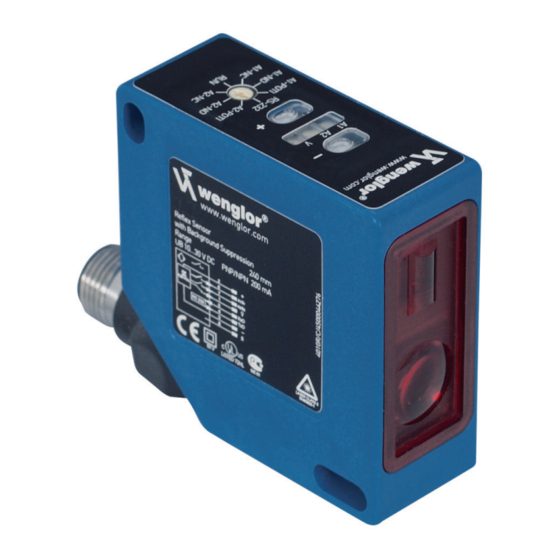
Page 3: Proper Use
1. Proper Use This wenglor product has to be used according to the following functional principle: High-performance distance sensor High performance distance sensors which use the principle of angle measurement determine the distance between the sensor and the object. These sensors have small working ranges (under 1 m) and recognize objects with high precision. -
Page 4: Declaration Of Conformity
3. Declaration of Conformity The EC declaration of conformity can be found on our website at www.wenglor.com in download area. RoHS... -
Page 5: Technical Data
4. Technical Data OPT2001 OPT2003 OPT2005 Optical Data Working Range 30…80 mm 40...160 mm 50...350 mm Measuring Range 50 mm 120 mm 300 mm Resolution < 8 µm < 20 µm < 50 µm Resolution (Speed-Mode) < 12 µm < 30 µm <... - Page 6 OPT2002 OPT2004 OPT2006 Optical Data Working Range 30…80 mm 40…160 mm 50…350 mm Measuring Range 50 mm 120 mm 300 mm Resolution < 8 µm < 20 µm < 50 µm Resolution (Speed-Mode) < 12 µm < 30 µm < 80 µm Linearity 0,1 % 0,1 %...
-
Page 7: Connection Diagram
Connection Diagram Supply Voltage + Contamination/Error output (NO) Emitted light disengageable Analogue output O – Ground for the analogue output – Supply Voltage 0 V Shielding Housing Dimensions = Transmitter Diode = Receiver Diode... -
Page 8: Installation Instructions
Control Panel On the control panel you find the Plus key and the Minus key, several LEDs and the rotary selector switch. The rotary selector switch is used for choosing the setting- and operation functions. = Minus key (with LED) ... -
Page 9: Adjustment
Outputs Analog Output The analog output is connected to analog earth. The analog output can be configured as a current output or a voltage output. If you have the choice we recommend the use of the voltage output (reduced current consump- tion). - Page 10 Set Input The Input can be used as follows: Emitted Light can be switched off at 24 V (La) or Emitted Light can be switched off at 0 V (La) . • Rotary Selector Switch Ý to RxD/La Mode è The U-LED and I-LED indicate the current configuration. RxD is preset in the delivery status. By pressing the Plus or the Minus key, the configuration can be changed.
- Page 11 Operate the sensor with high speed (Speed-Mode) • Set the rotary selector switch Ý to RES. / SPEED-MODE è The red F-LED lights up è The yellow U-LED lights up: Sensor presently set to high speed è The yellow I-LED lights up: Sensor presently set to high Resolution •...
-
Page 12: Special Settings
8.2. Special Settings Adjusting the filter function: • Set the rotary selector switch Ý to FILTER ADJUST è The red F-LED lights up è The yellow LEDs are off: Filter function is presently disabled è Yellow LEDs blink once followed by a pause: filter currently set to level 1 (1/4 cut-off frequency) è... -
Page 13: Maintenance Instructions
• It is advisable to clean the lens and the display, and to check the plug connections at regular intervals. • Do not clean with solvents or cleansers which could damage the device. 10. Proper Disposal wenglor sensoric GmbH does not accept the return of unusable or irreparable products. Respectively valid national waste disposal regulations apply to product disposal.
Need help?
Do you have a question about the OPT2001 and is the answer not in the manual?
Questions and answers