Table of Contents

Related Manuals for Wenglor OPT2172-74


Summary of Contents for Wenglor OPT2172-74
- Page 1 OPT2172 – 74 High-Performance Distance Sensors Operating Instructions Translation of the Original Operating Instruction Subject to change without notice Available as PDF version only Version: 1.0.0 Status: 16.11.2020 www.wenglor.com...
-
Page 2: Table Of Contents
Table of Contents 1. General ...........................3 1.1 Information Concerning these Instructions ..................... 3 1.2 Explanations of Symbols ......................... 3 1.3 Limitation of Liability ..........................4 1.4 Copyrights ..............................4 2. For Your Safety ........................5 2.1 Use for Intended Purpose ........................5 2.2 Use for Other than the Intended Purpose .................... -
Page 3: General
1. General 1.1 Information Concerning these Instructions • These instructions apply to the product with ID code OPT2172 – 74. • They make it possible to use the product safely and efficiently. • These instructions are an integral part of the product and must be kept on hand for the entire duration of its service life. -
Page 4: Limitation Of Liability
• wenglor assumes no liability for printing errors or other inaccuracies contained in these operating instruc- tions, unless wenglor was verifiably aware of such errors at the point in time at which the operating instruc- tions were prepared. -
Page 5: For Your Safety
• The product is not suitable for use in potentially explosive atmospheres. • The product may only be used with accessories supplied or approved by wenglor, or combined with approved products. A list of approved accessories and combination products can be accessed at www.automationdirect.com on the product detail page. -
Page 6: Personnel Qualifications
2.3 Personnel Qualifications • Suitable technical training is a prerequisite. • In-house electronics training is required. • Trained personnel must have uninterrupted access to the operating instructions. DANGER! Risk of personal injury or property damage in case of incorrect initial start-up and maintenance! Personal injury and damage to equipment may occur. -
Page 7: Technical Data
3. Technical Data Optical Data Working range 0…1000 mm Setting range 100…1000 mm Switching hysteresis < 20 mm Light source Laser (red) Wavelength 680 nm Service life (ambient temp. = +25° C) 100000 h Laser class (EN 60825-1) Beam Divergence <... -
Page 8: Spot Diameter
Order No. Technical Data OPT2172 OPT2173 OPT2174 Mounting technology no. Cable 200 mm with plug Cable 200 mm with plug Connection M8×1, 4-pin M12×1, 4-pin M8×1, 4-pin Interface IO-Link V1.1 Number of switching outputs 2 programmable Setting Method Teach-in MTTFd (EN ISO 13849-1) 1021,76 a Supply power with IO-Link 18…30 V... -
Page 9: Layout
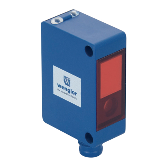
3.3 Layout OPT2172 OPT2173 High-Performance Distance Sensors... -
Page 10: Control Panel
1 = receiver diode 2 = emitter diode M3 screw = 0,5 Nm Dimensions specified in mm (1 mm = 0.03937”) 3.4 Control Panel OPT2172-74 A 23 5a 68 6a 06 = teach-in key 5a = switching status display, A1... -
Page 11: Scope Of Delivery
3.5 Scope of Delivery • Sensor • Commissioning Instructions • Mounting-Set 01 4. Transport and Storage 4.1 Transport Upon receipt of shipment, the goods must be inspected for damage in transit. In the case of damage, con- ditionally accept the package and notify the manufacturer of the damage. Then return the device, making reference to damage in transit. -
Page 12: Installation And Electrical Connection
5. Installation and Electrical Connection 5.1 Installation • Protect the product from contamination during installation. • Observe all applicable electrical and mechanical regulations, standards, and safety rules. • Protect the product against mechanical influences. • Make sure that the sensor is mounted in a mechanically secure fashion. •... - Page 13 Legend Encoder A/A (TTL) Platinum measuring resistor Encoder B/B (TTL) Supply Voltage + not connected Encoder A Supply Voltage 0 V Test Input Encoder B Supply Voltage (AC Voltage) Test Input inverted Digital output MIN Switching Output (NO) Trigger Input Switching Output (NC) Digital output MAX...
-
Page 14: Diagnostics
5.3 Diagnostics P1KY001 – 004 Causes for Triggering the Error Messages (blinking LED at approx. 2,5 Hz): Display LED Diagnosis/Cause Elimination Contamination Carefully clean the optic cover with a cloth. Continuous blinking • Increase the sensor’s switching distance. at approx. 2.5 Hz Unreliable working range •... - Page 15 Contamination Warning Flowcharts Transmit Time Sensor no contamination Object Object Object Object not detected detected not detected Switching Status Indicator beginning contamination Object Object Object Object not detected detected not detected Switching Status blinking Indicator advanced contamination Object Object Object not detected not detected not detected...
-
Page 16: Settings
6. Settings Object Detection Directly in Front of the Background or Underlying Surface • Adjust and securely mount the sensor in accordance with the installation instructions making sure that the object lies within the beam emitted by the sensor. • Remove the object and slowly turn the potentiometer back down until the sensor is deactivated. The back- ground or the underlying surface is now suppressed. - Page 17 OPT2172 – 74 (Sensors with Teach-in) The switching distance to the object can be taught in for both outputs by pressing the teach-in key on the sensor (foreground teach-in). Sensor Teach-in distance Object Switching point Foreground Teach-In for Switching Output 1 1.
-
Page 18: Settings Via Io-Link
7. Settings via IO-Link OPT2172 – 74 (Sensors with Teach-in) Further settings can be entered to the sensor via the IO-Link interface. In addition to foreground teach-in (default setting), there’s also a background teach-in option for both outputs. Additionally, there’s also a window teach-in option for both outputs. Process and parameters data, as well as the interface protocol and the IODD, can be found at www.automationdirect.com in the product’s separate download area. -
Page 19: Locking
7.3 Locking If 18 to 30 V DC is continuously applied to the teach-in input, the teach-in key is locked and protected against inadvertent changes. 1. Change the A1/A2 pin function to external teach-in. 2. Permanently connect pin A2 to voltage within a range of 18 to 30 V DC. 3. -
Page 20: Test Mode
• Do not clean the sensor with solvents or cleansers which could damage the product. • The product must be protected against contamination during initial start-up. 9. Proper Disposal wenglor sensoric GmbH does not accept the return of unusable or irreparable products. Respectively valid national waste disposal regulations apply to product disposal. Maintenance Instructions... -
Page 21: Appendix
10. Appendix 10.1 List of Abbreviations Abbreviation Meaning IODD IO Device Description MTTFd Mean Time to Dangerous Failure 10.2 Change Index, Operating Instructions Version Date Description/Change 1.0.0 16.11.2020 Initial version of the operating instructions 10.3 EU Declaration of Conformity The EU declaration of conformity can be found on our website at www.automationdirect.com in the product’s download area.
Need help?
Do you have a question about the OPT2172-74 and is the answer not in the manual?
Questions and answers