
Related Manuals for Wenglor OPT2011


Summary of Contents for Wenglor OPT2011
- Page 1 OPT2011 High-performance distance sensor Operating Instructions Available as PDF only Status: 16.08.2018 www.wenglor.com...
-
Page 2: Table Of Contents
Table of Contents Use for Intended Purpose Safety Precautions 2.1. Safety Precautions 2.2. Laser/LED warning EC Declaration of Conformity Device Features 4.1. Connecting the Sensor 4.2. Housing Dimensions 4.3. Control Panel Mounting instructions Initial Operation 6.1. Initial Operation 6.2. Default Settings Functional Overview 7.1. - Page 3 7.4. Analog 7.5. Display 7.5.1. Display Mode 7.5.2. Display Intensity 7.6. Expert Menu 7.7. Filter 7.8. Laser 7.9. E/A Test 7.9.1. E/A Test – Test A1 or A2 7.9.2. E/A Test – Test Ana U or I 7.10. Language 7.11. Info 7.12.
-
Page 4: Use For Intended Purpose
2.2. Laser/LED warning Class Laser 1 (EN 60825-1) LASER CLASS 1 Observe all applicable standards EN60825-1 and safety precautions. 2007 3. EC Declaration of Conformity The EC declaration of conformity can be found on our website at www.wenglor.com in download area. RoHS... -
Page 5: Device Features
4. Device Features Order Number OPT2011 Working Range 50...3050 mm Measuring Range 3000 mm Reproducibility 1 mm Linearity Deviation (200…3050 mm) 7 mm Linearity Deviation (50…200 mm) 15 mm Switching hysteresis 3…20 mm Light Source Laser light (red) Laser Class Supply Voltage 18…30 V DC... -
Page 6: Connecting The Sensor
Dependence of Hysteresis and reproducibility on the Sampling Rate on white (90 % Remission) OPT2011 Default setting for min. Set Filter Reproducibility in mm hysteresis in mm Default Settings Power-on Drift The following table provides information on the power-on drift during the warm-up phase. -
Page 7: Housing Dimensions
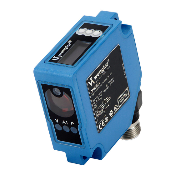
4.2. Housing Dimensions 1 = Transmitter Diode 2 = Receiver Diode 4.3. Control Panel 20 = Enter Button 22 = Up Button 01 = Switching Status Indicator 23 = Down Button 02 = Contamination Warning 60 = Display 68 = Supply Voltage Indicator 5. -
Page 8: Initial Operation
6. Initial Operation 6.1. Initial Operation Before the configuration, connect the Sensor to 18…30 V DC. The desired menu language must be selected after initial start-up, and after each reset (see fig. 1). Fig. 1: Set menu language The functions of the keys appear in the display as follows: : Navigate up. -
Page 9: Default Settings
If a setting is adjusted, it becomes active when the configuration menu is exited. Important: Do not use any sharp objects to press the keys when configuring settings, because they might otherwise be damaged. 6.2. Default Settings OPT2011 E/A 1 Switching output Pin Function E/A 2... -
Page 10: Functional Overview
7. Functional Overview Switch Error Contaminate Analog** E/A1 Pin Function Laser E/A2 Ext T Ax Depends on pin function E/A1: T Foreground Press <T> A1 Switch T Background for Teach-In A1 Error T Window A1 Contaminate Poti Value in mm E1 Laser Hysteresis Value in mm... - Page 11 Filter Laser Depends on pin function E/A1 and E/A2: Test A1 Test A2 E/A Test Value in V resp. I Test Analog Test E1 Run Mode Input Test E2 Deutsch English Language Francais Espanol Italiano Display order number and Info Sensor version Reset Press <R>...
-
Page 12: Run
The following explains the functions behind the individual menu items. 7.1. Run The Sensor switches into display mode. Selected pin function E/A1 (E/A2) Bar graph display with respective status of the current mea- sured value relative to the measuring 1500 mm range Current measured value in mm The set function of the pins is symbolically shown as follows:... -
Page 13: Function Of E/A1 And E/A2
7.3. Function of E/A1 and E/A2 Depending on the pin function that has been set, the selected name is displayed for the menu item, e.g., A1 Switch or E1 Laser. The menu items each contain the following sub-items: For switching output If the pin is set as a switching output, the following functions can be set: A1 Switch/A2 Switch Sensor settings for switching outputs... -
Page 14: Switching Output Foreground Teach-In
7.3.1. Switching Output Foreground Teach-In Teach-In is performed while the sensor spot is aligned to the object. The switching distance is then automati- cally set to a distance which is slightly greater than the clearance between the sensor and the object. The sen- sor is thus activated for all objects whose distance to the sensor is equal to or less than the distance to the object used for the Teach-In procedure. -
Page 15: Switching Output Window Teach-In
T Backgrnd Background Teach-In Press <T> for Teach-In Background process Teach-In 1) Align light spot to background (e.g., on conveyor belt). 2) Press “T” key. –> The switching point is learned. Note: • The switching point can be recalibrated in the menu item Poti (see chapter 7.3.4) if needed. -
Page 16: Switching Output Poti
7.3.4. Switching Output Poti Potentiometer Vary switching point Switching point in mm The switching point can be manually varied by pressing the “+” or “–” keys. You can keep a key pressed for a longer time in order to make larger numerical jumps. 7.3.5. -
Page 17: Switching Output No/Nc
7.3.8. Switching Output NO/NC Configuration of the outputs NO/NC The output is set as a normally open contact by pressing the “NO” key. The output closes immediately when an object reaches the switching point. The output is set as a normally closed contact by pressing the “NC” key. The out- put opens immediately when an object reaches the switching point. -
Page 18: Switching Output Pulse Length
7.3.11. Switching Output Pulse Length The pulse length defines how long the switching state is held. The function can be combined with a response time delay. Object Pulse Length Impulse ON Delay Pulse combined with ON Delay Pulse Length Note: The menu item is only visible if Expert Menu “On” has been set. Pulse Set pulse length Pulse length in ms... -
Page 19: Analog
7.4. Analog The menu item “A2 Analog” is present for the Sensor OPT2011 if pin 2 is set as an analog output. Analog Settings of the analog output Mode U/I Mode U/I: Set analog output to a voltage or current output.. The analog output Teach-In can be set as a voltage output by pressing the “U”... -
Page 20: Display Intensity
7.5.2. Display Intensity Intensity Set the display intensity Min Min: The intensity of the display is set to a minimum value. Normal Normal: The intensity of the display is set to a medium value. Max Max: The intensity of the display is set to a maximum value. ... -
Page 21: Laser
7.8. Laser Transmitted light can be either deactivated or activated with the help of the Laser menu. Note: The menu item is only visible if Expert Menu “On” has been set. Laser Switch transmitted light on or off ON Switch transmitted light on ... -
Page 22: Language
7.10. Language The menu language can be changed in the menu item “Language”. The user is automatically prompted for his desired language at initial operation and after each reset. Note: The menu item is only visible if Expert Menu “On” has been set. Language Set menu language ... -
Page 23: Password
• It is advisable to clean the lens and the display, and to check the plug connections at regular intervals. • Do not clean with solvents or cleansers which could damage the device. 9. Proper Disposal wenglor sensoric gmbh does not accept the return of unusable or irreparable products. Respectively valid national waste disposal regulations apply to product disposal.
Need help?
Do you have a question about the OPT2011 and is the answer not in the manual?
Questions and answers