
Related Manuals for Wenglor OPT2022


Summary of Contents for Wenglor OPT2022
- Page 1 OPT2022 Color Sensor Operating Instructions Available as PDF only Status: 16.08.2018 Version: 1.0.0 www.wenglor.com...
-
Page 2: Table Of Contents
Table of Contents General ..............................4 1.1. Information Concerning these Instructions ..................4 1.2. Explanations of Symbols ........................4 1.3. Limitation of Liability ..........................5 1.4. Copyrights ............................. 5 For Your Safety ............................6 2.1. Use for Intended Purpose ........................6 2.2. Use for Other than the Intended Purpose .................... 6 2.3. - Page 3 8.1. IO-Link ..............................22 Maintenance Instructions ........................22 10. Proper Disposal .............................22 11. Exclusion of Liability ..........................22 12. Appendix ...............................23 12.1. Index of Abbreviations ........................23 12.2. Change Index, Operating Instructions ....................23 12.3. EU Declaration of Conformity ......................23 OPT2022...
-
Page 4: General
1. General 1.1. Information Concerning these Instructions • These instructions apply to the product with ID code OPT2022. • They make it possible to use the product safely and efficiently. • These instructions are an integral part of the product and must be kept on hand for the entire duration of its service life. -
Page 5: Limitation Of Liability
• The contents of these instructions are protected by copyright law. • All rights are reserved by wenglor. • Commercial reproduction or any other commercial use of the provided content and information, in particular graphics and images, is not permitted without previous written consent from wenglor. OPT2022... -
Page 6: For Your Safety
2. For Your Safety 2.1. Use for Intended Purpose The spectral composition of the colors of objects can be measured and analyzed with the OPT2022 6-band Multi-Spectral Sensor. Innovative color chip technology divides the selected color spectrum into six spec- tral ranges (ROYGBV color space) with separately adjustable tolerance ranges. -
Page 7: Personnel Qualifications
• Not a safety component in accordance with the EU machinery directive 2.6. Laser/LED Warnings WARNING! Risk of personal injury in the event of direct contact with the eye! Personal injury may occur. – Avoid direct eye contact with the sensor’s light beam. 2.7. Approvals and IP Protection RoHS OPT2022... -
Page 8: Technical Data
3. Technical Data Order No. OPT2022 Technical Data Optical Characteristics Spectral Sensitivity 450…700 nm Light Source White Light Electrical Characteristics Supply Voltage 10...30 V DC Supply Voltage with IO-Link 18...30 V DC Current Consumption (Ub = 24 V) ~ 260 mA... -
Page 9: Housing Dimensions
3.1. Housing dimensions OPT2022... -
Page 10: Connection Diagram
3.2. Connection Diagram Even if more than one plug is connected, only one source of supply voltage may be used. Legend Encoder A Platinum measuring resistor Encoder B Supply Voltage + not connected Digital output MIN Supply Voltage 0 V Test Input Supply Voltage (AC Voltage) Digital output MAX... -
Page 11: Layout
System overview OPT2022 Fiber Optic Cables OPT2087 0,5 m Connection Equipment OPT2089 1,0 m M12 × 8-pin OPT2088 1,0 m Suitable Connection Technology OPT2075 1,0 m Connection Equipment M12 × 1;4-pin Suitable Connection Technology Complementary Products IO-Link Master Legend Required accessories... -
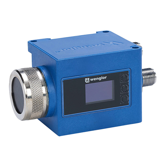
Page 12: Control Panel
20 = Enter Button 22 = Up Button 23 = Down Button 60 = Display 3.6. Scope of Delivery • OPT2022 • Connecting nut • Quickstart 4. Transport and Storage 4.1. Transport Upon receipt of shipment, inspect the goods for damage in transit. In the case of damage, conditionally accept the package and notify the manufacturer of the damage. -
Page 13: Installation And Electrical Connection
• Remove the protective cap from the sensor before attaching fiber-optic cables. • Protect fiber-optic cables from mechanical influences! 1 Color Sensor 3 adapter No. 1 2 wenglor® Fiber Optic 4 Sleeve Nut ATTENTION! Risk of property damage in case of improper installation! The product may be damaged. -
Page 14: Diagnostics
Risk of personal injury or property damage in case of non-compliance! The system’s safety function is disabled. Personal injury and damage to equipment. – Conduct in case of fault as specified. 6. Overview of Functions 6.1. Default Settings OPT2022 Pin function Switching Output Switching Output Switching Output... -
Page 15: Function Definitions
Back: One level up in the menu. 7 Run: Change to the display mode ATTENTION! Risk of property damage if sharp objects are used! The keys may be damaged. – Do not use sharp objects in order to enter settings. OPT2022... - Page 16 The sensor configuration menu is set-up as follows: Switch Pin Function Error Contaminate Depends on Pin Function: Configure During Switching Output A1 Switch T Windows <T> for Teach-In A2 Switch T Sample Teach OK/NOK Tolerance Tolerance … ...
-
Page 17: Settings
Switching Output – – Switched Not switched Error Output – – No signal Contamination – – Signal too low Output Signal Strength No signal Signal too low Signal too high temperature too temperature too temperature – high OPT2022... -
Page 18: Pin Function
7.3. Pin function The Pin function is used to determine the function of pins A1, A2, A3, A4, A5, A6, A7, A8, A9, A10, A11 and/or A12 since the pins may be used for different functions. Function Description Configuration of Pin A1,2, 3, 4, 5, 7, 6, 8, 9, 10, 11 and/or 12 ... -
Page 19: Tolerance
(supply) and the output. If the sensor switches, the output is con- nected with the negative pole via an electric switch. Push-pull: Push-pull output. Acts like an electronic switch which optionally switches the output to the positive pole or the negative pole. OPT2022... -
Page 20: Switching Thresholds
7.7. Switching Thresholds The switching thresholds can be set manually via IO-Link. Switching points: The following switching points are calculated on the basis of the measured value during Teach-In: Hoff Measurement Loff Hoff = Hon + Hysteresis Hon = Hue value + window size Lon = Hue value –... -
Page 21: Display
Select display mode Digital Digital: The condition of each output is indicated on the display. Bar Graph Bar Graph: The ROYGBV color spaces / shares of the object are Back indicated in a bar graph. Run OPT2022... -
Page 22: Interfaces
Furthermore, wenglor herewith explicitly informs the user that these operating instruc- tions are only a general description of technical procedures whose implementation may not be suitable in all cases as described in this document. -
Page 23: Appendix
12.2. Change Index, Operating Instructions Associated Version Date Description/Change Software 1.0.0 17.11.16 Initial version of the operating instructions Firmware: 1.0.0 12.3. EU Declaration of Conformity The EU declaration of conformity can be found on our website at www.wenglor.com in download area. OPT2022...
Need help?
Do you have a question about the OPT2022 and is the answer not in the manual?
Questions and answers