
Related Manuals for Wenglor ODX202


Summary of Contents for Wenglor ODX202
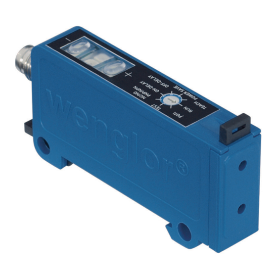
- Page 1 ODX202 Fiber Optic Cable Sensor Operating Instructions Available as PDF only Status: 10.10.2016...
-
Page 2: Table Of Contents
Table of Content 1. Proper Use 2. Safety Precautions 3. Product Features 3.1. Connection Diagrams 3.2. Housing Dimensions 3.3. EC Declaration of Conformity 3.4. Technical Data 3.5. Contamination Warning 3.6. Contamination Output 3.7. Complementary Products (see catalog) 3.8. Control Panel 3.9. -
Page 3: Proper Use
1. Proper Use This wenglor product has to be used according to the following functional principle: Fiber Optic Cable Sensors Both plastic fiber optic cables and glass fiber optic cables can be connected to fiber optic cable sensors. Uni- versal reflex sensors can be used both with and without fiber optic cables. Fiber optic cable sensors analyze the light reflected by the object. -
Page 4: Housing Dimensions
1 = Transmitter Diode 2 = Receiver Diode 3.3. EC Declaration of Conformity The EC declaration of conformity can be found on our website at www.wenglor.com in download area. Any additional standards which are applicable for the given application must be observed. RoHS... -
Page 5: Technical Data
DIN-Rail mounting 35 mm 3.5. Contamination Warning The contamination warning (included with all ODX202 types) is indicated by means of a blinking red LED (02) (with rotary switch in the Run position). 3.6. Contamination Output The contamination output (included with ODX202P0107) functions as a normally closed contact and is switched off if the Sensor is operated within an unreliable range. -
Page 6: Complementary Products (See Catalog)
3.7. Complementary Products (see catalog) wenglor offers Connection Technology for field wiring. Suiting Connection Technology No. Glass Fiber Optic Cable Plastic Fiber Optic Cable 3.8. Control Panel 24 01 02 TEST NC/NO POTI PNP/NPN ON-DELAY TEACH OFF-DELAY POWER SAVE 01 = Switching Status Indicator... -
Page 7: Side Mounting
fig.1 Mounting of the Sensor to a DIN rail 3.9.2. Side mounting Side mounting a unit: Secure the Sensor with screws (M4) through the mounting holes. fig. 2 Side mounting of the Sensor 3.9.3. Connecting the plastic fibre-optic cable •... -
Page 8: Adjustment
4. Adjustment 4.1. On-Delay and Off-Delay fig. 4 On-Delay and Off-Delay Adjusting On- and Off-Delay with rotary selector switch (07) set to On-Delay or Off-Delay Delay Gelbe Status-LED ( 02 ) Minus Button (25) Plus Button (24) 0 ms lighted up not lighted up not lighted up 10 ms... -
Page 9: Selecting Normally Closed Or Normally Open Function (Nc/No)
4.2. Selecting normally closed or normally open function (NC/NO) TEST NC/NO POTI PNP/NPN ON-DELAY TEACH OFF-DELAY POWER SAVE •Set rotary selector switch (07) to NC/NO PNP/NPN • Activate the plus button (24) è NC is selected (normally closed/dark switching) è Plus button (24) lights up •... -
Page 10: Setting Switching Distance With The Potentiometer
4.4. Setting Switching Distance with the potentiometer TEST NC/NO POTI PNP/NPN ON-DELAY TEACH OFF-DELAY POWER SAVE • Set rotary selector switch (07) to Poti • Activate the plus button (24) è Switching Distance is increased • Activate the minus button (25) è... -
Page 11: Minimal Teach-In
No object (light barrier is unobstructed) fig. 5 Scanning mode during Teach-In fig. 6 Barrier mode during Teach-In 4.5.2. Minimal Teach-In • Set rotary selector switch (07) to Teach • Align spot to object • Activate the minus button (25) è... -
Page 12: Dynamic Teach-In (Teach-In With Moving Objects)
4.5.3. Dynamic Teach-In (Teach-In with moving objects) • Set rotary selector switch (07) to Teach • Press and hold the plus button (24) until (24) blinks at the plus button (after approx. 5 sec) è The Sensor is now in the recording mode and acquires minimum and maximum incoming light signals •... -
Page 13: Two-Point Teach-In
4.5.4. Two-point Teach-In • Set rotary selector switch (07) to Teach • Align the spot to object A • Activate the plus button (24) è Plus button (24) lights up • Align the spot to object B • Activate the minus button (25) è... -
Page 14: Selecting The Run Function
External Minimal Teach-In (see also fig. 7 and 8) Initialise minimal Teach-In: Set rotary selector switch to Teach, press the minus button twice, set rotary selector switch to Run) • Set rotary selector switch (07) to Run • Apply 10 V to 30 V to the Teach-In input (in relation to minus pole, for at least 0.3 sec) è... -
Page 15: Selecting The Light Pulse Frequency
4.7.2. Selecting the Light pulse frequency Display of actual Light pulse frequency: • Set rotary selector switch (07) to Power Save è Plus button (24) lights up: With the rotary selector switch set to Run, the light pulse frequency is 7.58 kHz. è... -
Page 16: Energy Saving Mode
• It is advisable to clean the lens and the display, and to check the plug connections at regular intervals. • Do not clean with solvents or cleansers which could damage the device. 6. Proper Disposal wenglor sensoric gmbh does not accept the return of unusable or irreparable products. Respectively valid national waste disposal regulations apply to product disposal.
Need help?
Do you have a question about the ODX202 and is the answer not in the manual?
Questions and answers