Ltech LT-932-OLED - DMX512 Decoder Manual
- Manual (8 pages) ,
- Manual (8 pages) ,
- Quick start manual (8 pages)
Advertisement
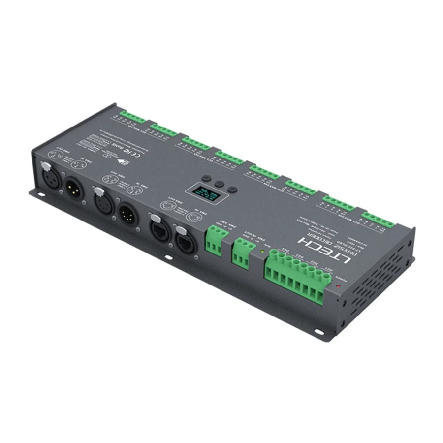
Product introduction

- Designed for Hi-power multiple channels application, 32 channels output, and Max. 3A current per channel, up to 2304W output power.
- Easy operation with OLED screen and touch buttons.
- 4 kinds of control modes available: DIM, CT, RGB, RGBW.
- 3-pin XLR, 5-pin XLR, RJ45 and green terminal DMX interface with photoelectric isolation, improve signal transmission efficiency and anti-interference ability, the green terminal also has signal amplifier function.
- With RDM remote management protocol, the operations can be completed via the RDM master console, such as parameters browsing & settings, DMX address settings, equipment recognition, etc.
- With firmware upgrade function.
- With short circuit, over current and overheat protection, as well as warning function when a fault occurs.
- With power-on state management and fast self-testing function.
- 16bit (65536 levels) / 8bit (256 levels) grey level available.
- Available in standard, linear, LOG or custom 0.1-9.9 dimming curve.


Technical specs
| Model | LT-932-OLED |
| Input signal | DMX512/RDM |
| Input voltage | 12~24Vdc |
| Current load | 3A × 32CH Max. 96A |
| Output power | (0~36W...72W) × 32CH Max. 2304W |
| DMX interfaces | 3-pin XLR, 5-pin XLR, RJ45, Green terminal |
| Control modes | DIM/CT/RGB/RGBW |
| Dimming curves | 0.1~9.9, standard, linear, LOG |
| Grey level | 8bit (256 levels) / 16bit (65536 levels) |
| Photoelectric isolation | Yes |
| Protection | Short circuit / Overheat / Over current protection, recover automatically. |
| Working temperature | -30°C~65°C |
| Dimensions | 300×122×39mm(L×W×H) |
| Package size | 313×127×41mm(L×W×H) |
| Weight (G.W.) | 1180g |
Product size

Main component description

OLED screen interface

Press "M" key, switch entries. Long press "M" key, back to main page. Press "∧" or "∨" key, parameter adjustment. Exit: back to previous page.
- DMX address settings
Press "∧" or "∨" key to set DMX address.
Range: 001~512
![]()
- PWM frequency

- Modes
Press "∧" or "∨" key to choose. Option : DIM / CT / CT2 / RGB / RGBW
![]()
- Grey scale
Press "∧" or "∨" key to choose.
Option: 8bit
16bit (choose it if the master controller supports this function)
![]()
- Dimming curves
Press "∧" or "∨" key to choose.
Option : Standard
Linear
LOG
0.1~9.9
It is recommended to use standard,
0.1-9.9 is for special requirements.
![]()
- Enhance Dimming
Press "∧" or "∨" key to choose.
Option : Std (standard)
Smo (smooth)
* It is recommended to use standard.
Smo: This option with smooth processing, realizes flicker-free dimming and smooth dynamic effects.
![]()
- Tool

* Fast self-testing function: press " ∧" or " ∨" keys simultaneously for 2-3 seconds under any page, decoder will enter self-testing function.


Wiring diagram
- Connecting LED lights:


- DMX console connection
 LT-932-OLED is equipped with 4 kinds of DMX terminals for users' selection. The following diagram takes 3-pin XLR as an example, same connecting method for the rest three: RJ45 & 5-pin XLR & green terminal (with amplifier function).
* If the recoil effect occurs because of longer signal line or bad line quality, please try to connect 0.25W 90-120Ω terminal resistor at the end of each line. - The connection diagram of 4 kinds of DMX/RDM terminals:

* Installation attentions : please reserve enough ventilation distance between decoders (>20mm), be sure not to block the vent, or it will affect lifetime of decoder for poor heat dissipation. - The connection diagram of AMP signal amplifier terminal:
* Connecting with green terminal or an extra amplifier will be needed when more than 32 decoders are connected or use overlong signal wire (as shown below). Signal amplifier should not be more than 5 times continuously.


Address setting table
| Mode | DIM | CT/CT2 | RGB | RGBW | |
| Address Quantity | 8 | 16 | 24 | 32 | |
| Resolution | 8bit | 8bit | 8bit | 8bit | |
| Channel | 1 | 001 | 001 | 001 | 001 |
| 2 | 001 | 002 | 002 | 002 | |
| 3 | 001 | 001 | 003 | 003 | |
| 4 | 001 | 002 | 003 | 004 | |
| 5 | 002 | 003 | 004 | 005 | |
| 6 | 002 | 004 | 005 | 006 | |
| 7 | 002 | 003 | 006 | 007 | |
| 8 | 002 | 004 | 006 | 008 | |
| 9 | 003 | 005 | 007 | 009 | |
| 10 | 003 | 006 | 008 | 010 | |
| 11 | 003 | 005 | 009 | 011 | |
| 12 | 003 | 006 | 009 | 012 | |
| 13 | 004 | 007 | 010 | 013 | |
| 14 | 004 | 008 | 011 | 014 | |
| 15 | 004 | 007 | 012 | 015 | |
| 16 | 004 | 008 | 012 | 016 | |
| 17 | 005 | 009 | 013 | 017 | |
| 18 | 005 | 010 | 014 | 018 | |
| 19 | 005 | 009 | 015 | 019 | |
| 20 | 005 | 010 | 015 | 020 | |
| 21 | 006 | 011 | 016 | 021 | |
| 22 | 006 | 012 | 017 | 022 | |
| 23 | 006 | 011 | 018 | 023 | |
| 24 | 006 | 012 | 018 | 024 | |
| 25 | 007 | 013 | 019 | 025 | |
| 26 | 007 | 014 | 020 | 026 | |
| 27 | 007 | 013 | 021 | 027 | |
| 28 | 007 | 014 | 021 | 028 | |
| 29 | 008 | 015 | 022 | 029 | |
| 30 | 008 | 016 | 023 | 030 | |
| 31 | 008 | 015 | 024 | 031 | |
| 32 | 008 | 016 | 024 | 032 | |
| Mode | DIM | CT/CT2 | RGB | RGBW | |
| Address Quantity | 16 | 32 | 48 | 64 | |
| Resolution | 16bit | 16bit | 16bit | 16bit | |
| Channel | 1 | 001 002 | 001 002 | 001 002 | 001 002 |
| 2 | 001 002 | 003 004 | 003 004 | 003 004 | |
| 3 | 001 002 | 001 002 | 005 006 | 005 006 | |
| 4 | 001 002 | 003 004 | 005 006 | 007 008 | |
| 5 | 003 004 | 005 006 | 007 008 | 009 010 | |
| 6 | 003 004 | 007 008 | 009 010 | 011 012 | |
| 7 | 003 004 | 005 006 | 011 012 | 013 014 | |
| 8 | 003 004 | 007 008 | 011 012 | 015 016 | |
| 9 | 005 006 | 009 010 | 013 014 | 017 018 | |
| 10 | 005 006 | 011 012 | 015 016 | 019 020 | |
| 11 | 005 006 | 009 010 | 017 018 | 021 022 | |
| 12 | 005 006 | 011 012 | 017 018 | 023 024 | |
| 13 | 007 008 | 013 014 | 019 020 | 025 026 | |
| 14 | 007 008 | 015 016 | 021 022 | 027 028 | |
| 15 | 007 008 | 013 014 | 023 024 | 029 030 | |
| 16 | 007 008 | 015 016 | 023 024 | 031 032 | |
| 17 | 009 010 | 017 018 | 025 026 | 033 034 | |
| 18 | 009 010 | 019 020 | 027 028 | 035 036 | |
| 19 | 009 010 | 017 018 | 029 030 | 037 038 | |
| 20 | 009 010 | 019 020 | 029 030 | 039 040 | |
| 21 | 011 012 | 021 022 | 031 032 | 041 042 | |
| 22 | 011 012 | 023 024 | 033 034 | 043 044 | |
| 23 | 011 012 | 021 022 | 035 036 | 045 046 | |
| 24 | 011 012 | 023 024 | 035 036 | 047 048 | |
| 25 | 013 014 | 025 026 | 037 038 | 049 050 | |
| 26 | 013 014 | 027 028 | 039 040 | 051 052 | |
| 27 | 013 014 | 025 026 | 041 042 | 053 054 | |
| 28 | 013 014 | 027 028 | 041 042 | 055 056 | |
| 29 | 015 016 | 029 030 | 043 044 | 057 058 | |
| 30 | 015 016 | 031 032 | 045 046 | 059 060 | |
| 31 | 015 016 | 029 030 | 047 048 | 061 062 | |
| 32 | 015 016 | 031 032 | 047 048 | 063 064 | |
* When you select CT2, the DMX address represents brightness, color temperature and constant power output respectively.
Work with RDM editor
LT-932-OLED can work with LTECH RDM editor (Model: WiFi-RDM01) to realize changing the parameters and firmware upgrade by long-range setting, wiring diagram as below:


RDM editor App interface instructions
Download the App, setting the LT-932-OLED parameters (frequency, bit, curve, modes, dimming range, screensaver, etc.) after well connecting the RDM editor, more details, please check the manual of WiFi-RDM01. Well installation of products first, then working with WiFi -RDM01 to realize setting parameters and firmware upgrade by App.

- Click"Add", edit the address in corresponding boxю
- Click"ID", get more product details.
- Click"
![]() ", enter edited interfaceю
", enter edited interfaceю - Click"No.", issue the recognizing command.

Supporting WiFi-RDM01 upgrade and DMX driver upgrade.
* This manual is subject to changes without further notice. Product functions depend on the goods. Please feel free to contact our official distributors if you have any question.


Documents / Resources
References
Download manual
Here you can download full pdf version of manual, it may contain additional safety instructions, warranty information, FCC rules, etc.
Advertisement


Need help?
Do you have a question about the LT-932-OLED and is the answer not in the manual?
Questions and answers