
Related Manuals for Ltech LT-912-OLED


Summary of Contents for Ltech LT-912-OLED
- Page 1 LT-912-OLED OLED display 8 bit / 16 bit Photoelectric E500585 3 kinds of DMX interfaces isolation Dimming curve: 0.1~9.9 CHANNELS Short circuit / Over current / Overheat protection www.ltech-led.com...
-
Page 2: Product Introduction
Product introduction 1. Designed for Hi-power multiple channels application, 12 channels output, and Max. 4A current per channel, up to 1152W output power. 2. Easy operation with OLED screen and touch buttons. 3. 3 kinds of optional modes available: DIM, CT, RGB. -
Page 3: Technical Specs
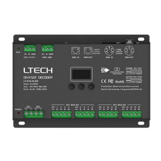
Technical specs LT-912-OLED Model : DMX512/RDM Input signal : 12~24Vdc Input voltage : 4A × 12CH Max. 48A Current load : (0~48W...96W) × 12CH Max. 1152W Output power : 5-pin XLR, RJ45, green terminal DMX interfaces : DIM/CT/RGB Control modes : 0.1~9.9, standard, linear, LOG... - Page 4 Main component description OLED screen Signal indicator Power indicator Powered Powered Max. 24A Max. 24A Green terminals RJ45 5-pin XLR (with signal amplifier function) DMX/RDM input & output 12-24V Green terminals Power input LED lamp connection...
- Page 5 OLED screen interface Press "M" key, switch entries. Long press “M” key, back to main page. Press "∧" or “∨" key, parameter adjustment. Exit back to previous page. Press “∧" or “∨" key to set DMX address. 1. DMX address...
- Page 6 Press “∧" or “∨" key to choose. 6. Enhance DMX: 001 Hz: High dimming Mode: RGB 8bit Option : Std (standard) Curve: Standard Smo (smooth) Dim: Smo TOOL&v It is recommended to use standard. Smo: This option with smooth processing, realizes flicker-free dimming and smooth dynamic effects.
-
Page 7: Wiring Diagram
Wiring diagram 1. Connecting LED lights: DMX/RDM signal DMX/RDM signal LT-912-OLED Output port 12-24Vdc (Wiring method on P7) Power to Power to 1, 2 LEDS 3, 4 LEDS LED driver LEDs DMX/RDM signal DMX/RDM signal LT-912-OLED 12-24Vdc Power to... - Page 8 RGB LEDs RGB mode 2. DMX console onnection LT-912-OLED is equipped with 3 kinds of DMX terminals for users’ selection. The following diagram takes 5-pin XLR as an example, same connecting method for the rest two: RJ45 & green terminal (with amplifier function).
- Page 9 3. The connection diagram of 3 kinds of DMX/RDM terminals: Resistor 5-pin XLR terminal connected LT-912-OLED LT-912-OLED LT-912-OLED in parallel Resistor Green terminal terminal LT-912-OLED LT-912-OLED LT-912-OLED connected in parallel Resistor RJ45 Vent terminal connected LT-912-OLED LT-912-OLED LT-912-OLED in parallel These 3 terminals can be connected Installation distance >...
- Page 10 Address setting table Mode CT/CT2 Mode CT/CT2 Address Address Quantity Quantity Resolution 8bit 8bit 8bit Resolution 16bit 16bit 16bit Channel Channel When you select CT2, the DMX address represents brightness , color temperature and constant power output respectively.
- Page 11 Work with RDM editor LT-912-OLED can work with LTECH RDM editor (Model: WiFi-RDM01) to realize changing the parameters by long-range setting, wiring diagram as below: 5-24Vdc power input WIFI-RDM01 Support portable power supplies … … … LT-912-OLED LT-912-OLED LT-912-OLED...
- Page 12 RDM editor App interface instruction Download the App, setting the LT-912-OLED parameters (frequency, bit, curve, modes, dimming range, screensaver, etc.) after well connecting the RDM editor, more details, please check the manual of WiFi-RDM01. Well installation of products first, then working with WiFi -RDM01 to realize setting parameters and firmware upgrade by App.
Need help?
Do you have a question about the LT-912-OLED and is the answer not in the manual?
Questions and answers