
Related Manuals for Festo CP Factory


Summary of Contents for Festo CP Factory
- Page 1 8152450 Labeling CP Factory/CP Lab Original operating instructions Festo Didactic 8152450 en 10/2022...
- Page 2 10/2022 Authors: Schober, Weiss Layout: Frank Ebel File Name: CP-AM-LABEL-GB-8152450-A001.doc © Festo Didactic SE, Rechbergstr. 3, 73770 Denkendorf, Germany, 2022 +49 711 3467-0 www.festo-didactic.com +49 711 34754-88500 did@festo.com Original operating instructions © 2022 all rights reserved to Festo Didactic SE.
-
Page 3: Table Of Contents
6.6 Electrical Connections .......................... 40 6.6.1 Overview ............................40 6.6.2 I/O Box XD1 ........................... 41 7 Commissioning ............................42 7.1 Workplace ............................42 7.2 Visual Inspection ..........................43 7.3 Safety Regulations ..........................43 7.4 Assembly .............................. 44 © Festo Didactic 8065842 en... - Page 4 7.4.3 Pneumatic connection from application modules to basic module CP Lab Conveyor (option – not available at all application modules) ...................... 50 7.4.4 Assembly of an CP application module to a CP Factory basic module ........... 51 7.4.5 Connecting the CP application module electrically to the CP Factory basic module ...... 54 7.4.6 Pneumatic connection from application modules to CP Factory basic module ......
-
Page 5: Safety Instructions
In cases where more than one hazard level applies, the safety note with the highest hazard level will be shown. A safety note may concern both personal injury and property damage. Hazards that will only result in property damage are indicated with the word "Note". © Festo Didactic 8065842 en... -
Page 6: Pictograms
Switch off the device and unplug the connection for power supply from the plug socket before commencing installation, repair, maintenance or cleaning work. Warning – hand injuries Warning – lifting heavy loads Information and/or references to other documentation © Festo Didactic 8065842 en... -
Page 7: General Prerequisites For Installing The Product
1.3 General prerequisites for installing the product • Festo Didactic products must only be used for the applications specified in their respective operating instructions. Products or components supplied by other manufacturers must only be used if recommended or approved by Festo. -
Page 8: Intended Use
Festo Didactic due to malicious intent or gross negligence. All extensions and accessories must be approved by Festo Didactic, and are only permitted for use for their intended purpose. -
Page 9: For Your Safety
Knowledge of the basic safety instructions and safety regulations is a fundamental prerequisite for safe handling and trouble-free operation of Festo Didactic components and systems. These operating instructions include the most important instructions for safe use of the components and systems. -
Page 10: Qualified Persons
All persons who have been entrusted to work with the components and systems undertake to complete the following steps before beginning work: • Read the chapter concerning safety and the warnings in these operating instructions • Familiarize themselves with the basic regulations regarding occupational safety and accident prevention © Festo Didactic 8065842 en... -
Page 11: Basic Safety Instructions
Devices can reach high temperatures during operation, as a result of which they can cause burns if touched. • Measures to take when maintenance is required. – Allow the device to cool off before commencing work. – Use suitable personal protective clothing, e.g. safety safety gloves. © Festo Didactic 8065842 en... -
Page 12: Electrical Components
If a device i connected to an unsuitable power supply, this can cause components to overheat, leading to a breakout of fire. – Always use limited power supplies (LPSs) for all the connections and terminals on the electronics modules. © Festo Didactic 8065842 en... - Page 13 Safe operation of the device is not possible in the event of any of the following circumstances: – Visible damage – Malfunction – Inappropriate storage – Incorrect transport Switch off the power supply immediately. • Protect the device to prevent it from being restarted accidentally. © Festo Didactic 8065842 en...
-
Page 14: Pneumatic Components
Do not attempt to seal or plug pneumatic tubing or plug connectors with your hands or fingers. • Check the condition of the condensate in the service unit regularly. If necessary, drain the condensate and dispose of it properly. © Festo Didactic 8065842 en... - Page 15 – All of the exhaust ports on the components included in the equipment set are equipped with mufflers. Do not remove these mufflers. © Festo Didactic 8065842 en...
-
Page 16: Guarantee And Liability For Application Examples
Furthermore, Festo's guidelines on suitable security measures should be observed. Festo products and solutions are constantly being developed further in order to make them more secure. Festo strongly recommends that customers install product updates as soon as they become available and always use the latest versions of its products. -
Page 17: Additional Safety Instructions
The device is not equipped with a built-in circuit unless otherwise specified in the technical data. WARNING • This product is designed for use in industrial environments, and may cause malfunctions if used in domestic or small commercial environments. © Festo Didactic 8065842 en... -
Page 18: Guarantee And Liability
Disasters resulting from the influence of foreign bodies and acts of God • Dust generated during construction work must be kept away from the system (use coverings). See the Environmental Requirements section (contamination level) for more details. © Festo Didactic 8065842 en... -
Page 19: Transport
Station contains delicate components! – Take care not to shake during transportation • The station is only permitted for installation on solid, non-vibrating surfaces. – Make sure that the ground underneath the station has sufficient load-bearing capacity. © Festo Didactic 8065842 en... -
Page 20: Name Plates
Technical data Technical data Technical data Safety note Manufacturer address UK importer address Country of origin Internet address service portal CE Mark UKCA mark Warning mark Symbol read manual WEEE Marking QR Code (Type-and serial number) © Festo Didactic 8065842 en... -
Page 21: Ce Declaration Of Conformity
Fundamental safety instructions 4.11 CE Declaration of Conformity © Festo Didactic 8065842 en... - Page 22 Fundamental safety instructions © Festo Didactic 8065842 en...
- Page 23 Fundamental safety instructions © Festo Didactic 8065842 en...
-
Page 24: General Product Safety
– Product safety can no longer be guaranteed by the operator. – In this case, the manufacturer's CE declaration of conformity expires. The operator must re-evaluate the safety and determine the CE conformity. © Festo Didactic 8065842 en... -
Page 25: Protective Devices
The individual components, such as the power supplies and the controllers, possess built-in safety functions such as short-circuit protection, overcurrent protection, overvoltage protection and thermal monitoring. If necessary, consult the instruction manual for the device in question for more information. © Festo Didactic 8065842 en... -
Page 26: Technical Data
CE marking in accordance with: Machinery Directive EMC Directive RoHS Directive EMC environment Industrial environment, Class A (in acc. with EN 55011) Measurements Length 434 mm Width 198 mm Height 766 mm Weight Approx 11 kg Subject to change © Festo Didactic 8065842 en... - Page 27 Technical data Illustration similar © Festo Didactic 8065842 en...
-
Page 28: Design And Function
It is not permitted to grip onto or under the feet when handling the machine, as there is an increased risk of hands or feet getting crushed or trapped in these areas. – When setting down the station, make sure no persons have their feet under the machine's feet. © Festo Didactic 8065842 en... - Page 29 – Check that all the profile connectors are seated correctly using a size 4 – 6 Allen key. Unavoidable vibrations can loosen the connectors during transport. © Festo Didactic 8065842 en...
-
Page 30: Overview Of The System
6.2 Overview of the System CP Lab Conveyor, CP Factory Linear, CP Factory Shunt and CP Factory Bypass are called basic modules. If an application module, e.g. the CP Application Module muscle press is attached to a basic module, it becomes a station. -
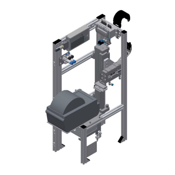
Page 31: The Application Module Labeling
Illustration similar Position Designation I/O module Pressure control valve for vacuum and Z-axis (approx. 2 bar) Label printer Sensor workpiece detection front side Valve terminal Cylinder Z-axis Mini slide X-axis Connection plate / Vacuum nozzle © Festo Didactic 8065842 en... -
Page 32: Electrics
Part number Res.Ident Proximity sensor SMT-8M-A-PS-24V-E-2,5-OE 574335 Z-axis upper end position Proximity sensor SMT-8M-A-PS-24V-E-2,5-OE 574335 X-axis pick up label position Proximity sensor SMT-8M-A-PS-24V-E-2,5-OE 574335 X-axis back end position Proximity sensor SMT-8M-A-PS-24V-E-2,5-OE 574335 Z-axis lower end position © Festo Didactic 8065842 en... - Page 33 Design and function Illustration similar Position Description Part number Res.Ident Light guide unit D: SOEG-L-Q30-P-A-S-2L 8127556 Workpiece available Light guide SOOC-TB-M4-2-R25 552812 Workpiece available © Festo Didactic 8065842 en...
- Page 34 Design and function I/O module XD1 part number 8027412 – illustration similar Zebra label printer ZD410 - PH1 / part number ZEB.ZD410 – illustration similar © Festo Didactic 8065842 en...
-
Page 35: Pneumatic
Move out X-axis Valve CPVSC1-K-M5C 548899 MB 3 Move Z-axis upwards Valve CPVSC1-K-M5C 548899 MB 4 Move Z-axis downwards Plate CPVSC1-SP-M5 527532 XL10 Valve CPVSC1-K-M5C 548899 MB 6 Switch on vacuum Valve CPVSC1-K-M5C 548899 MB 7 Blow © Festo Didactic 8065842 en... - Page 36 GRLA-M5-QS-4-D with HGL-M5-B 193138 / 530029 Guiding drive DFM-12-50-P-A-GF 170829 one-way flow control valve GRLA-M5-QS-4-D 193138 QS-connection plate / vacuum nozzle QSM-M5-3-I 153313 one-way flow control valve GRLA-M5-QS-4-D 193138 Cylinder Z-axis DGC-18-200-GF-PPV-A 8153144 © Festo Didactic 8065842 en...
- Page 37 Design and function Illustration similar Position Description Part number Pressure regulator for vacuum VRPA-CM-Q6-E 8086004 Pressure regulator for Z-axis (approx. 2 bar) VRPA-CM-Q6-E 8086004 vacuum generator VN-05-H-T4-PQ2-VQ2-O1-P 536796 Pressure control valve for blow pipe GRLZ-M5-QS-3-LF-C 175055 © Festo Didactic 8065842 en...
-
Page 38: Function
All connections have been established properly. Starting position Illustration similar 1. The Z-axis must be in its upper end position 2. The X-axis must be in its rear end position 3. The label printer must be switched on © Festo Didactic 8065842 en... - Page 39 7. The X axis returns 8. Z-axis moves downwards 9. The label is applied to the workpiece 10. The Z-axis moves up again and is clamped 11. The carrier is released again and leaves the application module © Festo Didactic 8065842 en...
-
Page 40: Electrical Connections
I/O terminal (2) on the electrical board of the module. The example refers to the connection to a basic module linear, it is possible that the terminal names of the I/O terminal deviate when connected to another module. Illustration similar © Festo Didactic 8065842 en... -
Page 41: I/O Box Xd1
XMA2 / XK: O3 XMA2:XS4 Open cylinder clamp unit XMA2 / XK: O4 XMA2:XS5 Vacuum switch on XMA2 / XK: O5 XMA2:XS6 XMA2:XS7 Blow XMA2 / XK: O6 Switch cutter motor on XMA2 / XK: O7 XMA2:XS8 © Festo Didactic 8065842 en... -
Page 42: Commissioning
• a CP Application Module • a basic module CP Factory or a basic module CP Lab Conveyor for the installation of the CP Application Module • a SysLink cable for the connection between the I/O terminal of the CP Application Module and the basic module CP Factory •... -
Page 43: Visual Inspection
The technical condition – mechanically and electrically – of the CP Application Module is perfect. • The CP Application Module is used in accordance with the regulations. • The operating instructions have been read and understood. • All safety devices are available and active. © Festo Didactic 8065842 en... -
Page 44: Assembly
The assembly process is explained in the following chapter as an example. The displayed dimension is an approximation, it is possible that a fine adjustment is necessary for error-free processing. Example distance between application module and stopper / illustration similar © Festo Didactic 8065842 en... -
Page 45: Assembly Of An Cp Application Module To Basic Module Cp Lab Conveyor
Then you have to position the slot nuts (2) approximately to the distance of the vertical cross profiles of the CP application module. Positioning slot nuts / illustration similar Position Description back cross profile slot nut Inner slot (back cross profile) Inner slot (front cross profile) front cross profile © Festo Didactic 8065842 en... - Page 46 NOTE Use Allen keys for lateral adjustment of the slot nuts. How to put on the CP application module / illustration similar Position Description CP application module: mounting bracket slot nut © Festo Didactic 8065842 en...
- Page 47 Now tighten the raised head screws. • Then put the black covers onto the mounting brackets. Tightening the CP application module / illustration similar Position Description CP application module: mounting bracket with cover basic module CP Lab Conveyor: cross profile © Festo Didactic 8065842 en...
-
Page 48: Connecting The Cp Application Module Electrically To Basic Module Cp Lab Conveyor
CP Lab Conveyor: control or decentralized periphery CP application module: I/O terminal (+BG-XD1) CP application module: analogue terminal (+BG-XD2A) connecting cable with a SysLink-plug (SysLink-cable) basic module CP Lab Conveyor: board at the back (+G1-XZ2) © Festo Didactic 8065842 en... - Page 49 CP Lab Conveyor: control or decentralized periphery CP application module: I/O terminal (+BG-XD1) CP application module: analogue terminal (+BG-XD2A) connecting cable with a SysLink-plug (SysLink-cable) basic module CP Lab Conveyor: board at the back (+G1-XZ2) © Festo Didactic 8065842 en...
-
Page 50: Pneumatic Connection From Application Modules To Basic Module Cp Lab Conveyor (Option - Not Available At All Application Modules)
4) is simply inserted into the QS connector. The supply line (5) is plugged into the T-plug (3) The CP Lab Band is also supplied with a T-connector (4). Pneumatically connect application module / illustration similar © Festo Didactic 8065842 en... -
Page 51: Assembly Of An Cp Application Module To A Cp Factory Basic Module
Commissioning 7.4.4 Assembly of an CP application module to a CP Factory basic module NOTE The procedure for installing a CP application module on a basic module is identical for all basic modules. The following example is an example for all basic modules and applications. - Page 52 Attaching the application module to the CP Factory basic module • Put the CP application module on the CP Factory basic module. • Position the slot nuts (2) underneath the mounting brackets (1) of the CP application module so that the internal threads of the slot nuts are visible underneath the elongated holes of the mounting brackets.
- Page 53 • Use raised head screws M5x8, in order to connect the mounting brackets (1) of the CP application module Measuring, at first loosely, with the cross profiles (2) of the CP Factory basic module. • After setting all raised head screws, you can still move the CP application module to the position required.
-
Page 54: Connecting The Cp Application Module Electrically To The Cp Factory Basic Module
D-Sub-interface for analogue signals (option – not available at all CP application modules) The CP application module produces two analogue output signals with the distance sensors. These are set on the analogue terminal and have to be connected with the analogue inputs of the CP Factory basic module: •... -
Page 55: Pneumatic Connection From Application Modules To Cp Factory Basic Module
Commissioning 7.4.6 Pneumatic connection from application modules to CP Factory basic module The pneumatic connection is based on the principle of the following sketch. The application module is connected from the valve (terminal) to the shut-off valve (3) on the conveyor belt. -
Page 56: Adjusting The Sensors
7.5.1 Through-beam sensor (Workpiece detection) Illustration similar Position Designation sensor and light deflection/ 8127556 (D: SOEG-L-Q30-P-A-S-2L) Sensor socket with sensor 552812 (SOOC-TB-M4-2-R25) and adapter lens 552830 (SASF-L1-LA-M2) Sensor socket with sensor 552812 (SOOC-TB-M4-2-R25) and adapter lens 552830 (SASF-L1-LA-M2) © Festo Didactic 8065842 en... - Page 57 You have to do this with all 3 light barriers. Please pay special attention to the corresponding function. Documents Data sheets / Operating instructions Fibre-optic unit D: SOEG_L (8127556) through-beam sensor SOOC-TB-M4-2-R25 (552812) Adapter lens SASF-L1-LA-M2 (552830) © Festo Didactic 8065842 en...
-
Page 58: Proximity Switch (Z And X-Axis Cylinder)
Z-axis in lower position / 574335 (SMT-8M-A-PS-24V-E-2,5-OE) The proximity switches are used for checking the end position of the cylinder for the Z and X-axis. The proximity switches react to a permanent magnet on the piston of the cylinder. © Festo Didactic 8065842 en... - Page 59 5. Tighten the locking screw of the proximity switch with an Allen key SW1.3. 6. Please check the position of the proximity switch by repeated test runs of the cylinder. Documents • Data sheets / operating instructions Proximity switch 574335 (SMT-8M-A-PS-24V-E-2,5-OE) © Festo Didactic 8065842 en...
-
Page 60: Vacuum Suction Nozzle
7.5.3 Vacuum suction nozzle Illustration similar Position Description Vacuum suction nozzle / 536796 (VN-05-H-T4-PQ2-VQ2-O1-P) The vacuum suction nozzle sucks the label onto the adapter plate - a safe transport of the label is thus ensured. © Festo Didactic 8065842 en... - Page 61 (SP = ½ (TP1 + TP2)). With VN -...- O2-P the higher Teach pressure becomes the switching pressure. Check the VN -...- P as desired in a test run with alternating pressure. The LED is illuminated parallel to the programmed switching behavior © Festo Didactic 8065842 en...
-
Page 62: Adjusting The One-Way Flow Control Valves
One way flow control valve 175055 (GRLZ-M5-QS-3-LF-C) for blowpipe (for determining the flow rate) One-way flow control valve 193138 (GRLA-M5-QS-4-D) for Z-axis cylinder One-way flow control valve 193138 (GRLA-M5-QS-4-D) for X-axis cylinder One-way flow control valve 193138 (GRLA-M5-QS-4-D) for X-axis cylinder © Festo Didactic 8065842 en... - Page 63 2. Start a test run. 3. Turn on the one-way flow control valves slowly until the required piston speed has been reached. Documents • Data sheets One-way flow control valve 193138 (GRLA-M5-QS-4-D) One-way flow control valve 175055 (GRLZ-M5-QS-3-LF-C) © Festo Didactic 8065842 en...
-
Page 64: Adjusting The Pressure Regulator
Commissioning 7.7 Adjusting the pressure regulator Pressure regulator / Illustration similar Position Description Pressure regulator 8086004 (VRPA-CM-Q6-E) for vacuum Pressure regulator 8086004 (VRPA-CM-Q6-E) for Z-axis © Festo Didactic 8065842 en... - Page 65 To secure the screw, tighten the knurled screw to lock it. 2. Start a test run, it should be possible to stop the axes by hand easily. Documents • Data sheets Pressure regulator 8086004 (VRPA-CM-Q6-E) © Festo Didactic 8065842 en...
-
Page 66: Operation
CP-Factory System can be operated. Own operating concepts or external controls are also possible. If the application module is mounted on a CP Lab or a CP Factory basic module, the general operation for this is described in the manuals of the CP Lab or CP Factory system. All application-specific information is described in this manual for the application module. - Page 67 Operation 2. Then click on Setup, setup mode is active. 3. Change to Setup mode page. © Festo Didactic 8065842 en...
- Page 68 Operation 4. Choose application © Festo Didactic 8065842 en...
- Page 69 PH_BG6: Switch PH_BG6 display (lights up green when vacuum is on and label is sucked) Switch on cutter motor switch on button: switch on cutter motor (actor PH_MB8 is activated, lights up blue if active) Cut label (optional order at label printer) © Festo Didactic 8065842 en...
- Page 70 #1 – Is the value for the variable 1 - see parameter #2 – Is the value for the variable 2 - see parameter #Q – Is the value for the QR String 1 - see parameter - only in MES Mode available © Festo Didactic 8065842 en...
- Page 71 In setup mode, the variable 1 can be edited, otherwise it is used to display the current variable 1 Variable 2: In setup mode, the variable 2 can be edited, otherwise it is used to display the current variable 2 © Festo Didactic 8065842 en...
-
Page 72: Transitions Of The Application Module
Operation 8.2 Transitions of the application module The transitions are located in the Parameters submenu The transitions can be displayed or changed here. How the transitions are processed is described in the CP-Lab conveyor manual. © Festo Didactic 8065842 en... -
Page 73: Process Of The Application Module
Operation 8.3 Process of the application module There is no process page available on the HMI for this application module. © Festo Didactic 8065842 en... -
Page 74: Flow Chart
Create return value for failed sensor check T25-T_SensFailDn Wait for Return Code <>0 Jump back to step 2 RESET T26-T_Reset Wait for reset Start Wait for reset trigger and reset condition valid (reset mode active and not inital position) © Festo Didactic 8065842 en... - Page 75 Wait for Z-Axis in upper position, wait for BG3 Suction plate is occupied T22-T_SuctOccpd Wait for suction plate is occupied, wait for BG6 S21-S_SuctOccpd2 Suction plate occupied, create return value T23-T_SuctOccpd2 Wait for Retun Code <>0 Jump back to step 2 © Festo Didactic 8065842 en...
- Page 76 Wait for X-Axis retracted and Z-Axis in upper position S12-S_MovDwnPos Lower Z-axis, set MB4, reset MB3 T12-T_MovDwnPos Wait for Z-Axis in lower position, wati for BG4 S13-S_WaitPos Wait step for placing label on part T13-T_WaitPos Wait for 500ms © Festo Didactic 8065842 en...
- Page 77 Wait 500ms for label placed and suction plate is not free, wait for BP6 S20-S_LablNotPlad2 Label has not been placed, switch off vacuum, create return value T21_LablNotPlacd2 Wait for 100ms Jump back to step 2 © Festo Didactic 8065842 en...
- Page 78 Reset: Ventilate cylinder chambers of raising and lowering Z-axis, set MB3, set MB4 S29-S_ResClampOpen Reset: Ventilate cylinder chambers of raising and lowering Z-axis, set MB3, set MB4 T35-T_WaitClampOpen Wait for clamp opened, wait for 300ms Jump back to step 24 © Festo Didactic 8065842 en...
- Page 79 Wait for Z-Axis not in upper and not in lower position, wait for not BG3 and not BG4 S28-S_ResZBetween Reset: Ventilate cylinder chambers of raising and lowering Z-axis, set MB3, set MB4 T34-T_WaitBetween Wait until chambers are filled, wait 300ms Jump back to step 24 © Festo Didactic 8065842 en...
-
Page 80: Parameter (Label)
Parameter-No. Description File-No. 0: Not defined (empty label is printed) 1: Frame with ONo, OPos and Festo-Logo 2: Frame with ONo, OPos without Festo-Logo 3: QR-Code Limitation: No limit to the value in the transition table Note: The file no. selects the desired image template for printing. The image template can be created via the printer's website. - Page 81 #1: The meaning from variable 1 is independent from the chosen picture template. #2: The meaning from variable 2 is independent from the chosen picture template. #Q: The same QR string then the actual parameters instead the placeholders to generate an optional QR-Code © Festo Didactic 8065842 en...
-
Page 82: Message Texts And Interactive Error Messages At The Hmi
- the program and the automatic mode are executed further - If the cause of the fault is fixed, the error is automatically acknowledged • Note - Displayed on the HMI but not processed in MES © Festo Didactic 8065842 en... -
Page 83: Message Texts
Label was not placed / sucking plate not free! (Sensor: PH_BP6); remove label! PLC: plcLabel; Instance: ErrLabelNotPlaced. LabelPrintSrv WarnPrinterOFF Printer not switched on! Please check printer! LabelPrintSrv WarnPrinterPaused Printer in break mode: Please check printer! © Festo Didactic 8065842 en... -
Page 84: Interactive Error Messages
Abort – The error status is ignored; the workpiece carrier receives the status code as shown in the input / output field next to the value displayed. This can be changed in this interactive error message window. © Festo Didactic 8065842 en... -
Page 85: Mes Operation
Check suction plate and sensor BP6. 1062 Printer not ready Switch on / check printer 1063 Printing label failed. Check printer 1064 Build up vacuum failed Check vacuum unit 5067 No workpiece on pallet detected! Check pallet / sensor BG1. © Festo Didactic 8065842 en... -
Page 86: Spare Part List
GRLA-M5-QS-4-D 193138 Cylinder Z-axis DGC-18-200-GF-PPV-A 8153144 Pressure regulator for vacuum VRPA-CM-Q6-E 8086004 Pressure regulator for Z-axis (approx. 2 bar) VRPA-CM-Q6-E 8086004 vacuum generator VN-05-H-T4-PQ2-VQ2-O1-P 536796 Pressure control valve for blow pipe GRLZ-M5-QS-3-LF-C 175055 © Festo Didactic 8065842 en... -
Page 87: Service And Cleaning
Service and cleaning 11 Service and cleaning The components and systems from Festo Didactic are maintenance-free. At regular intervals you should have checked: • the lenses of the optical sensors, fibre optics and reflectors • the active surface of the proximity switch •... -
Page 88: Further Information And Updating
Further information and updating 12 Further information and updating Further information and updates on the technical documentation of Festo Didactic components and systems can be found on the Internet at: www.ip.festo-didactic.com © Festo Didactic 8065842 en... -
Page 89: Disposal
Disposal 13 Disposal NOTE Electronic waste contains recyclable materials and must not be disposed of with the domestic waste. Bring electronic waste to a designated municipal collection point. © Festo Didactic 8065842 en... - Page 90 Disposal Festo Didactic SE Rechbergstraße 3 73770 Denkendorf Germany +49 711 3467-0 www.festo-didactic.com +49 711 34754-88500 did@festo.com © Festo Didactic 8065842 en...
Need help?
Do you have a question about the CP Factory and is the answer not in the manual?
Questions and answers