Festo CP Factory Manual
Application modules
Hide thumbs
Also See for CP Factory:
- Manual (126 pages) ,
- Original operating instructions (90 pages) ,
- Manual (39 pages)
Table of Contents

Related Manuals for Festo CP Factory


Summary of Contents for Festo CP Factory
- Page 1 8061184 Output CP Factory / CP Lab Application Modules Manual Festo Didactic 02/2019...
- Page 2 Schober, Weiss Layout: Frank Ebel File Name: CP-AM-OUT-GB-A003.doc © Festo Didactic SE, Rechbergstraße 3, 73770 Denkendorf, Germany, 2019 +49 711 3467-0 www.festo-didactic.com +49 711 34754-88500 did@festo.com Reproduction, distribution and utilisation of this document, as well as the communication of its contents to others without explicit authorisation, is prohibited.
-
Page 3: Table Of Contents
4.3.1 General notes ____________________________________________________________________ 24 4.4 The application module output __________________________________________________________ 24 4.5 Function _____________________________________________________________________________ 25 4.6 Process description ___________________________________________________________________ 25 4.7 Electrical Connections _________________________________________________________________ 26 4.7.1 I/O connections ___________________________________________________________________ 26 4.7.2 I/O Box XD1 ______________________________________________________________________ 27 © Festo Didactic Output... - Page 4 6.4 Transitions of the application module ____________________________________________________ 51 6.5 Parameter of application _______________________________________________________________ 52 7 Spare part list ____________________________________________________________________________ 53 8 Service and cleaning ______________________________________________________________________ 54 9 Further information and updating ___________________________________________________________ 55 10 Disposal _______________________________________________________________________________ 56 © Festo Didactic Output...
-
Page 5: Legal Information
Strong optical radiation. Failure to comply may result in serious personal injury. CAUTION …indicates that minor personal injury can result if proper precautions are not taken. Hot surfaces. Failure to comply may result in personal injury. © Festo Didactic Output... - Page 6 If more than one degree of danger is present, the warning notice representing the highest degree of danger will be used. A notice warning of injury to persons with a safety alert symbol may also include a warning relating to property damage. © Festo Didactic Output...
-
Page 7: Qualified Personnel
The information in the relevant documentation must be observed. 1.3 Trademarks All names identified by ® are registered trademarks of Festo. The remaining trademarks in this publication may be trademarks whose use by third parties for their own purposes could violate the rights of the owner. -
Page 8: General Requirements For Operating The Devices
Do not use devices with damage or defects. - Damaged equipment must be locked and removed from the laboratory or classroom. - Damaged connecting cables, compressed air hoses and hydraulic hoses are stopped. Security risks must be removed from the laboratory or classroom. © Festo Didactic Output... -
Page 9: Fundamental Safety Instructions
For missing or incorrectly implemented protective conductor connection for devices with protection class I, high voltages can be present at open, exposed parts which, when touched, can result in death or severe injury. • Ground the device in compliance with the applicable regulations. © Festo Didactic Output... - Page 10 In operation, devices can reach high temperatures, which can cause burns, if touched. • Take measures, when maintenance is required. • Allow the device to cool down before starting any work. • Use the appropriate personnel protection equipment, e.g. gloves. © Festo Didactic Output...
-
Page 11: Warranty And Liability For Application Examples
2.3 Industrial Security Note Festo provides products and solutions with industrial security functions that support the secure operation of plants, systems, machines and networks. In order to protect plants, systems, machines and networks against cyber threats, it is necessary to implement – and continuously maintain – a holistic, state-of-the-art industrial security concept. -
Page 12: Further Safety Instructions
If not otherwise specified in the technical data, the device is not equipped with an integrated fuse. WARNING This is a Class A product. In a domestic environment, this product may cause radio interference in which case the user may be required to take adequate measures. © Festo Didactic Output... -
Page 13: Pictograms
Laser beam Non-observance of this pictogram may result in personal injury. Strong optical radiance Non-observance of this pictogram may result in personal injury. © Festo Didactic Output... - Page 14 Important This symbol emphasizes important information for correct machine handling. Failure to pay attention to this symbol may result in damages to the machine or to its surroundings. © Festo Didactic Output...
-
Page 15: Safety Sockets
Protective grounding terminal (green-yellow) as PE+ contact The specified protection class and safe use will be achieved, if laboratory safety cables supplied by Festo Didactic are used. Notice The device might not include all the laboratory safety sockets shown above. Further safety sockets may be included in the training setup. - Page 16 When equipment is connected to an unsuitable power supply, exposed components may carry a hazardous voltage that might result in serious injury or death. Only use power supplies that provide SELV or PELV (see section legal information). © Festo Didactic Output...
-
Page 17: Handling The System
Caution! When the air pressure supply is activated, cylinders may move in or out. Do not uncouple any tubes under air pressure supply. Exception: fault finding. In this case, keep on holding the end of the tube. Do not exceed the permitted operating pressure. See data sheets. © Festo Didactic Output... -
Page 18: Maintenance - Servicing - Malfunction Removal
There is a risk of fire if power supply is not of the energy limited type (see section 2.1). 2.7.8 Safe Handling Safe handling of heavy equipment must be guaranteed! There is a risk of musculoskeletal harm if instructions are not followed. © Festo Didactic Output... -
Page 19: Personnel
All persons who have been entrusted to work with the system undertake to complete the following steps before starting to work: read the chapter concerning safety and the warnings in this manual observe the basic regulations on occupational safety and accident prevention. © Festo Didactic Output... -
Page 20: Warranty And Liability
Catastrophes as a result of foreign bodies and vis major. Festo Didactic herewith rules out any liability for damage or injury to trainees, the training company and/or other third parties which may occur during the use/operation of the system other than purely in a training situation, unless such damage has been caused intentionally or due to gross negligence by Festo Didactic. -
Page 21: Technical Data
3 Technical Data Parameter Value Operating pressure 600 kPA ( 6 bar) Power supply 24 V DC, 4.5 A L x W x H 463 x 300 x 603 mm Weight approx 12 kg Digital inputs Digital output © Festo Didactic Output... -
Page 22: Design And Function
Allen key size 4-6. It might happen that the connectors are loosened during the transport due to inevitable vibrations. Please pay special attention to any protruding components. Sensors or other small parts may easily be damaged during an improper transport. © Festo Didactic Output... -
Page 23: Overview Of The System
4.2 Overview of the System CP Lab Conveyor, CP Factory Linear, CP Factory Shunt and CP Factory Bypass are called basic modules. If an application module, e.g. the CP Application Module press is attached to a basic module, it becomes a station. -
Page 24: Set-Up
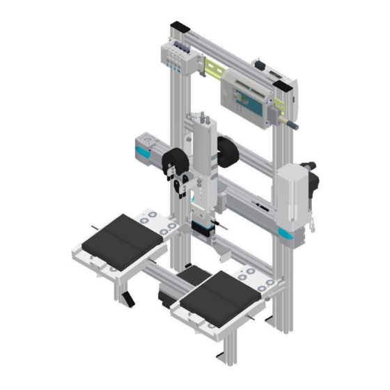
Keep away any dust from the station resulting from construction works (covering). 4.4 The application module output The application module output is designed for Using an electro-pneumatic, two-axis handling device, the good / bad parts must be dispensed on two ramps. © Festo Didactic Output... -
Page 25: Function
6. The gripper is opened to place the workpiece on the ramp 7. If the workpiece has slipped downwards (detection by the sensors), the X axis moves to the center position. Note: When you place the part, the Z-axis does not move. © Festo Didactic Output... -
Page 26: Electrical Connections
I/O terminal (2) on the module's electrical board. The example refers to the connection to a basic module linear, it is possible that the terminal names of the I/O terminal differ when connected to another module. Electrical connection by I/O example © Festo Didactic Output... -
Page 27: I/O Box Xd1
Open cylinder clamp unit XD1 / XK:O2 XD1:XS3 Open gripper XD1 / XK:O3 XD1:XS4 Controller enable XD1 / XK:O4 XD1:XS5 Traversing selection XD1 / XK:O5 XD1:XS6 XD1:XS7 Bit 1 XD1 / XK:O6 Start positioning XD1 / XK:O7 XD1:XS8 © Festo Didactic Output... -
Page 28: I/O Terminal Xd15
Controller enable XD15:XS5 XD15 / XK:O4 K5-KF12:5 / Q2.4 Traversing selection XD15:XS6 XD15 / XK:O5 K5-KF12:6 / Q2.5 Bit 1 XD15:XS7 XD15 / XK:O6 K5-KF12:7 / Q2.6 Start positioning XD15:XS1 XD15 / XK:O0 K5-KF12:1 / Q2.0 © Festo Didactic Output... -
Page 29: Start Up
5.2 Mechanical Setup All components, pipe connections and wirings are marked clearly in order to guarantee an unproblematic re- establishment of all connections. The graphics for the pneumatic and the electric connections are described exemplarily as follows. © Festo Didactic Output... -
Page 30: Connection Of Application Module
Put in slot nuts Then you install the application module. The slot nuts must be placed now under the mounting brackets so that the screws can be fixed. © Festo Didactic Output... - Page 31 Please make sure that the workpieces can be transferred correctly like here at the application module magazine. Once the position has been fixed, you only have to tighten the screws and to put the covers on the mounting brackets. © Festo Didactic Output...
-
Page 32: Pneumatic Port Of Application Module
the mechanic components regarding visible faults (cracks, loose connections etc.) the function of the Emergency Stop Please make sure that all damages discovered are removed before starting the station! © Festo Didactic Output... -
Page 33: Adjusting The Sensors
Start up 5.4 Adjusting the sensors 5.4.1 Through-beam sensor (Workpiece detection) Position Designation Sensor socket with sensor and light deflection/ 165360 (SOEZ-LLK-SE-2,0-M4) Sensor socket with sensor and light deflection/ 165360 (SOEZ-LLK-SE-2,0-M4) fibre-optic unit 165327 (SOEG-L-Q30-P-A-S-2L) © Festo Didactic Output... - Page 34 Please put a workpiece into the sensing range of the light barrier. The switching status display will disappear. You have to do this with all 3 light barriers. Please pay special attention to the corresponding function. Documents Data sheets / Operating instructions Fibre-optic unit SOEG_L (165327) and through-beam sensor SOEZ-LLK-SE-2,0-M4 (165360) © Festo Didactic Output...
-
Page 35: Proximity Switch (Z-Axis)
Z-axis lower position / 551373 (SMT-10M-PS-24V-E-25-L-OE) The proximity switches are used for checking the end position of the cylinder for the Z-axis. The proximity switches react to a permanent magnet on the piston of the cylinder. © Festo Didactic Output... - Page 36 5. Tighten the locking screw of the proximity switch with an Allen key SW1.3. 6. Please check the position of the proximity switch by repeated test runs of the cylinder. Documents Data sheets / operating instructions Proximity switch SMT-10M (551373) © Festo Didactic Output...
-
Page 37: Proximity Switch (Reference Sensor X-Axis)
Switching flag / 558046 (SF-EGC-1-50) Reference sensor X-axis / 551386 (SIES-8M-PS-24V-K-7,5-OE) The proximity switch is used to refer to the X axis. The proximity switch reacts to the switching flag on the driver of the axle. © Festo Didactic Output... - Page 38 5. Tighten the locking screw of the proximity switch with an Allen key SW1.3. 6. Please check the position of the proximity switch by repeated test runs of the axis. Documents Data sheets / operating instructions Proximity switch 551386 / SIES-8M-PS-24V-K-7,5-OE © Festo Didactic Output...
-
Page 39: Proximity Switch (Gripper)
Sensor gripper opened / 547859 (SMT-8G-PS-24V-E-2,5Q-OE) The proximity switches are used for checking the end position of the cylinder for the Z-axis. The proximity switches react to a permanent magnet on the piston of the cylinder. © Festo Didactic Output... - Page 40 5. Tighten the locking screw of the proximity switch with an Allen key SW1.3. 6. Please check the position of the proximity switch by repeated test runs of the gripper. Documents Data sheets / operating instructions Proximity switch 547859 / SMT-8G-PS-24V-E-2,5Q-OE © Festo Didactic Output...
-
Page 41: Adjusting The One-Way Flow Control Valves
One way flow control valves Position Designation One-way flow control valves GRLA for Z-axis cylinder One-way flow control valve GRLA for Z-axis cylinder One-way flow control valves GRLA for gripper One-way flow control valves GRLA for gripper © Festo Didactic Output... -
Page 42: Visual Inspection
the mechanic components regarding visible faults (cracks, loose connections etc.) the function of the Emergency-Stop settings Please make sure that all damages discovered are removed before starting the application module! © Festo Didactic Output... -
Page 43: Operation
If the application module is mounted on a CP Lab transport system or on a CP Factory basic module, the general operation is described in these manuals. All application-specific information is described in the application module manual. -
Page 44: Sequence Description Of The Application Module Output
Components 6.2 Sequence description of the application module output Adjusting sequence © Festo Didactic Output... - Page 45 Components Automatic Mode sequence step 1 © Festo Didactic Output...
- Page 46 Components Automatic Mode sequence step 2 © Festo Didactic Output...
- Page 47 Components Sequence decription with error © Festo Didactic Output...
-
Page 48: Setting The Application Module Output At Hmi
To set the application module, the application module must be set to setup mode. 1. On the Start screen, click Setup Change to the setup page (1) and select the application (2). Use the button axis control (3) to display the values of the axis. © Festo Didactic Output... - Page 49 GM_MB3: Indicator (lights up green when clamp is open) Clamp: Display Clamp Deposit place left occupied: Sensor VN_BG4 Display (lights up green when storage space is occupied) Deposit place right occupied: Sensor VN_BG5 Display (lights up green when storage space is occupied) © Festo Didactic Output...
- Page 50 Components 3. Select the axis controller; here all current values of the axis controller are displayed. © Festo Didactic Output...
-
Page 51: Transitions Of The Application Module
Components 6.4 Transitions of the application module The transitions are located in the Parameters submenu The transitions can be displayed or changed here. The transitions are used in the default mode, see also the following chapter. © Festo Didactic Output... -
Page 52: Parameter Of Application
Description Storage space [-] 1: Deposit position left (view direction CP Lab conveyor, CP Factory basic module) 2: Deposit position right (view direction: CP Lab conveyor, CP Factory basic module) Limitation: No limit of the value in the transition table... -
Page 53: Spare Part List
Spare part list 7 Spare part list Key 8027302 24V cable 381525 © Festo Didactic Output... -
Page 54: Service And Cleaning
Service and cleaning 8 Service and cleaning The components and systems from Festo Didactic are largely maintenance-free. At regular intervals you should have checked: the lenses of the optical sensors, fibre optics and reflectors the active surface of the proximity switch ... -
Page 55: Further Information And Updating
Service and cleaning 9 Further information and updating Further information and updates on the technical documentation of Festo Didactic components and systems can be found on the Internet at: www.ip.festo-didactic.com © Festo Didactic Output... -
Page 56: Disposal
Disposal 10 Disposal NOTICE Old electronic devices are recyclables and do not belong in the household waste. Disposal takes place via the municipal collection points. © Festo Didactic Output... - Page 57 Spare part list Festo Didactic SE Rechbergstraße 3 73770 Denkendorf Germany +49 711 3467-0 www.festo-didactic.com +49 711 34754-88500 did@festo.com © Festo Didactic Output...
Need help?
Do you have a question about the CP Factory and is the answer not in the manual?
Questions and answers