Festo CP Lab Manual
Conveyor
Hide thumbs
Also See for CP Lab:
- Manual (85 pages) ,
- Original operating instructions (90 pages) ,
- Manual (42 pages)
Table of Contents
Advertisement
Advertisement
Table of Contents

Related Manuals for Festo CP Lab


Summary of Contents for Festo CP Lab
- Page 1 8092739 Conveyor CP Lab Manual Festo Didactic 11/2019...
- Page 2 Schober, Weiss Layout: Frank Ebel File Name: CP-L-CONV-GB-A004.doc © Festo Didactic SE, Rechbergstraße 3, 73770 Denkendorf, Germany, 2019 +49 711 3467-0 www.festo-didactic.com +49 711 34754-88500 did@festo.com Reproduction, distribution and utilisation of this document, as well as the communication of its contents to others without explicit authorisation, is prohibited.
-
Page 3: Table Of Contents
2.12 Important Notes _____________________________________________________________________ 21 2.13 Environmental Requirements __________________________________________________________ 21 2.14 Intended use ________________________________________________________________________ 22 3 Introduction _____________________________________________________________________________ 23 3.1 General information CP Lab system ______________________________________________________ 23 3.1.1 Application modules _______________________________________________________________ 24 3.2 Resources ___________________________________________________________________________ 32 4 Design and Function ______________________________________________________________________ 35 4.1 Transport ____________________________________________________________________________ 35... - Page 4 5.5.1 Assembly of an CP application module ________________________________________________ 56 5.5.2 Connecting the CP application module electrically to the basic module CP Factory ____________ 59 5.5.3 Connecting the CP application module electrically to basic module CP Lab Conveyor__________ 60 5.5.4 Pneumatic port of application module ________________________________________________ 62 5.5.5 Electrical connection of application modules ___________________________________________ 62...
- Page 5 8.2 Extension with a passive corner ________________________________________________________ 105 8.3 Robotino docking extension ___________________________________________________________ 107 9 Spare part list ___________________________________________________________________________ 110 10 Service and cleaning ____________________________________________________________________ 111 11 Further information and updating _________________________________________________________ 112 12 Disposal ______________________________________________________________________________ 113 © Festo Didactic Conveyor...
-
Page 6: Legal Information
Crushing hazard. Never touch the system during operation. WARNING …indicates that death or severe personal injury may result if proper precautions are not taken. Strong optical radiation. Failure to comply may result in serious personal injury. © Festo Didactic Conveyor... - Page 7 If more than one degree of danger is present, the warning notice representing the highest degree of danger will be used. A notice warning of injury to persons with a safety alert symbol may also include a warning relating to property damage. © Festo Didactic Conveyor...
-
Page 8: Qualified Personnel
The information in the relevant documentation must be observed. 1.3 Trademarks All names identified by ® are registered trademarks of Festo. The remaining trademarks in this publication may be trademarks whose use by third parties for their own purposes could violate the rights of the owner. -
Page 9: General Requirements For Operating The Devices
Do not use devices with damage or defects. - Damaged equipment must be locked and removed from the laboratory or classroom. - Damaged connecting cables, compressed air hoses and hydraulic hoses are stopped. Security risks must be removed from the laboratory or classroom. © Festo Didactic Conveyor... -
Page 10: Fundamental Safety Instructions
For missing or incorrectly implemented protective conductor connection for devices with protection class I, high voltages can be present at open, exposed parts which, when touched, can result in death or severe injury. • Ground the device in compliance with the applicable regulations. © Festo Didactic Conveyor... - Page 11 In operation, devices can reach high temperatures, which can cause burns, if touched. • Take measures, when maintenance is required. • Allow the device to cool down before starting any work. • Use the appropriate personnel protection equipment, e.g. gloves. © Festo Didactic Conveyor...
-
Page 12: Warranty And Liability For Application Examples
2.3 Industrial Security Note Festo provides products and solutions with industrial security functions that support the secure operation of plants, systems, machines and networks. In order to protect plants, systems, machines and networks against cyber threats, it is necessary to implement – and continuously maintain – a holistic, state-of-the-art industrial security concept. -
Page 13: Further Safety Instructions
If not otherwise specified in the technical data, the device is not equipped with an integrated fuse. WARNING This is a Class A product. In a domestic environment, this product may cause radio interference in which case the user may be required to take adequate measures. © Festo Didactic Conveyor... -
Page 14: Pictograms
Laser beam Non-observance of this pictogram may result in personal injury. Strong optical radiance Non-observance of this pictogram may result in personal injury. © Festo Didactic Conveyor... - Page 15 Important This symbol emphasizes important information for correct machine handling. Failure to pay attention to this symbol may result in damages to the machine or to its surroundings. © Festo Didactic Conveyor...
-
Page 16: Safety Sockets
Protective grounding terminal (green-yellow) as PE+ contact The specified protection class and safe use will be achieved, if laboratory safety cables supplied by Festo Didactic are used. Notice The device might not include all the laboratory safety sockets shown above. Further safety sockets may be included in the training setup. - Page 17 When equipment is connected to an unsuitable power supply, exposed components may carry a hazardous voltage that might result in serious injury or death. Only use power supplies that provide SELV or PELV (see section legal information). © Festo Didactic Conveyor...
-
Page 18: Handling The System
Caution! When the air pressure supply is activated, cylinders may move in or out. Do not uncouple any tubes under air pressure supply. Exception: fault finding. In this case, keep on holding the end of the tube. Do not exceed the permitted operating pressure. See data sheets. © Festo Didactic Conveyor... -
Page 19: Maintenance - Servicing - Malfunction Removal
There is a risk of fire if power supply is not of the energy limited type (see section 2.1). 2.7.8 Safe Handling Safe handling of heavy equipment must be guaranteed! There is a risk of musculoskeletal harm if instructions are not followed. © Festo Didactic Conveyor... -
Page 20: Personnel
All persons who have been entrusted to work with the system undertake to complete the following steps before starting to work: read the chapter concerning safety and the warnings in this manual observe the basic regulations on occupational safety and accident prevention. © Festo Didactic Conveyor... -
Page 21: Warranty And Liability
Catastrophes as a result of foreign bodies and vis major. Festo Didactic herewith rules out any liability for damage or injury to trainees, the training company and/or other third parties which may occur during the use/operation of the system other than purely in a training situation, unless such damage has been caused intentionally or due to gross negligence by Festo Didactic. -
Page 22: Intended Use
• Only to be operated with the robot program supplied by us. Only the use listed in the operating instructions is considered intended use. Other uses, of whatever nature, are considered improper use and are solely at the responsibility of the operator. © Festo Didactic Conveyor... -
Page 23: Introduction
The CP Lab system is developed for all apprentices who want to move something. It doesn’t matter if the education is for electro- or metal profession, for mechatronics, technician- or engineer education. -
Page 24: Application Modules
CP application module ASRS for workpieces for loading / unloading workpieces Complexity high, 2 toothed belt axes CP application module Camera inspection With camera for checking object properties Complexity high, Festo Camerasystem with evaluation software © Festo Didactic Conveyor... - Page 25 Introduction CP application module dispensing to distribute balls in three different colors and diameters Complexity high, electropneumatic module CP application module drilling For drilling housing parts Complexity simple, electro pneumatic module © Festo Didactic Conveyor...
- Page 26 For heating workpieces for thermal processing Complexity medium to high, control engineering module with analog processing and PWM CP application module iDrilling For drilling housing parts Complexity simple, electro-pneumatic module with controller with web interface for cyber-physical system © Festo Didactic Conveyor...
- Page 27 In order to label workpieces with a label Complexity high, electro pneumatic module CP application module magazine For feeding housing parts. Different in the magazine rear cover and magazine front cover Complexity simple, electro pneumatic module © Festo Didactic Conveyor...
- Page 28 CP application module manual work For the manual processing of pallets and / or workpieces on a stopper Complexity simple, software module CP application module Measuring For quality assurance Complexity high, processing of analog input signals © Festo Didactic Conveyor...
- Page 29 Introduction CP application module Muscle press For pressing the housing parts Complexity simple, electro pneumatic module (pneumatic muscle) CP application module output For removing workpieces from the system Complexity medium, electro pneumatic module © Festo Didactic Conveyor...
- Page 30 Introduction CP application module Pick by light Hand workplace where workpieces are provided for assembly. Complexity, electrical module CP application module press For pressing the housing parts Complexity simple, electro pneumatic module © Festo Didactic Conveyor...
- Page 31 Introduction CP application module turn over For turning workpieces Complexity medium, electro pneumatic module © Festo Didactic Conveyor...
-
Page 32: Resources
The training equipment of the system consists of several resources. They are used depending on the process selection. The following resources are available: Pallet carrier These pallet carriers are available for transporting the pallets. Pallet These pallets are available for receiving always one workpiece. © Festo Didactic Conveyor... - Page 33 No. 109 No. 212 CP front cover black CP Frontcover black right fuse No. 110 No. 213 CP back cover black CP Frontcover black both fuses No. 111 No. 214 CP back cover grey No. 112 © Festo Didactic Conveyor...
- Page 34 No. 1211 CP Frontcover blue right fuse CP black with left fuse No. 413 No. 1212 CP Frontcover blue both fuses CP black with right fuse No. 414 No. 1213 CP black with both fuses No. 1214 © Festo Didactic Conveyor...
-
Page 35: Design And Function
Allen key size 4-6. It might happen that the connectors are loosened during the transport due to inevitable vibrations. Please pay special attention to any protruding components. Sensors or other small parts may easily be damaged during an improper transport. © Festo Didactic Conveyor... -
Page 36: Overview Of The System
4.2 Overview of the System CP Lab Conveyor, CP Factory Linear, CP Factory Shunt and CP Factory Bypass are called basic modules. If an application module, e.g. the CP Application Module press is attached to a basic module, it becomes a station. -
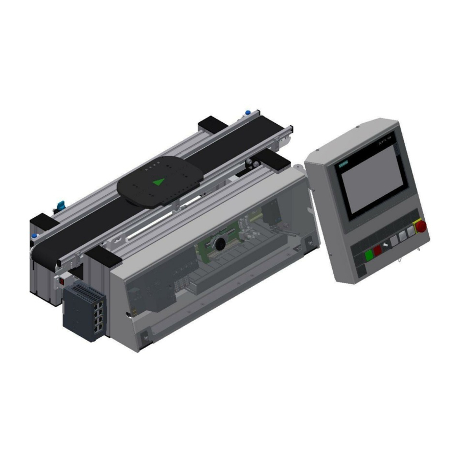
Page 37: The Cp Lab Conveyor
On the basic frame, there are coupling sensors for an easy communication with other directly connected CP Lab conveyors. At the start and at the end of the CP Lab conveyor, there are capacitive sensors which recognize the pallet on the CP Lab conveyor. ... - Page 38 Position Description Position Description Carrier Scalance Ethernet switch (optional) On-off valve Control panel / Touch panel (optional) Capacitive sensor start of conveyor Basic frame Conveyor Control cabinet for electrical components and controlling Coupling sensor previous station © Festo Didactic Conveyor...
-
Page 39: Stopper Unit
4.4 Stopper unit The stopper unit is located in the middle of the CP Lab conveyor. The carrier runs over the extended stopper unit. The screw (pos. 1 picture below) runs into the slot of the carrier. At the end of the slot the carrier is stopped. - Page 40 Inductive sensor 157211 / AEVUZ-16-5-P-A 150395 / SIEN-M8NB-PS-S-L Flow control supply air RFID read-write head M18 193967 / GR-QS-4 Siemens 6GT2821-1AC32 Flow control exhaust air Valve stopper with manual override 193967 / GR-QS-4 574351 / VUVG-L10-M52-MT-M5-1P3 © Festo Didactic Conveyor...
- Page 41 The CP Factory / Lab stop unit consists of 1 spring-return cylinder AEVUZ-16-5-P-A with 2 pneumatic connections 2 One-way flow control valves (exhaust air throttles) 1 monostable 5/2-way valve (VUVG-L10-M52-MT-M5-1P3) 1 brass element 1 spring © Festo Didactic Conveyor...
- Page 42 If no carrier is located above the stopper, the brass element also returns to its basic position. The upward movement of the piston rod relaxes the spring between the brass element and the cylindrical body during the movement. This also pushes the brass element upwards. © Festo Didactic Conveyor...
- Page 43 In the case of small sizes of the single-acting cylinder with exhaust air throttling, no sufficiently large compressed air cushion can be built up in the chamber so that the mechanism of the exhaust air throttling has a positive effect © Festo Didactic Conveyor...
-
Page 44: Drive Vesions
Whether DC motor, AC motor or servo motor - the conveyor belt can be combined with all motors in just a few steps. Professional couplings or toothed belt transmissions convey maximum industrial practice with optimum didactic modularity. 4.5.1 Gear motor 36 V DC © Festo Didactic Conveyor... -
Page 45: Three-Phase Asynchronous Motor With Gearbox And Self-Ventilation 230 V Ac
Design and function 4.5.2 Three-phase asynchronous motor with gearbox and self-ventilation 230 V AC 4.5.3 Asynchronous motor with gearbox and self-ventilation 400 V AC © Festo Didactic Conveyor... -
Page 46: Signal Generator
Light barrier channel B (BG7) / signal or coupling sensor is selectable with switch on the circuit board (left turning signal, right coupling sensor) Light barrier channel A (BG8) / signal or coupling sensor is selectable with switch on the circuit board (left turning signal, right coupling sensor) © Festo Didactic Conveyor... -
Page 47: Electrical Connections
BG7. The output units can be connected alternatively to the coupling sensors. (left turning signal, right coupling sensor) The iPort is connected to the I/O link master of the ET200 SP. Instead of the controller, it is possible to install a I/O Terminal. © Festo Didactic Conveyor... - Page 48 4 I/O signals on this plug. The cable is connected to XZ1 /X12. The external power supply is connected with lab cables at the XZ1. With the SYSlink plug, applications are connected to the controller. © Festo Didactic Conveyor...
- Page 49 Electirc connection application module If an application module is connected to the CP Lab conveyor, the cable that is hardwired to X11 is plugged into the SYS-Link connector of the I / O terminal. If the application module has an analogue interface, the analogue terminal is plugged into the rear XZ2 board at interface X5.
-
Page 50: Activation Motors
Design and function 4.8 Activation motors 4.8.1 Motor version 36V © Festo Didactic Conveyor... -
Page 51: Motor Version 230V
Design and function 4.8.2 Motor version 230V Configured in triangle. Motor MA1 – Clamps G120 CU240-2PN / QA1- Clamps X1:1 X1:2 X1:3 X1:PE © Festo Didactic Conveyor... -
Page 52: Motor Version 400V
Design and function 4.8.3 Motor version 400V Motor MA1 – Clamps G120 CU240-2PN / QA1- Clamps U1 / W2 X1:1 V1 / U2 X1:2 W1 / V2 X1:3 PE / PE X1:PE © Festo Didactic Conveyor... -
Page 53: Commissioning
a CP Application Module a basic module CP Factory or a basic module CP Lab Conveyor for the installation of the CP Application Module a SysLink cable for the connection between the I/O terminal of the CP Application Module and the basic module CP Factory ... -
Page 54: Visual Inspection
The technical condition – mechanically and electrically – of the CP Application Module is perfect. The CP Application Module is used in accordance with the regulations. The operating instructions have been read and understood. All safety devices are available and active. © Festo Didactic Conveyor... -
Page 55: Connecting A Cp Lab
5.4.1 Pneumatic Commissioning The mechanic mounting has to be completed and finished. At first, the CP Lab conveyor has to be connected to the pneumatic system of the room. The required service unit has to be provided by the customer and should be in the immediate vicinity of it. -
Page 56: Assembly
The following description for the attachment to a basic module CP Lab Conveyor is an example for all basic modules and all application modules. Positioning slot nuts in the cross profiles of the basic module CP Lab Conveyor Mounting the CP application module is very easy: ... - Page 57 Attaching the application module to the basic module CP Lab Conveyor Put the CP application module on the basic module CP Lab Conveyor. Position the slot nuts (2) underneath the mounting brackets (1) of the CP application module so that the internal threads of the slot nuts are visible underneath the elongated holes of the mounting brackets.
- Page 58 Use raised head screws M5x8, in order to connect the mounting brackets (1) of the CP application module Measuring, at first loosely, with the cross profiles (2) of the basic module CP Lab Conveyor. After setting all raised head screws, you can still move the CP application module to the position required.
-
Page 59: Connecting The Cp Application Module Electrically To The Basic Module Cp Factory
CP application module: analogue terminal (+BG-XD2A) connecting cable with 15-pin D-Sub-plugs CP application module: I/O terminal (+BG-XD1) connecting cable with SysLink-plugs (SysLink-cable) electric board basic module CP Factory: I/O terminal (+K1-XD15) electric board basic module CP Factory: analogue terminal (+K1-XD16A) © Festo Didactic Conveyor... -
Page 60: Connecting The Cp Application Module Electrically To Basic Module Cp Lab Conveyor
Connect the I/O terminal (2) of the CP application module with the control (3) of the basic module CP Lab Conveyor. Therefore use the connecting cable with SysLink plugs (5) which has already been attached to the control and is led out on the back side of the basic module CP Lab Conveyor. Electrical connections... - Page 61 Connect the analogue terminal (1) of the CP application module with the D-Sub-interface for analogue signals (6) on the rear board of the basic module CP Lab Conveyor. Therefore use the provided connecting cable (4) with standard D-Sub plugs: 15-pin, two-rowed.
-
Page 62: Pneumatic Port Of Application Module
the mechanic components regarding visible faults (cracks, loose connections etc.) the function of the Emergency Stop Please make sure that all damages discovered are removed before starting the station! © Festo Didactic Conveyor... -
Page 63: Electrical Commissioning
Design and function 5.6.1 Electrical Commissioning Now the CP Lab conveyor has to be supplied with electric power (24V). The external power supply has to be connected as follows: 0V to XZ2 clamp 1 24V to XZ2 clamp 2 PE to XZ2 clamp 4 The appliances are connected to the other corresponding clamps. -
Page 64: Modus Switch
Design and function 5.6.2 Modus switch Independent if the Festo Didactic IO-Link-DA-Interface is used as IO-Link-Device or an field bus node, the wiring of the I-Port-interface hast to be changed. This is done by the circuit board: Switch position: Lower position 1=CTEU: A field bus node can be set on the Festo Didactic IO-Link-DA-Interface. -
Page 65: Emergency Stop System
24VB as well as all other objects at clamp XZ1 supplied by 24VNA. The second NC contact of the Emergency Stop mushroom actuator is used as a signal contact for the SPS and is located on inlet 1.5. © Festo Didactic Conveyor... - Page 66 Description Interface Voltage Name SysLink cable SysLink plug 24VB WG21 / WHPK XZ1/X11: VB WG21 / WHBU XZ1/X11: 0 XZ1/X11: 0V 24VA WG21 / BK XZ1/X11: VA WG21 / PKBN XZ1/X11: 0V WG21 / PUR XZ1/X11: 0V © Festo Didactic Conveyor...
- Page 67 X15:3 XG1:11 / O2 XJ1:3 APP_DO2 X15:4 XG1:12 / O3 XJ1:4 APP_DO3 X15:5 XG1:13 / O4 XJ1:5 APP_DO4 X15:6 XG1:14 / O5 XJ1:6 APP_DO5 X15:7 XG1:15 / O6 XJ1:7 APP_DO6 X15:8 XG1:16 / O7 XJ1:8 APP_DO7 © Festo Didactic Conveyor...
-
Page 68: Commissioning
5.7 Commissioning For the CP Lab conveyor, an initial start-up has been made ex works. Please follow the following instructions in order to be able to work with CP Lab conveyor as well as with a possibly present application: 1. CP-L-CONV with 36 V DC motor: Connect the power supply 230 V AC for the power supply unit and connect the 24 V supply cable of the module. -
Page 69: Operation
6 Operation The operation is explained with the help of an example. There might be deviations with other applications. 6.1 Menu structure of the CP Lab screen Position Description Menu designation (main menu or submenu) OR in case of an active error or an error message, this field also serves as a... -
Page 70: Menu Prompting
Operation 6.1.1 Menu prompting Home – Operation Mode Home - Overview © Festo Didactic Conveyor... - Page 71 Operation Home – User Mode Home – I/O Test © Festo Didactic Conveyor...
- Page 72 Operation Setup - Application Setup - belt © Festo Didactic Conveyor...
- Page 73 Operation Setup - Stopper © Festo Didactic Conveyor...
- Page 74 Operation Parameter - Application © Festo Didactic Conveyor...
- Page 75 Operation Parameter - Transitions Parameter - Conveyor © Festo Didactic Conveyor...
- Page 76 Operation System - Settings © Festo Didactic Conveyor...
-
Page 77: Operation
A flashing button invites the user to carry out an action. A button with a statically blue background indicates that the function described in the button text is active. Position Description Flashing button demands adjusting (release for adjusting mode has been given) – press button – adjusting mode is made active © Festo Didactic Conveyor... - Page 78 Automatic mode is displayed => press button – Automatic mode is made active Position Description Flashing button indicates that automatic mode is active Automatic mode can be stopped at the end of the cycle of the active process © Festo Didactic Conveyor...
-
Page 79: Message Line And Window
Error/warning is active – if you click on the message line, the message window will be called up Position Description The error/warning is displayed in the message window and can be acknowledged with this button. The acknowledgement is effected as a single acknowledgement. © Festo Didactic Conveyor... -
Page 80: Display Of Objects
6.2.2 Display of objects It generally applies: Inputs: green when active Outputs: orange when active Buttons/User interactive fields: grey backgrounds with blue text change to blue backgrounds with black text as soon as they are active. © Festo Didactic Conveyor... -
Page 81: Operator Assistance And Simulate Application On Free Ap
Thus every free AP provides the following functions in default mode as well as in MES mode: 1. Generic sequence simulation 2. Operator assictance The application function is added with a fitted application module 1. Process simulation of the application 2. Operator assictance 3. Application Function © Festo Didactic Conveyor... -
Page 82: Generic Sequence Simulation
2. The processing time in this case is 10 sec. This can be set in the parameters. The current time is indicated by the bar in progress. At the end of the simulation, the return value is transferred to MES. 3. The carrier is released from the application position. © Festo Didactic Conveyor... -
Page 83: Operator Assistance With Display Of Pictures
No action Front cover Check Back cover Extract Printed circuit board Assemble Front fuse (in direction of transport) Insert Rear fuse (in direction of transport) Apply Both fuses Rework Workpiece Reserve_7 Reserve_8 Reserve_8 Reserve_9 Reserve_9 Reserve_10 Reserve_10 © Festo Didactic Conveyor... - Page 84 3. In this case, element 2 and action 4 are specified in the transitions. The worker must insert a backcover. 4. If the worker has completed the task, he must press the Confirm button to complete the task. The data is transmitted to MES 5. The carrier is released from the application position. © Festo Didactic Conveyor...
-
Page 85: Operator Assistance With Call Of Htm-Page
4. If the worker has completed the task, he must press the Confirm button to complete the task. The data is transmitted to MES 5. The carrier is released from the working position. © Festo Didactic Conveyor... -
Page 86: Hmi Extension With G120 Frequency Converter
3. The outputs can be switched in this field (control word 1) (explanation below) 4. The override can be set in this field (explanation below) 5. The inputs / signals are displayed in this field (status word 1) (explanation below) © Festo Didactic Conveyor... - Page 87 Guidance by PLC - Control via interface, process data valid Direction reversal - motor will run counterclockwise in response to a positive setpoint. MOP higher - set the motor potentiometer higher MOP lower - Lower the motor potentiometer © Festo Didactic Conveyor...
- Page 88 Setpoint value - entry of the setpoint value by clicking in the field - an input mask appears and the desired setpoint can be entered. Only changeable in setup mode [rpm] Display of override - Change between 50/100 depending on the area code in the conveyor belt setup Actual value - display of the current override © Festo Didactic Conveyor...
- Page 89 Control requested - The automation system is requested to take over control. N comparison value reached I, M, or P-limit not reached Holding brake open - signal can be used to control a holding brake No motor overtemperature Motor rotates forwards No thermical oveload © Festo Didactic Conveyor...
-
Page 90: Components
Q1 indicator light white / light PF3 PF3 / X2: 6 / Q2 Q2 indicator light white / light PF4 PF4 / X2: 8 / Q3 Emergency Stop / button SF5 – at M12 panel plug © Festo Didactic Conveyor... -
Page 91: Front Pcb Xz1
-XZ1-X18 = incremental encoder BNC-Connector 1 -XZ1-X19 = incremental encoder BNC-Connector 2 -XZ1-X11 = terminals PCB front side -XZ1-X20 = connection to opposite PCB -XZ1-X1 = connection to opposite PCB -XZ1-X21 = Powersupply HMI -XZ1-X22 = external Emergency-Stop Connector © Festo Didactic Conveyor... -
Page 92: Back Pcb Xz2
-XZ2-X4 = power supply -XZ2-X2 = connection 1 to DA-Interface -XZ2-X3 = connection 2 to DA-Interface -XZ2-X5 = analog signals for application -XZ2-X6 = terminals PCB rear side -XZ2-X7 = connection to external Motorcontroller -XZ2-X8 = 24V application modules © Festo Didactic Conveyor... - Page 93 KF21:I18.4 / XZ3:B1 X3:1 X6:5 Coupling receiver left KF21:I18.5 / XZ3:B3 X3:3 X6:6 Stopper opened KF21:I18.7 / XZ3:B7 X3:7 X6:8 Coupling sender left KF21:Q18.4 / XZ3:B2 X3:2 X6:23 Coupling sender right KF21:I18.5 / XZ3:B4 X3:3 X6:24 © Festo Didactic Conveyor...
-
Page 94: Sys Link Cable - Interface
Output AX.3 Input EX.3 Output AX.4 Input EX.4 Output AX.5 Input EX.5 Output AX.6 Input EX.6 Output AX.7 Input EX.7 Power supply Power supply Power supply Power supply Power supply Power supply Power supply Power supply © Festo Didactic Conveyor... -
Page 95: Rfid Read/Write System
TW-R16-B128 RFID data storage medium Clamp read-write head Cable I/O Link TF1:1 / 24 V XTF1:1 / BN XG1/X12:1 - L+ TF1:3 / 0V XTF1:3 / BU XG1/X12:3 - L- TF1:4 / Data XTF1:4 / BK XG1/X12:2 - C/Q © Festo Didactic Conveyor... -
Page 96: Io-Link Da-Interface (Digital-Analogue Interface)
Clamp 3 – OVB / cable has a blue stranded wire Clamp 4 – Data / cable has a black stranded wire Clamp 5 – OVA / cable has a grey stranded wire Data channel A Data channel B © Festo Didactic Conveyor... -
Page 97: Scalance Ethernet Switch
Components 7.2 Scalance Ethernet Switch Siemens Scalance Ethernet switch The SCALANCE X208 has eight RJ-45 jacks for the connection of end devices or other network segments. © Festo Didactic Conveyor... -
Page 98: Control Systems
Components 7.2.1 Control systems The control unit regulates all processes as well as the communication in the CP Lab conveyor. Different control systems can be used. It is possible that a I/O Terminal is installed instead of an controller. ET200SP with CPU1512... - Page 99 DI / 8x 24VDC / K1-KF2 / 6ES7131-6BF00-0CA0 DI / 8x 24VDC / K1-KF3 / 6ES7131-6BF00-0CA0 DO / 8x 24VDC 0,5A / K1-KF4 / 6ES7132-6BF00-0CA0 DO / 8x 24VDC 0,5A / K1-KF5 / 6ES7132-6BF00-0CA0 CM / 4x IO-Link ST / K1-KF6 / 6ES7137-6BD00-0BA0 © Festo Didactic Conveyor...
-
Page 100: Signal Converter
The signal converter is a fibre optic unit with a teachable switching point. Signal converter 552796 / SOE4-FO-L-HF2-1P-M8 WARNING Not to be used as a safety component! Electric voltage! Before you work on the electricity, you have to switch off the voltage. © Festo Didactic Conveyor... - Page 101 => Sensor has its factory setting again Pilot line (ET) / Process of external Teach-in •3 s at +U / determine teach point 1 •open •3 s at +U / determine teach point 2 •open setting saved, end of external Teach © Festo Didactic Conveyor...
-
Page 102: Solenoid Valve
When you press it (non-locking), the cylinder drives the stopper unit down as long as you press it. When you press the manual override and turn it (locking), the cylinder drives down with long-lasting effect. Solenoid valve 574351 / VUVG-L10-M52-MT-M5-1P3 © Festo Didactic Conveyor... -
Page 103: Extensions
8.1 Extension with an active corner In order to make a circulation of several CP Lab conveyors, it is possible to assemble the CP Lab conveyors in the rectangle and to connect the conveyors with active corners. A motor drives the corner and the carrier is transported to the following CP Lab conveyor. - Page 104 Components Position Description Outside guard railing Turning table Inside guard railing Motor Coupling sensor transmission Coupling sensor transmission Screw Motor connection (see Circuit diagram p.13) © Festo Didactic Conveyor...
-
Page 105: Extension With A Passive Corner
8.2 Extension with a passive corner In order to achieve a circulation from several CP Lab conveyors, it is possible to assemble the CP Lab conveyor in the rectangle and to connect the conveyors with passive corners. The corners are equipped with balls which enable the carrier to be transported without drive to a further band mounted at a right angle. - Page 106 Components Position Description Ball caster Passive guard railing Coupling sensor transmission Coupling sensor transmission © Festo Didactic Conveyor...
-
Page 107: Robotino Docking Extension
Components 8.3 Robotino docking extension To dock a robotino to a CP Lab conveyor, a small profile construction is necessary. The necessary sensors are already available on the conveyor. Although they are not disassemled, the inputs of the coupling sensors are now used for the coupling of the robotinos. - Page 108 Components At positions 1 and 2 the deactivated sensors can be seen, they remain at the conveyor but are no longer connected. © Festo Didactic Conveyor...
- Page 109 If the docking extension is used for the robotino, the two toggle switches S1 and S2 must be changed over. Left position - encoder is used / docking extension deactivated Right position - Encoder is not used / docking extension activated © Festo Didactic Conveyor...
-
Page 110: Spare Part List
Spare part list 9 Spare part list Key 8027302 24V cable 381525 © Festo Didactic Conveyor... -
Page 111: Service And Cleaning
Service and cleaning 10 Service and cleaning The components and systems from Festo Didactic are largely maintenance-free. At regular intervals you should have checked: the lenses of the optical sensors, fibre optics and reflectors the active surface of the proximity switch ... -
Page 112: Further Information And Updating
Further information and updating 11 Further information and updating Further information and updates on the technical documentation of Festo Didactic components and systems can be found on the Internet at: www.ip.festo-didactic.com © Festo Didactic Conveyor... -
Page 113: Disposal
Disposal 12 Disposal NOTICE Old electronic devices are recyclables and do not belong in the household waste. Disposal takes place via the municipal collection points. © Festo Didactic Conveyor... - Page 114 Disposal Festo Didactic SE Rechbergstraße 3 73770 Denkendorf Germany +49 711 3467-0 www.festo-didactic.com +49 711 34754-88500 did@festo.com...
Need help?
Do you have a question about the CP Lab and is the answer not in the manual?
Questions and answers