Festo CP Lab Manual
Hide thumbs
Also See for CP Lab:
- Manual (114 pages) ,
- Original operating instructions (90 pages) ,
- Manual (39 pages)
Table of Contents
Advertisement
Advertisement
Table of Contents

Related Manuals for Festo CP Lab


Summary of Contents for Festo CP Lab
- Page 1 ® CPLab Manual CP Lab conveyor Festo Didactic CP Lab 03/2017...
- Page 2 The training company and/or the training staff must ensure that the trainees observe the safety precautions. Festo Didactic accepts no liability for injury or harm to trainees, the training company and/or any third parties occurring when the installation is used for any purpose apart from training, except Festo Didactic has caused such injury or harm intentionally or by grossly negligence.
-
Page 3: Table Of Contents
1.7 Obligations of the trainees ____________________________________________________________ 9 2 Introduction ___________________________________________________________________________ 10 2.1 Warranty and liability ________________________________________________________________ 10 2.2 Important notes ____________________________________________________________________ 10 2.3 General information CP Lab system ____________________________________________________ 11 2.3.1 Application modules _____________________________________________________________ 12 2.4 Resources _________________________________________________________________________ 19 3 Design and function ____________________________________________________________________ 21 3.1 Transport _________________________________________________________________________ 21... - Page 4 4.2.1 Find and select the PLC ___________________________________________________________ 47 4.2.2 Download the project ____________________________________________________________ 51 4.2.3 The PLC can be reset _____________________________________________________________ 55 4.3 Menu structure of the CP Lab screen ___________________________________________________ 57 4.3.1 Menu prompting ________________________________________________________________ 58 4.4 Operation _________________________________________________________________________ 65 4.4.1 Message line and window ________________________________________________________ 67...
-
Page 5: General Safety Instructions
Protective earth must always be connected first (before voltage), and must always be disconnected last (after voltage). If not otherwise specified in the technical data, the device is not equipped with an integrated fuse. © Festo Didactic CP Lab conveyor... -
Page 6: Pictograms
Failure to pay attention to this symbol may result in damages to the machine or to its surroundings. Information This symbol indicates operational tips and especially useful directions. This symbol assists you to make optimal use of all of your machine’s functions. © Festo Didactic CP Lab conveyor... -
Page 7: Safety Sockets
(green-yellow) signal input/output (black) The specified protection class and safe use can only be assured if laboratory safety cables supplied by Festo Didactic are used. Damaged laboratory safety cables must be immediately barred from further use and removed from the test area. -
Page 8: Handling The System
Secure the compressed air and electricity supplies to prevent unintentional start-up. During inspections, maintenance and repair work, the machine must be de-energized, de-pressurized and secured against unexpected restart. All screw connections released during maintenance, inspection or repair work must be checked to ensure correct re-tightening. © Festo Didactic CP Lab conveyor... -
Page 9: Organizational Measures
All persons who have been entrusted to work with the system undertake to complete the following steps before beginning work: Read the chapter concerning safety and the warnings in this manual Observe the basic regulations on occupational safety and accident prevention. © Festo Didactic CP Lab conveyor... -
Page 10: Introduction
Catastrophes as a result of foreign bodies and vis major. Festo Didactic herewith rules out any liability for damage or injury to trainees, the training company and/or other third parties which may occur during the use/operation of the system other than purely in a training situation, unless such damage has been caused intentionally or due to gross negligence by Festo Didactic. -
Page 11: General Information Cp Lab System
Facts are partly described with the help of graphics or images sub serving an easier understanding. The CP Lab system is developed for all apprentices who want to move something. It doesn’t matter if the education is for electro- or metal profession, for mechatronics, technician- or engineer education. -
Page 12: Application Modules
Introduction 2.3.1 Application modules CP application module output For removing workpieces from the system Complexity medium, electro pneumatic module CP application module drilling For drilling housing parts Complexity simple, electro pneumatic module © Festo Didactic CP Lab conveyor... - Page 13 For drilling housing parts Complexity simple, electro-pneumatic module with controller with web interface for cyber-physical system CP application module labeling In order to label workpieces with a label Complexity high, electro pneumatic module © Festo Didactic CP Lab conveyor...
- Page 14 For the manual processing of pallets and / or workpieces on a stopper Complexity simple, software module CP application module Camera inspection With camera for checking object properties Complexity high, Festo Camerasystem with evaluation software © Festo Didactic CP Lab conveyor...
- Page 15 For feeding housing parts. Different in the magazine rear cover and magazine front cover Complexity simple, electro pneumatic module CP application module Measuring For quality assurance Complexity high, processing of analog input signals © Festo Didactic CP Lab conveyor...
- Page 16 CP application module Muscle press For pressing the housing parts Complexity simple, electro pneumatic module (pneumatic muscle) CP application module Pick by light Hand workplace where workpieces are provided for assembly. Complexity, electrical module © Festo Didactic CP Lab conveyor...
- Page 17 For pressing the housing parts Complexity simple, electro pneumatic module CP application module heat tunnel For heating workpieces for thermal processing Complexity medium to high, control engineering module with analog processing and PWM © Festo Didactic CP Lab conveyor...
- Page 18 Introduction CP application module turning For turning workpieces Complexity medium, electro pneumatic module © Festo Didactic CP Lab conveyor...
-
Page 19: Resources
The training equipment of this system consists of several resources to be used depending on the process selection. The following resources are available: Carrier These carriers are available for the transport of the pallets. Pallet These pallets are available for receiving one workpiece each. © Festo Didactic CP Lab conveyor... - Page 20 No. 212 No. 1212 CP fuse right CP Customer part with fuse right No. 213 No. 1213 CP both fuses CP Customer part with both fuses No. 214 No. 1214 CP customer part No. 1210 © Festo Didactic CP Lab conveyor...
-
Page 21: Design And Function
To ensure fault-free operation a load-bearing floor is required to avoid settling. Allow sufficient distance between the installation and the wall of the room. Any dust originating from construction work has to be kept off the installation (by covering). © Festo Didactic CP Lab conveyor... -
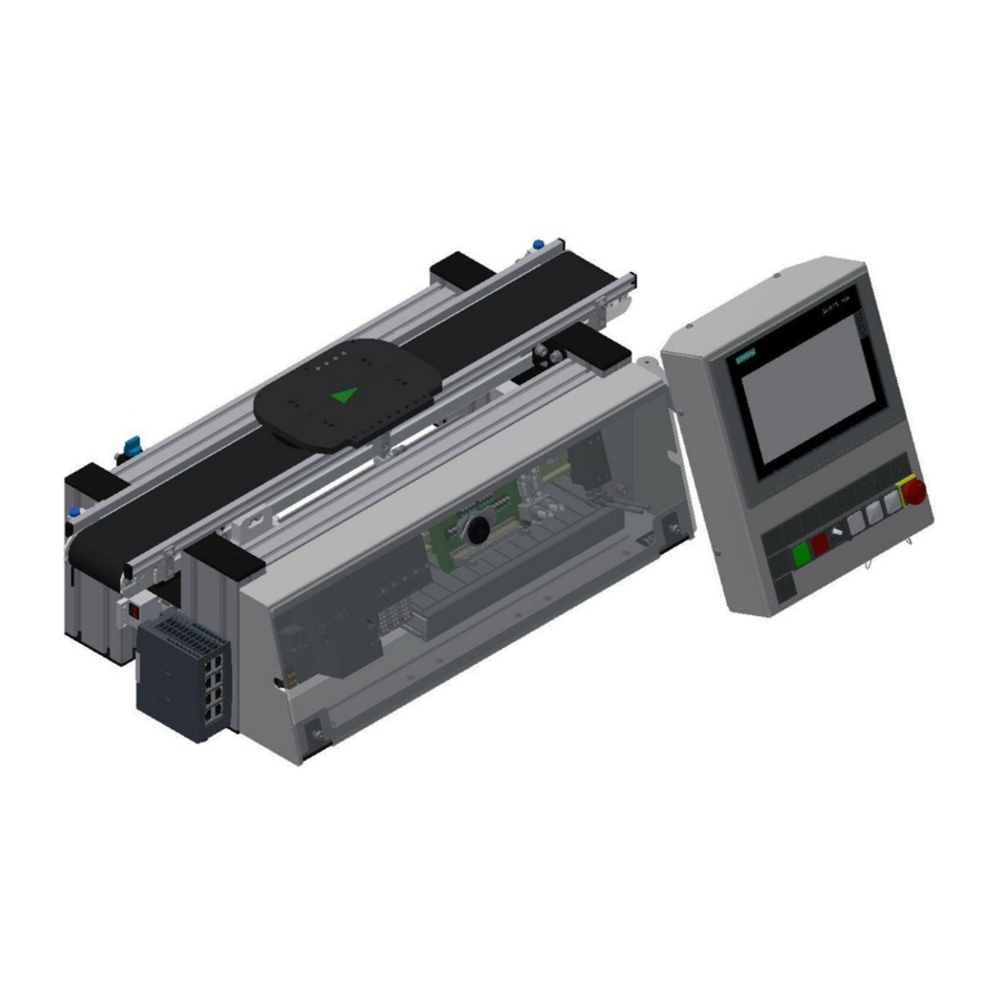
Page 22: The Cp Lab Conveyor
On the basic frame, there are coupling sensors for an easy communication with other directly connected CP Lab conveyors. At the start and at the end of the CP Lab conveyor, there are capacitive sensors which recognize the pallet on the CP Lab conveyor. ... - Page 23 Description Position Description Carrier Scalance Ethernet switch (optional) On-off valve Control panel / Touch panel Capacitive sensor start of conveyor Basic frame Conveyor Control cabinet for electrical components and controlling Coupling sensor previous station © Festo Didactic CP Lab conveyor...
-
Page 24: Stopper Unit
3.4 Stopper unit The stopper unit is located in the middle of the CP Lab conveyor. The carrier runs over the extended stopper unit. The screw (pos. 1 picture below) runs into the slot of the carrier. At the end of the slot the carrier is stopped. - Page 25 157211 / AEVUZ-16-5-P-A 150395 / SIEN-M8NB-PS-S-L Flow control supply air RFID read-write head M18 193967 / GR-QS-4 Siemens 6GT2821-1AC32 Flow control exhaust air Valve stopper with manual override 193967 / GR-QS-4 574351 / VUVG-L10-M52-MT-M5-1P3 © Festo Didactic CP Lab conveyor...
-
Page 26: Drive Variants
The professional couplings or toothed belt drives impart a maximum of industrial practice with the best possible didactic modularity. 24 V DC geared motor 3x230 V AC three phase asynchronous motor with gear unit and self-ventilation © Festo Didactic CP Lab conveyor... - Page 27 Design and function 400 V AC asynchronous motor with gear unit and self-ventilation © Festo Didactic CP Lab conveyor...
-
Page 28: Signal Generator
Light barrier channel B (BG7) / signal or coupling sensor is selectable with switch on the circuit board (left turning signal, right coupling sensor) Light barrier channel A (BG8) / signal or coupling sensor is selectable with switch on the circuit board (left turning signal, right coupling sensor) © Festo Didactic CP Lab conveyor... -
Page 29: Electrical Connections
BG7. The output units can be connected alternatively to the coupling sensors. (left turning signal, right coupling sensor) The iPort is connected to the I/O link master of the ET200 SP. Instead of the controller, it is possible to install a I/O Terminal. © Festo Didactic CP Lab conveyor... - Page 30 4 I/O signals on this plug. The cable is connected to XZ1 /X12. The external power supply is connected with lab cables at the XZ1. With the SYSlink plug, applications are connected to the controller. © Festo Didactic CP Lab conveyor...
-
Page 31: Connecting A Cp Lab
3.8.1 Pneumatic Commissioning The mechanic mounting has to be completed and finished. At first, the CP Lab conveyor has to be connected to the pneumatic system of the room. The required service unit has to be provided by the customer and should be in the immediate vicinity of it. -
Page 32: Electrical Commissioning
Design and function 3.8.2 Electrical Commissioning Now the CP Lab conveyor has to be supplied with electric power (24V). The external power supply has to be connected as follows: 0V to XZ2 clamp 1 24V to XZ2 clamp 2 PE to XZ2 clamp 4 The appliances are connected to the other corresponding clamps. -
Page 33: Modus Switch
Design and function 3.8.3 Modus switch Independent if the Festo Didactic IO-Link-DA-Interface is used as IO-Link-Device or an field bus node, the wiring of the I-Port-interface hast to be changed. This is done by the circuit board: Switch position: Lower position 1=CTEU: A field bus node can be set on the Festo Didactic IO-Link-DA-Interface. -
Page 34: Emergency Stop System
24VB as well as all other objects at clamp XZ1 supplied by 24VNA. The second NC contact of the Emergency Stop mushroom actuator is used as a signal contact for the SPS and is located on inlet 1.5. © Festo Didactic CP Lab conveyor... -
Page 35: Extended Functions With Applications
The assembly of an application is very easy. At first, 2 slot nuts M5 are put into the rear slot of the front cross profile of the CP Lab conveyor. There are also 2 slot nuts M5 to be put into the first slot of the rear cross profile. - Page 36 With raised head screws M5x8, the mounting brackets of the application are now connected with the cross profiles, but not yet tightened. When all screws are put into position, the application can still be moved to the position required. Once you have determined the position, all screws must be tightened. © Festo Didactic CP Lab conveyor...
-
Page 37: Pneumatic Connection Of Applications
(nominal size 4) into the QS plug of the valve terminal at the application. You have to put the second end of the tube on the on-off valve of the CP Lab conveyor. When you open the on-off valve, the application is supplied with compressed air. -
Page 38: Electrical Connection Of Applications
The applications are linked with the ET200SP through a SysLink interface. The SysLink cable is directly connected with the control system and comes out at the rear side of the CP Lab conveyor. The SysLink plug (XJ11) of the cable is plugged in at the application. Communication is made via I/O. - Page 39 Name SysLink cable SysLink plug 24VB WG21 / WHPK XZ1/X11: VB WG21 / WHBU XZ1/X11: 0 XZ1/X11: 0V 24VA WG21 / BK XZ1/X11: VA WG21 / PKBN XZ1/X11: 0V WG21 / PUR XZ1/X11: 0V © Festo Didactic CP Lab conveyor...
- Page 40 The application can also connect to an I/O terminal; via a SysLink interface they are directly connected. The SysLink plug (XJ11) of the cable is plugged in at the application. Communication is made via I/O. Electronic connection of the application © Festo Didactic CP Lab conveyor...
- Page 41 XG1:11 / O2 XJ1:3 APP_DO2 X15:4 XG1:12 / O3 XJ1:4 APP_DO3 X15:5 XG1:13 / O4 XJ1:5 APP_DO4 X15:6 XG1:14 / O5 XJ1:6 APP_DO5 X15:7 XG1:15 / O6 XJ1:7 APP_DO6 X15:8 XG1:16 / O7 XJ1:8 APP_DO7 © Festo Didactic CP Lab conveyor...
-
Page 42: Commissioning
3.10 Commissioning For the CP Lab conveyor, an initial start-up has been made ex works. Please follow the following instructions in order to be able to work with CP Lab conveyor as well as with a possibly present application: 1. Connect up the power supply 230 V AC for the power supply unit. -
Page 43: Operation
To load the device configuration or the PLC program to the PLC, it is necessary to mark the PLC at the navigation window. After that, the loading process can be started. 1. Mark the PLC and press the “Download to device” button at the toolbar. Load the projection into the PLC © Festo Didactic CP Lab conveyor... - Page 44 PLC. Choose the interface parameters and search the connected PLC with the “Start search” button. If the PLC is founded, press the “Load” button. Configure the PG/PC interface © Festo Didactic CP Lab conveyor...
- Page 45 4. If the compilation was successful, the actions of the TIA-Portal during the load process are announced. Please read each single action (for detailed information it is possible to open the action with the black arrows) and start the loading process. Confirm actions of loading process © Festo Didactic CP Lab conveyor...
- Page 46 Operation 5. After loading process, start the PLC. Therefor activate the „Start all“ box and press the „Finish“ button End of loading process 6. Check if the PLC is going into RUN mode. © Festo Didactic CP Lab conveyor...
-
Page 47: Software Festo
Step 1: Double click in this field Step 2. Device window Devices announcement In case Festo Field Device Tool is installed, the devices can be found with this tool Step 3: Type IP address here Insert IP Address and confirm with OK. - Page 48 Operation The view for the Device can be changed in Tools --> Options --> Device Editor 1. Scan network to find devices. © Festo Didactic CP Lab conveyor...
- Page 49 Operation 1. POUs window: the project elements here will be downloaded to all devices 2. In the Devices window, open the required device, right click and set as active application © Festo Didactic CP Lab conveyor...
- Page 50 Operation 3. Then the title becomes dark. 4. Finally, choose the right device and set as active path as well. 5. The title of the chosen device becomes dark. © Festo Didactic CP Lab conveyor...
-
Page 51: Download The Project
Operation 4.2.2 Download the project 1. Click on the build button (F11) 2. No errors © Festo Didactic CP Lab conveyor... - Page 52 4. This is downloading the project as well 5. After downloading the project, the PLC always in stop mode (7) 6. The green colour shows that the PLC is logged in (4) 7. Then click on Start (5) © Festo Didactic CP Lab conveyor...
- Page 53 Operation 8. PLC is running After logged in the PLC always in debug mode: the state is visible in runtime 9. Wrong hardware configuration shown with a red triangle © Festo Didactic CP Lab conveyor...
- Page 54 12. Create boot application: this project will be start at the next startup of the PLC (In case the boot application is not used, and a mistake appears in the code, by switching off and on the PLC, the original project will be restarted) © Festo Didactic CP Lab conveyor...
-
Page 55: The Plc Can Be Reset
1. Reset warm: just reinitializing the variables – mostly used 2. Reset cold: restart the PLC 3. Reset origin: clears the project from the PLC When the program needs to be edited, it has to logout from the PLC 1. Logout button © Festo Didactic CP Lab conveyor... - Page 56 3. Logging into debug mode without the changes 1. In case there are pointers or other special tools used in the project, after editing the code, a “Clean all” is recommended. This recalculates the memory allocation. © Festo Didactic CP Lab conveyor...
-
Page 57: Menu Structure Of The Cp Lab Screen
Operation 4.3 Menu structure of the CP Lab screen Position Description Menu designation (main menu or submenu) OR in case of an active error or an error message, this field also serves as a display Main menu Submenu in main menu... -
Page 58: Menu Prompting
Operation 4.3.1 Menu prompting Home – Operation Mode Home - Overview © Festo Didactic CP Lab conveyor... - Page 59 Operation Home – User Mode Home – I/O Test © Festo Didactic CP Lab conveyor...
- Page 60 Operation Setup - Application Setup - belt © Festo Didactic CP Lab conveyor...
- Page 61 Operation Setup - Stopper © Festo Didactic CP Lab conveyor...
- Page 62 Operation Parameter - Application © Festo Didactic CP Lab conveyor...
- Page 63 Operation Parameter - Transitions Parameter - Conveyor © Festo Didactic CP Lab conveyor...
- Page 64 Operation System - Settings © Festo Didactic CP Lab conveyor...
-
Page 65: Operation
A flashing button invites the user to carry out an action. A button with a statically blue background indicates that the function described in the button text is active. Position Description Flashing button demands adjusting (release for adjusting mode has been given) – press button – adjusting mode is made active © Festo Didactic CP Lab conveyor... - Page 66 => press button – Automatic mode is made active Position Description Flashing button indicates that automatic mode is active Automatic mode can be stopped at the end of the cycle of the active process © Festo Didactic CP Lab conveyor...
-
Page 67: Message Line And Window
Error/warning is active – if you click on the message line, the message window will be called up Position Description The error/warning is displayed in the message window and can be acknowledged with this button. The acknowledgement is effected as a single acknowledgement. © Festo Didactic CP Lab conveyor... -
Page 68: Display Of Objects
4.4.2 Display of objects It generally applies: Inputs: green when active Outputs: orange when active Buttons/User interactive fields: grey backgrounds with blue text change to blue backgrounds with black text as soon as they are active. © Festo Didactic CP Lab conveyor... -
Page 69: Components
Q1 indicator light white / light PF3 PF3 / X2: 6 / Q2 Q2 indicator light white / light PF4 PF4 / X2: 8 / Q3 Emergency Stop / button SF5 – at M12 panel plug © Festo Didactic CP Lab conveyor... -
Page 70: Front Pcb Xz1
Stop button / SF2 X12:3 Switch operation panel / SF3 X12:5 Reset button / SF4 X12:7 Start lamp / PF1 X12:2 Reset lampn / PF2 X12:4 Lamp Q1 / PF3 X12:6 Lamp Q2 / PF4 X12:8 © Festo Didactic CP Lab conveyor... -
Page 71: Back Pcb Xz2
Components 5.1.2 Back PCB XZ2 © Festo Didactic CP Lab conveyor... - Page 72 KF21:I18.4 / XZ3:B1 X3:1 X6:5 Coupling receiver left KF21:I18.5 / XZ3:B3 X3:3 X6:6 Stopper opened KF21:I18.7 / XZ3:B7 X3:7 X6:8 Coupling sender left KF21:Q18.4 / XZ3:B2 X3:2 X6:23 Coupling sender right KF21:I18.5 / XZ3:B4 X3:3 X6:24 © Festo Didactic CP Lab conveyor...
-
Page 73: Sys Link Cable - Interface
Input EX.3 Output AX.4 Input EX.4 Output AX.5 Input EX.5 Output AX.6 Input EX.6 Output AX.7 Input EX.7 Power supply Power supply Power supply Power supply Power supply Power supply Power supply Power supply © Festo Didactic CP Lab conveyor... -
Page 74: Rfid Read/Write System
Clamp read-write head Cable I/O Link TF1:1 / 24 V XTF1:1 / BN XG1/X12:1 - L+ TF1:3 / 0V XTF1:3 / BU XG1/X12:3 - L- TF1:4 / Data XTF1:4 / BK XG1/X12:2 - C/Q © Festo Didactic CP Lab conveyor... -
Page 75: Io-Link Da-Interface (Digital-Analogue Interface)
Clamp 3 – OVB / cable has a blue stranded wire Clamp 4 – Data / cable has a black stranded wire Clamp 5 – OVA / cable has a grey stranded wire Data channel A Data channel B © Festo Didactic CP Lab conveyor... -
Page 76: Control Systems
Components 5.1.6 Control systems The control unit regulates all processes as well as the communication in the CP Lab conveyor. Different control systems can be used. It is possible that a I/O Terminal is installed instead of an controller. ET200SP with CPU1512... - Page 77 DI / 8x 24VDC / K1-KF3 / 6ES7131-6BF00-0CA0 DO / 8x 24VDC 0,5A / K1-KF4 / 6ES7132-6BF00-0CA0 DO / 8x 24VDC 0,5A / K1-KF5 / 6ES7132-6BF00-0CA0 CM / 4x IO-Link ST / K1-KF6 / 6ES7137-6BD00-0BA0 © Festo Didactic CP Lab conveyor...
-
Page 78: Signal Converter
The signal converter is a fibre optic unit with a teachable switching point. Signal converter 552796 / SOE4-FO-L-HF2-1P-M8 WARNING Not to be used as a safety component! Electric voltage! Before you work on the electricity, you have to switch off the voltage. © Festo Didactic CP Lab conveyor... - Page 79 Pilot line (ET) / Process of external Teach-in •3 s at +U / determine teach point 1 •open •3 s at +U / determine teach point 2 •open setting saved, end of external Teach © Festo Didactic CP Lab conveyor...
-
Page 80: Solenoid Valve
When you press it (non-locking), the cylinder drives the stopper unit down as long as you press it. When you press the manual override and turn it (locking), the cylinder drives down with long-lasting effect. Solenoid valve 574351 / VUVG-L10-M52-MT-M5-1P3 © Festo Didactic CP Lab conveyor... -
Page 81: Extensions
6.1 Extension with an active corner In order to make a circulation of several CP Lab conveyors, it is possible to assemble the CP Lab conveyors in the rectangle and to connect the conveyors with active corners. A motor drives the corner and the carrier is transported to the following CP Lab conveyor. - Page 82 Components Position Description Outside guard railing Turning table Inside guard railing Motor Coupling sensor transmission Coupling sensor transmission Screw Motor connection (see Circuit diagram p.13) © Festo Didactic CP Lab conveyor...
-
Page 83: Extension With A Passive Corner
6.2 Extension with a passive corner In order to achieve a circulation from several CP Lab conveyors, it is possible to assemble the CP Lab conveyor in the rectangle and to connect the conveyors with passive corners. The corners are equipped with balls which enable the carrier to be transported without drive to a further band mounted at a right angle. - Page 84 Components Position Description Ball caster Passive guard railing Coupling sensor transmission Coupling sensor transmission © Festo Didactic CP Lab conveyor...
- Page 85 Components Festo Didactic SE Rechbergstraße 3 73770 Denkendorf Germany Internet: www.festo-didactic.com E-mail: did@de.festo.com © Festo Didactic CP Lab conveyor...
Need help?
Do you have a question about the CP Lab and is the answer not in the manual?
Questions and answers