Sign In
Upload
Manuals
Brands
Festo Manuals
Laboratory Equipment
CP Factory
Festo CP Factory Manuals
Manuals and User Guides for Festo CP Factory. We have
6
Festo CP Factory manuals available for free PDF download: Manual, Original Operating Instructions
Festo CP Factory Manual (126 pages)
Robot feeding for mill
Brand:
Festo
| Category:
Robotics
| Size: 9 MB
Table of Contents
Table of Contents
3
1 General Safety Instructions
6
Pictographs
7
Safety Terminal Sockets
8
Information for the Electrical Connection of the Systems
8
Handling the System
9
Dangers When Using the Machine
9
Safety Precautions in Normal Operation
9
Dangers Caused by Electrical Energy
9
Dangers Caused by Pneumatic Energy
9
Maintenance and Fault Clearance
9
Organizational Measures
9
Staff
10
Instructions Regarding the Staff
10
Training Operations
10
Beyond Training Operations
10
Commitment of the Operator
10
Commitment of the Trainees
10
2 Introduction
11
Warranty and Liability
11
Important Information
11
Resources
12
3 Design and Function
15
Transport
15
Set up
15
General Notes
15
Robot Feeding for Mill
16
General
16
Mechanical Structure
21
Supply of the Robot Feeding for Mill
25
Electrical Set up
27
Siemens PLC
29
Cabling Chart
31
Emergency Stop Structure
32
Emergency-Stop with Central Control
35
Commissioning
36
Pneumatic Commissioning
36
Electrical Commissioning
36
Commissioning
37
Pneumatic Commissioning
37
Electrical Commissioning
37
Adjusting the Sensors
38
Proximity Switch (Stopper Identsensor)
38
Proximity Switch (Stopper Cylinder)
40
Adjusting the One-Way Flow Control Valves
42
Visual Inspection
43
Starting up
43
4 Operation
44
General Notes on Operation
44
Handling Regulations
44
Operating Regulations
44
The Control Units of the Robot Feeding for Mill
45
Touch Panel
46
Sequence Description of Robot Feeding for Mill
47
Sequence Description of the Basic Module Bypass
49
CP Factory Loading Robot (Mill and Turn)
54
Switch on Robot
57
Operating Modes
58
Automatic Operation
58
Setup Mode
58
Operating the Hmi Touchpanel
58
Menu Architecture from Panel
59
Menu Navigation Robot Feeding for Mill
60
Display Operation Modus
62
Operation Mode Home
63
Operating Mode Setup
69
Operation Mode Parameters
76
Operation Mode System - Settings
80
Automatic Operation
81
Start Automatic
81
Stop Automatic
83
Writing on the RFID Tag Manually
84
Pallet Carriers
84
Boxes
86
Parameter CP Factory Feeding Robot and Mill
87
5 Components
88
Mitsubishi Robot RV-4FL
88
Drive Unit CR750-D
89
Teach Pendant R32TB
91
Teachpendant R56TB
92
Set up
93
Interface Drive Unit
96
Parameter
100
Main Tasks/Programmes
101
Return Message
101
Further Information to Robot
101
Robot Positions
102
Electrical Components
103
Quadrant Controller
103
Controller Siemens
106
Controller Festo CECC
107
Turck Interface
108
Scalance Ethernet Switch
109
RFID with Ethernet
112
RFID with Canbus
116
Mini Terminal
117
SYS Link Interface
121
Mechanic Components
122
Motor of Conveyor
122
The Stopper Unit
123
Transportation of the Basic Module
125
Advertisement
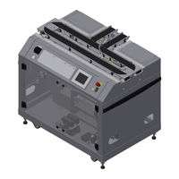
Festo CP Factory Manual (115 pages)
Basic module branch
Brand:
Festo
| Category:
Laboratory Equipment
| Size: 7 MB
Table of Contents
Table of Contents
3
1 General Safety Instructions
5
Pictographs
6
Safety Terminal Sockets
7
Information for the Electrical Connection of the Systems
7
Handling the System
8
Dangers When Using the Machine
8
Safety Precautions in Normal Operation
8
Dangers Caused by Electrical Energy
8
Dangers Caused by Pneumatic Energy
8
Maintenance and Fault Clearance
8
Organizational Measures
8
Staff
9
Instructions Regarding the Staff
9
Training Operations
9
Beyond Training Operations
9
Commitment of the Operator
9
Commitment of the Trainees
9
2 Introduction
10
Warranty and Liability
10
Important Information
10
Resources
11
3 Design and Function
13
Transport
13
Set up
13
General Notes
13
The Basic Module Branch
14
General Information
14
Mechanical Construction
16
Supply of the Branch Module
20
Electrical Assembly
22
Wiring Diagram
27
Emergency-Stop Structure
29
Emergency-Stop with Central Control
32
Connection of Application Module
34
Pneumatic Port of Application Module
36
Electrical Connection of Applications
37
Commissioning
38
Pneumatic Commissioning
38
Electrical Commissioning
38
Adjusting the Sensors
39
Proximity Switch (Stopper Identsensor)
39
Proximity Switch (Stopper Cylinder)
41
Proximity Switch (Branch Cylinder)
43
Adjusting the One-Way Flow Control Valves
45
Visual Inspection
47
Starting up
47
4 Operation
48
General Operating Instructions
48
Conduct Guidelines
48
Operating Guidelines
48
The Control Units of the Basic Module Branch
49
Touch Panel
50
Sequence Description of the Branch Module
53
Switching on the Station
57
Sequence Description Automatic
57
Process Description Cycle End
57
Operating Modes
58
Automatic Mode
58
Setting Operation
58
Operating the HMI Touch Panel
58
Menu Architecture from Operation Panel
59
Menu Navigation
60
Display Operation Modus
61
Operation Mode Home
62
Operating Mode Setup
68
Operation Mode Parameters
74
Operation Mode System - Settings
79
Operator Assistance and Simulate Application on Free AP
80
Generic Sequence Simulation
81
Operator Assistance with Display of Pictures
82
Operator Assistance with Call of Htm-Page
84
Automatic Operation
85
Start Automatic
85
Stop Automatic
87
Manually Describe the RFID Tag
88
5 Components
90
Electrical Components
90
Quadrant Controller
90
PLC Siemens
94
PLC Festo CECC
95
Turck Interface
96
Scalance Ethernet Switch
97
RFID with Ethernet
100
RFID with Canbus
104
Mini Terminal
105
SYS Link Interface
109
Mechanic Components
110
Motor of Conveyor
110
The Stopper Unit
111
The Branch
113
Transportation of the Basic Module Branch
114
Festo CP Factory Manual (97 pages)
MR Buffer and palletizing robot
Brand:
Festo
| Category:
Robotics
| Size: 5 MB
Table of Contents
Table of Contents
3
1 General Safety Instructions
6
Pictographs
7
Safety Terminal Sockets
8
Information for the Electrical Connection of the Systems
8
Handling the System
9
Dangers When Using the Machine
9
Safety Precautions in Normal Operation
9
Dangers Caused by Electrical Energy
9
Dangers Caused by Pneumatic Energy
9
Maintenance and Fault Clearance
9
Organizational Measures
9
Staff
10
Instructions Regarding the Staff
10
Training Operations
10
Beyond Training Operations
10
Commitment of the Operator
10
Commitment of the Trainees
10
2 Introduction
11
Warranty and Liability
11
Important Information
11
Resources
12
3 Design and Function
15
Transport
15
Set up
15
General Notes
15
MR Buffer Module with Palletizing Robot
16
General Information
16
Interface to Basic Module Bypass
17
Supply of the MR Buffer with Palletizing Robot
18
Electrical Installation
19
RFID Connections
23
Emergency-Stop Structure
24
Emergency-Stop with Central Control
28
Commissioning
29
Pneumatic Commissioning
29
Electrical Commissioning
29
Adjusting the Sensors
30
Fibre-Optic (Workpiece Detection)
30
Proximity Switch (Transfer Unit)
32
Proximity Switch (Indexing Units)
34
Proximity Switch (Transfer Unit)
36
Adjusting the One-Way Flow Control Valves
37
Visual Inspection
39
Commissioning
39
4 Operation
40
General Operating Instructions
40
Conduct Guidelines
40
Operating Guidelines
40
The Operation Panel of the Station
41
Touch Panel
42
Process Description
45
Process Description Box Stopper 1-4
46
Process Description Transfer Unit
48
Switching on the MR Buffer with Palletizing Robot
50
Switching on the Robot
50
Process Description Automatic Mode
50
Process Description Cycle End
50
Operating Modes
51
Automatic Mode
51
Setting Operation
51
Operating the HMI Touch Panel
51
Menu Structure of the Operating Panel
52
Menu Navigation in General
53
Operation Mode Home
55
Operation Mode Setup
59
Parameter
63
Operation Mode System
63
Starting the Automatic Mode
64
Terminating the Automatic Mode
66
Writing on the RFID Tag Manually
67
MR Buffer and Palletizing Robot Parameters
68
5 Components
69
Mitsubishi Robot RV-4FL
69
Drive Unit CR750-D
70
Teach Pendant R32TB
72
Teach Pendant R56TB
73
Set up
74
Drive Unit Interface
77
Parameter
80
Main Tasks/Programmes
81
Return Messages
81
More Information on the Robot
81
Robot Positions
82
Electrical Components
83
Quadrant Controller
83
Siemens Control
86
Scalance Ethernet Switch
87
Rfid
90
Terminal Block
91
SYS Link Interface
93
I/O Terminal
94
Advertisement
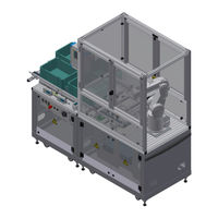
Festo CP Factory Original Operating Instructions (90 pages)
Brand:
Festo
| Category:
Industrial Equipment
| Size: 1 MB
Table of Contents
Table of Contents
3
Safety Instructions
5
Warning Notice System
5
Pictograms
6
General Prerequisites for Installing the Product
7
General Prerequisites for Operating the Devices
7
Intended Use
8
For Your Safety
9
Important Information
9
Qualified Persons
10
Obligations of the Operating Company
10
Obligations of the Trainees
10
Basic Safety Instructions
11
General Information
11
Mechanical Components
11
Electrical Components
12
Pneumatic Components
14
Guarantee and Liability for Application Examples
16
Cyber Security
16
Additional Safety Instructions
17
Guarantee and Liability
18
Transport
19
Name Plates
20
CE Declaration of Conformity
21
General Product Safety
24
Protective Devices
25
Emergency Stop
25
Additional Protective Devices
25
Technical Data
26
Design and Function
28
Transport
28
Overview of the System
30
The Application Module Labeling
31
Electrics
32
Pneumatic
35
Function
38
Sequence Description
38
Electrical Connections
40
Overview
40
I/O Box XD1
41
Commissioning
42
Workplace
42
Visual Inspection
43
Safety Regulations
43
Assembly
44
Assembly of an CP Application Module to Basic Module CP Lab Conveyor
45
Connecting the CP Application Module Electrically to Basic Module CP Lab Conveyor
48
Pneumatic Connection from Application Modules to Basic Module CP Lab Conveyor (Option - Not Available at All Application Modules)
50
Assembly of an CP Application Module to a CP Factory Basic Module
51
Connecting the CP Application Module Electrically to the CP Factory Basic Module
54
Pneumatic Connection from Application Modules to CP Factory Basic Module
55
Adjusting the Sensors
56
Through-Beam Sensor (Workpiece Detection)
56
Proximity Switch (Z and X-Axis Cylinder)
58
Vacuum Suction Nozzle
60
Adjusting the One-Way Flow Control Valves
62
Adjusting the Pressure Regulator
64
Operation
66
Setting the Application Module Labeling at HMI
66
Transitions of the Application Module
72
Process of the Application Module
73
Flow Chart
74
Parameter (LABEL)
80
Message Texts and Interactive Error Messages at the HMI
82
Message Texts
83
Message Texts of the Application Module Labeling
83
Interactive Error Messages
84
Default Operation
84
MES Operation
85
General
85
Application Module Labeling
85
Spare Part List
86
Electric Parts
86
Pneumatic Parts
86
Service and Cleaning
87
Further Information and Updating
88
Disposal
89
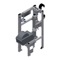
Festo CP Factory Manual (57 pages)
Application Modules
Brand:
Festo
| Category:
Control Unit
| Size: 2 MB
Table of Contents
Table of Contents
3
1 Legal Information
5
Warning Notice System
5
Qualified Personnel
7
Trademarks
7
Disclaimer of Liability
7
Preface
7
General Requirements for Operating the Devices
8
2 Fundamental Safety Instructions
9
General Safety Instructions
9
Warranty and Liability for Application Examples
11
Industrial Security
11
Further Safety Instructions
12
Pictograms
13
Safety Sockets
15
Handling the System
17
Dangers in Handling the Machine
17
Safety Precautions in Standard Operation
17
Dangers Due to Electric Current
17
Dangers Due to Pneumatic Energy
17
Maintenance - Servicing - Malfunction Removal
18
Organizational Measures
18
Energy Limiting
18
Safe Handling
18
Personnel
19
Notes on Personnel
19
Training Operations
19
Outside Training Operations
19
Obligations of the Operating Company
19
Obligations of the Trainees
19
Warranty and Liability
20
Important Notes
20
Environmental Requirements
20
3 Technical Data
21
4 Design and Function
22
Transport
22
Overview of the System
23
Set-Up
24
General Notes
24
The Application Module Output
24
Function
25
Process Description
25
Electrical Connections
26
I/O Connections
26
I/O Box XD1
27
I/O Terminal XD15
28
5 Start up
29
Workstation
29
Mechanical Setup
29
Connection of Application Module
30
Pneumatic Port of Application Module
32
Electrical Connection of Application Modules
32
Visual Inspection
32
Adjusting the Sensors
33
Through-Beam Sensor (Workpiece Detection)
33
Proximity Switch (Z-Axis)
35
Proximity Switch (Reference Sensor X-Axis)
37
Proximity Switch (Gripper)
39
Adjusting the One-Way Flow Control Valves
41
Visual Inspection
42
6 Operation
43
General Operating Instructions
43
Conduct Instructions
43
Operating Instructions
43
Sequence Description of the Application Module Output
44
Setting the Application Module Output at HMI
48
Transitions of the Application Module
51
Parameter of Application
52
7 Spare Part List
53
8 Service and Cleaning
54
9 Further Information and Updating
55
10 Disposal
56
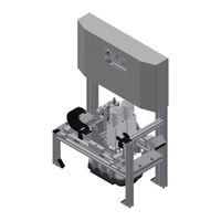
Festo CP Factory Manual (39 pages)
Application module iDrilling
Brand:
Festo
| Category:
Industrial Electrical
| Size: 2 MB
Table of Contents
Table of Contents
3
1 General Safety Instructions
5
Pictograms
6
Safety Sockets
7
Note to Electrical Access of Facility
7
Handling the System
8
Dangers in Handling the Machine
8
Safety Precautions in Standard Operation
8
Dangers Due to Electric Current
8
Dangers Due to Pneumatic Energy
8
Maintenance - Servicing - Malfunction Removal
8
Organizational Measures
9
Personnel
9
Notes on Personnel
9
Training Operations
9
Outside Training Operations
9
Obligations of the Operating Company
9
Obligations of the Trainees
9
2 Introduction
10
Warranty and Liability
10
Important Notes
10
3 Technical Data
11
4 Design and Function
12
Transport
12
Set up
12
General Information
12
The Application Module Idrilling
13
Function
15
Process Description
16
Electrical Connections
17
CECC I/O Assignment
17
5 Start up
19
Workstation
19
Mechanical Setup
19
Connection of Application Module
20
Pneumatic Port of Application Module
22
Electrical Connection of Application Modules
22
Adjusting the Sensors
23
Through-Beam Sensor (Workpiece Detection)
23
Proximity Switch (X-Axis Cylinder)
25
Proximity Switch (Z-Axis)
27
Adjusting the One-Way Flow Control Valves
29
Visual Inspection
30
6 Operation
31
General Operating Instructions
31
Conduct Instructions
31
Operating Instructions
31
Sequence Description of the Application Module Drilling
31
Setting the Application Module Drilling at HMI
35
Transitions of the Application Module
37
Parameter of Application
38
Advertisement
Related Products
Festo CP Factory Linear
Festo CP Factory Shunt
Festo CP Factory Bypass
festo Compact Performance CP-FB6-E
Festo CP-FB11-E
Festo CP-FB13-E
Festo CP-FB5-E
Festo CP-FB8
Festo CP-FB8-E
Festo CP-FB08-03
Festo Categories
Industrial Equipment
Control Unit
Controller
Touch terminals
DC Drives
More Festo Manuals
Login
Sign In
OR
Sign in with Facebook
Sign in with Google
Upload manual
Upload from disk
Upload from URL