Festo CP Factory Manual
Basic module branch
Hide thumbs
Also See for CP Factory:
- Manual (126 pages) ,
- Original operating instructions (90 pages) ,
- Manual (39 pages)
Table of Contents

Subscribe to Our Youtube Channel
Related Manuals for Festo CP Factory


Summary of Contents for Festo CP Factory
- Page 1 CP Factory ® Manual Basic module branch Festo Didactic CP Factory 02/2018...
- Page 2 Festo Didactic accepts no liability for injury or harm to trainees, the training company and/or any third parties which may occur when the installation is used beyond a genuine training situation, except Festo Didactic has caused such injury or harm intentionally or by grossly negligence.
-
Page 3: Table Of Contents
3.7 Adjusting the sensors _________________________________________________________________ 39 3.7.1 Proximity switch (stopper Identsensor) _______________________________________________ 39 3.7.2 Proximity switch (stopper cylinder) ___________________________________________________ 41 3.7.3 Proximity switch (branch cylinder) ___________________________________________________ 43 3.8 Adjusting the one-way flow control valves _________________________________________________ 45 © Festo Didactic CP Factory ° basic module branch... - Page 4 5.8 Mechanic components ________________________________________________________________ 110 5.8.1 Motor of Conveyor _______________________________________________________________ 110 5.8.2 The stopper unit _________________________________________________________________ 111 5.8.3 The branch ______________________________________________________________________ 113 5.8.4 Transportation of the Basic Module branch ___________________________________________ 114 © Festo Didactic CP Factory ° Basic module branch...
-
Page 5: General Safety Instructions
The protective ground must always be contacted first (before voltage) and must only be separated last (after voltage separation). • If not specified differently in the technical data, the device does not have an integrated fuse. © Festo Didactic CP Factory ° basic module branch... -
Page 6: Pictographs
Here you find important information for an appropriate handling of the machine. Disregarding this symbol may lead to malfunctions at the machine or in its surrounding area. Information This means that you obtain tips for the use and especially useful information. © Festo Didactic CP Factory ° Basic module branch... -
Page 7: Safety Terminal Sockets
(green-yellow) signal input/signal output (black) The specified protection categories and the safety can only been guaranteed when using Festo Didactic safety laboratory cables. Any damaged or faulty safety laboratory cables have to be blocked instantly and to be removed from the training area. -
Page 8: Handling The System
Please check that all screw connections which have been loosened during the maintenance, servicing or repair works are firmly seated. 1.4.6 Organizational measures All existing safety equipment has to be checked regularly. © Festo Didactic CP Factory ° Basic module branch... -
Page 9: Staff
Before they start work, all persons in charge of works at the system commit themselves to: • read the safety chapter and the warnings in this manual, • observe the basic principles about work safety and accident prevention. © Festo Didactic CP Factory ° basic module branch... -
Page 10: Introduction
Festo Didactic herewith rules out any legal responsibility for damages of the trainee, the training company and/or a third party which might occur when using the system beyond a genuine training situation, unless the damage has been caused by Festo Didactic intentionally or due to gross negligence. -
Page 11: Resources
The training equipment of the system consists of several resources. They are used depending on the process selection. The following resources are available: Pallet carrier These pallet carriers are available for transporting the pallets. Pallet These pallets are available for receiving always one workpiece. © Festo Didactic CP Factory ° basic module branch... - Page 12 CP fuse on the right CP part fuse on the right no 213 no 1213 CP fuses both CP part both fuses no 214 no 1214 CP part customer no 1210 freely selectable © Festo Didactic CP Factory ° Basic module branch...
-
Page 13: Design And Function
You have to see for an appropriate distance between the system and the wall. Keep away any dust from the station resulting from construction works (covering). © Festo Didactic CP Factory ° basic module branch... -
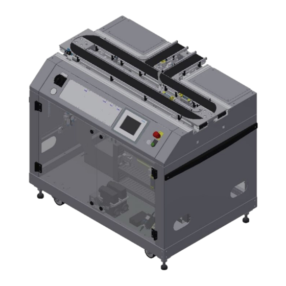
Page 14: The Basic Module Branch
The carriers are equipped with a read/write ID system. This ID system represents a very important part of the CP Factory System. The carriers are written with the current data of the workpiece to be transported. Thus all information required for the process is carried together with the workpiece/ carrier and is available at every operating position. - Page 15 Conveyor outward transfer Branch outward transfer Stopper unit back side Conveyor rear side Corner pulley/no other module attached Emergency stop button Controller on pushbutton E-Board Pressure switches (option for energy monitoring) © Festo Didactic CP Factory ° basic module branch...
-
Page 16: Mechanical Construction
Construction of the branch module - example Position Designation Branchs are in the position “do not transfer workpiece carriers outward” Branchs are in the position „transfer workpiece carriers outward/inward“ (branch is optional) © Festo Didactic CP Factory ° Basic module branch... - Page 17 Position Designation Operation as single station / not put together Operation as single station / stations are put together Operation in combination with an additional station © Festo Didactic CP Factory ° basic module branch...
- Page 18 Design and function Mounting as a single station – example Position Designation Corner pulley – the pallet carrier is reversed from one conveyor to the other conveyor on the branch module © Festo Didactic CP Factory ° Basic module branch...
- Page 19 Corner pulley – the workpiece carrier is reversed from one conveyor to the other conveyor on the module. The corner pulley and the support plate have only been put together and can easily be exchanged without tools. © Festo Didactic CP Factory ° basic module branch...
-
Page 20: Supply Of The Branch Module
CP Factory supply Position Description Inlet port for connection tube with voltage, communication and pneumatics Connection plug K2-XZ1 Connection plug K2-XZ2 Outlet port for the connection tube of a further module © Festo Didactic CP Factory ° Basic module branch... - Page 21 Design and function Position Description Emergency chain linking Pressure Network 400 V © Festo Didactic CP Factory ° basic module branch...
-
Page 22: Electrical Assembly
The branch module has got an electric board on the front side for the electrical components of the module. This electric board has been mounted in the right part of the housing. Electric board front side Beispiel © Festo Didactic CP Factory ° Basic module branch... - Page 23 Design and function Electric board front side with Siemens controller © Festo Didactic CP Factory ° basic module branch...
- Page 24 Start-up current limiter K1-QA2 Kaleja M-MZS-4-30 / 06.05.020 Start-up current limiter K1-QA3 Kaleja M-MZS-4-30 / 06.05.020 Start-up current limiter K1-QA4 Kaleja M-MZS-4-30 / 06.05.020 Ethernet switch K1-XF1 Siemens Scalance XB008 / 6GK5008-OBAOO-1AB2 © Festo Didactic CP Factory ° Basic module branch...
- Page 25 Design and function Electric board front side with Festo controller © Festo Didactic CP Factory ° basic module branch...
- Page 26 Start-up current limiter K1-QA3 Kaleja M-MZS-4-30 / 06.05.020 Start-up current limiter K1-QA4 Kaleja M-MZS-4-30 / 06.05.020 Ethernet switch K1-XF1 Siemens Scalance XB008 / 6GK5008-OBAOO-1AB2 Analog Terminal K1-XD16A UM 45-D15SUB/B I/O Terminal K1-XD15 © Festo Didactic CP Factory ° Basic module branch...
-
Page 27: Wiring Diagram
Design and function 3.5.1 Wiring Diagram Wiring diagram with Siemens controller © Festo Didactic CP Factory ° basic module branch... - Page 28 Design and function Wiring diagram with festo controller © Festo Didactic CP Factory ° Basic module branch...
-
Page 29: Emergency-Stop Structure
Emergency-stop pushbutton F2-FQ1 / to emergency stop board X4:1: X4:3; X4:5; X4:7 Reset Pushbutton 1S2 / to PNOZ S33+S34; indicator light terminal strip 24VNA/0V+ Emergency stop board for emergency chain linking / F2-XZ2 Emergency stop Unit / F2-KF1 © Festo Didactic CP Factory ° basic module branch... - Page 30 F2-XZ2-X4 Terminal clips for control panel, power supply, Emergency-stop relay. Example for Emergency-stop linking with 3 modules © Festo Didactic CP Factory ° Basic module branch...
- Page 31 4. If the module has been connected with other modules, the emergency-stop is effective at all stations and must therefore be acknowledged at every station by pressing the illuminated push-button “Adjusting” and acknowledging the error at the HMi © Festo Didactic CP Factory ° basic module branch...
-
Page 32: Emergency-Stop With Central Control
At this module, you can click on the message line at the top at the HMI, where the error message will be displayed in the main window. © Festo Didactic CP Factory ° Basic module branch... - Page 33 HMI with the illuminated pushbutton “adjusting” and by acknowledging the error at the HMI. ? © Festo Didactic CP Factory ° basic module branch...
-
Page 34: Connection Of Application Module
Put in slot nuts Then you install the application module. The slot nuts must be placed now under the mounting brackets so that the screws can be fixed. © Festo Didactic CP Factory ° Basic module branch... - Page 35 Please make sure that the workpieces can be transferred correctly like here at the application module magazine. Once the position has been fixed, you only have to tighten the screws and to put the covers on the mounting brackets. © Festo Didactic CP Factory ° basic module branch...
-
Page 36: Pneumatic Port Of Application Module
Pneumatic port is done on the principle of the following sketch. The application module is connected from the valve terminal to the on-off valve at the conveyor. You only have to plug the tube (nominal size 4) into the QS plug. Pneumatic connection of the application module © Festo Didactic CP Factory ° Basic module branch... -
Page 37: Electrical Connection Of Applications
If an application module has more than 8 I / O, the cable of the second I / O box is connected to the I / O terminal XMB on the electric board. Electrical connection example with Festo controller © Festo Didactic CP Factory ° basic module branch... -
Page 38: Commissioning
3.6.2 Electrical commissioning Now the module must be supplied with electric voltage (400 V). The voltage has to be provided by the customer. Furthermore, an expert installation must be guaranteed. © Festo Didactic CP Factory ° Basic module branch... -
Page 39: Adjusting The Sensors
Sensor stopper identify sensor / 150395 (SIEN-M8NB-PS-S-L) 1 position (BG21/BG31/BG41) 2 position (BG22/BG32/BG42) 3 position (BG23/BG33/BG43) 4 position (BG24/BG34/BG44) Screw to clamp the sensor The proximity switches are used for controlling the pallet. © Festo Didactic CP Factory ° basic module branch... - Page 40 5. Tighten the locking screw of the proximity switch with an Allen key SW 1,3. 6. Check the position of the proximity switch by repeated removing the pallet. Documents • Data sheets / operating instructions Proximity Switch 150395 (SIEN-M8NB-PS-S-L) © Festo Didactic CP Factory ° Basic module branch...
-
Page 41: Proximity Switch (Stopper Cylinder)
(BG20) / (BG30) / (BG30) / (BG40) The proximity switches are used for controlling the end position of the cylinder for the stopper. The proximity switches react to a permanent magnet on the piston of the cylinder. © Festo Didactic CP Factory ° basic module branch... - Page 42 5. Tighten the locking screw of the proximity switch with an Allen key SW 1,3. 6. Check the position of the proximity switch by repeated test runs of the cylinder. Documents • Data sheets / operating instructions Proximity Switch 574334 (SMT-8M-A-PS-24V-E-0,3-M8D) © Festo Didactic CP Factory ° Basic module branch...
-
Page 43: Proximity Switch (Branch Cylinder)
(BG31) The proximity switches are used for controlling the end position of the cylinder for the branch. The proximity switches react to a permanent magnet on the piston of the cylinder. © Festo Didactic CP Factory ° basic module branch... - Page 44 5. Tighten the locking screw of the proximity switch with an Allen key SW 1,3. 6. Check the position of the proximity switch by repeated test runs of the cylinder. Documents • Data sheets / operating instructions Proximity Switch 551373 (SMT-10M-PS-24V-E-2,5-L-OE) © Festo Didactic CP Factory ° Basic module branch...
-
Page 45: Adjusting The One-Way Flow Control Valves
Design and function 3.8 Adjusting the one-way flow control valves One-way flow control valves Description One-way flow control valves GRLA for stopper cylinder One-way flow control valves GRLA for stopper cylinder © Festo Didactic CP Factory ° basic module branch... - Page 46 Design and function One-way flow control valves Description One-way flow control valves GRLA for branch cylinder One-way flow control valves GRLA for branch cylinder © Festo Didactic CP Factory ° Basic module branch...
-
Page 47: Visual Inspection
2. The module is supplied by about 6 bar compressed air. On initial start-up, please pay attention to slowly increasing the pressure (herewith unpredictable events are prevented). Now you can work with the modules. © Festo Didactic CP Factory ° basic module branch... -
Page 48: Operation
The systems may only be operated by instructed persons. • Operation has to be effected according to the manual. • Any uncontrolled pressing of the various switches/buttons of all control units has to be prevented. © Festo Didactic CP Factory ° Basic module branch... -
Page 49: The Control Units Of The Basic Module Branch
CP Factory control panel only at front side Position Description Main switch -QB1 Manometer Touch Panel – PH1 / Festo panel or Siemens panel possible Emergency- stop switch – F2-FQ1 Network socket- XPN3 Controller on pushbutton – F2-SF1 © Festo Didactic CP Factory ° basic module branch... -
Page 50: Touch Panel
Input current Current consumption (rated value) 0.5 A Starting current inrush I²t 0.5 A²·s Power Power consumption, typ. 12 W Processor Processor type Memory Flash Memory available for user data 12 Mbyte © Festo Didactic CP Factory ° Basic module branch... - Page 51 Operation Festo CDPX Panel © Festo Didactic CP Factory ° basic module branch...
- Page 52 UL us - Listed (OL) Ethernet PLC interface RS485 USB interface Ethernet interface RJ45 10/100 MBd Mounting type Front panel installation Materials note Conforms to RoHS Programming software Designer Studio © Festo Didactic CP Factory ° Basic module branch...
-
Page 53: Sequence Description Of The Branch Module
Operation 4.3 Sequence description of the branch module Position Description Sensor straight track passed Stopper branch feed in Branch Stopper basic track Sensor branch track Stopper branch © Festo Didactic CP Factory ° basic module branch... - Page 54 Operation Sequence description stopper feed in © Festo Didactic CP Factory ° Basic module branch...
- Page 55 Operation © Festo Didactic CP Factory ° basic module branch...
- Page 56 Operation © Festo Didactic CP Factory ° Basic module branch...
-
Page 57: Switching On The Station
3. The module/application module will execute the run until cycle end. During this time, the button Cycle End has got a red background. 4. The stoppers are extended. 5. The conveyors are stopped. © Festo Didactic CP Factory ° basic module branch... -
Page 58: Operating Modes
Operating the basic modules is always the same procedure. A basic module with the application module drilling serves as an example here. Any additional operating possibilities are described separately in the corresponding manuals. The operation is not depending on the type of the operating panel, Festo and Siemens Panels have got the same functions. -
Page 59: Menu Architecture From Operation Panel
Submenu in the main menu Changing content, depending on the main menu Changing content, depending on the main or submenu Announcement of operation mode automatic or set up Announcement of default or MES Mode © Festo Didactic CP Factory ° basic module branch... -
Page 60: Menu Navigation
If you click on the blue marked field (no matter where you are in the menu), the following window will open (Pos 2) Operating window – the operating window is always the same and allows a fast operating of the station © Festo Didactic CP Factory ° Basic module branch... -
Page 61: Display Operation Modus
In the upper right-hand area, the order data of the workpiece carrier are displayed in the MES mode, while the RFID status code is displayed in the default mode. The status of the application is displayed in the lower right area, which is independent of the selected mode. © Festo Didactic CP Factory ° basic module branch... -
Page 62: Operation Mode Home
End Button: The currently active operating mode is stopped here. Select the mode: Default - Automatic sequence is executed with the stored transitions MES software is fully controlled by MES software © Festo Didactic CP Factory ° Basic module branch... - Page 63 Area Order Carrier ST2 - the information provided by MES are standing on the workpiece carrier Carrier ID: Carrier number ONo: Order number OPos: Order position PNo: Part number OpNo: Operation number ResID: Resource ID © Festo Didactic CP Factory ° basic module branch...
- Page 64 Operation Submenu overview Default Mode © Festo Didactic CP Factory ° Basic module branch...
- Page 65 RFID condition code with the settings of the "Init" line of the transition table. Number: Set: determines in this context, how many goods carriers should be initialized according to the above procedure. Act: Shows how many goods carriers have been initialized. © Festo Didactic CP Factory ° basic module branch...
- Page 66 Click on the button "User Dialog" to open the following window. If you click on the User or Password fields, the input window opens and the user data can be entered. © Festo Didactic CP Factory ° Basic module branch...
- Page 67 Operation Here the user data can be entered, confirm with the return key. © Festo Didactic CP Factory ° basic module branch...
-
Page 68: Operating Mode Setup
Sensor BG26 Display conveyor input (light up green when active) Sensor BG27 Display conveyor output (light up green when active) Sensor BG56 Display conveyor input (light up green when active) Sensor BG57 Display conveyor output (light up green when active) © Festo Didactic CP Factory ° Basic module branch... - Page 69 Sensor BG26 Display conveyor input (light up green when active) Sensor BG27 Display conveyor output (light up green when active) Sensor BG56 Display conveyor input (light up green when active) Sensor BG57 Display conveyor output (light up green when active) © Festo Didactic CP Factory ° basic module branch...
- Page 70 Delete data: all data in the input mask is deleted - not directly on the RFID (for easier entry) Area Display of the active sensors (lit green when active) and actuators (lit orange if active) on the stopper Display of the RFID read status © Festo Didactic CP Factory ° Basic module branch...
- Page 71 Delete data: all data in the input mask is deleted - not directly on the RFID (for easier entry) Area Display of the active sensors (lit green when active) and actuators (lit orange if active) on the stopper Display of the RFID read status © Festo Didactic CP Factory ° basic module branch...
- Page 72 Sender: Sensor GF35 blue if active (send signal to Robotino - Robotino must be activated) Receiver: Sensor KG35 green if active (Robotino detected) Area Display of the active sensors (lit green when active) and actuators (lit orange if active) on the stopper © Festo Didactic CP Factory ° Basic module branch...
- Page 73 Operation Setup – Shunt Position number description Area Display of the active sensors (lit green when active) and actuators (lit orange if active) on the stopper © Festo Didactic CP Factory ° basic module branch...
-
Page 74: Operation Mode Parameters
To set up the application module, the application module must be set to setup mode. 1. On the Start screen, click Setup Change to parameter page (1) and select application (2). © Festo Didactic CP Factory ° Basic module branch... - Page 75 In the case of an application without its own intelligence, this is adopted by the controller of the basic module and no check is to be made. © Festo Didactic CP Factory ° basic module branch...
- Page 76 The transitions of all other application modules can be found in the corresponding manuals of the application modules. Submenu transitions 2 If the transitions 2 submenu is selected, the transitions of the points are displayed. © Festo Didactic CP Factory ° Basic module branch...
- Page 77 If no workpiece is detected on the belt via the sensors, the belt is switched off Stopper 1: Check the jam at the belt outlet: The carrier is only released from the stopper if the belt is not occupied at the belt outlet. © Festo Didactic CP Factory ° basic module branch...
- Page 78 AS/RS from where products are released. Option docking with robotino activated: If a robotino is to pick up / deliver the carrier at the branch, this option must be activated with a hock. © Festo Didactic CP Factory ° Basic module branch...
-
Page 79: Operation Mode System - Settings
Display date and time of the PLC Display date and time of the HMI touch panel Display of the MES IP address additionally the IP of the MES can be set here. (Password protected) User: festo, PW: festo) Input fields for your own resource number, query port and status port of the MES connection Button set time &... -
Page 80: Operator Assistance And Simulate Application On Free Ap
Thus every free AP provides the following functions in default mode as well as in MES mode: 1. Generic sequence simulation 2. Operator assictance The application function is added with a fitted application module 1. Process simulation of the application 2. Operator assictance 3. Application Function © Festo Didactic CP Factory ° Basic module branch... -
Page 81: Generic Sequence Simulation
2. The processing time in this case is 10 sec. This can be set in the parameters. The current time is indicated by the bar in progress. At the end of the simulation, the return value is transferred to MES. 3. The carrier is released from the application position. © Festo Didactic CP Factory ° basic module branch... -
Page 82: Operator Assistance With Display Of Pictures
Back cover Extract Printed circuit board Assemble Front fuse (in direction of transport) Insert Rear fuse (in direction of transport) Apply Both fuses Rework Workpiece Reserve_7 Reserve_8 Reserve_8 Reserve_9 Reserve_9 Reserve_10 Reserve_10 © Festo Didactic CP Factory ° Basic module branch... - Page 83 4. If the worker has completed the task, he must press the Confirm button to complete the task. The data is transmitted to MES 5. The carrier is released from the application position. © Festo Didactic CP Factory ° basic module branch...
-
Page 84: Operator Assistance With Call Of Htm-Page
4. If the worker has completed the task, he must press the Confirm button to complete the task. The data is transmitted to MES 5. The carrier is released from the working position. © Festo Didactic CP Factory ° Basic module branch... -
Page 85: Automatic Operation
A gray button with a blue font indicates that this function is selectable. 1. Switch on the station and wait until HMi is raised. The following screen appears 2. Press Setup button © Festo Didactic CP Factory ° basic module branch... - Page 86 Operation 3. Select the default or MES mode, for the example the default mode is selected 4. Press the automatic button 5. Automatic is active © Festo Didactic CP Factory ° Basic module branch...
-
Page 87: Stop Automatic
Operation 4.8.2 Stop automatic 6. Press the cycle end button, the automatic sequence is immediately stopped. © Festo Didactic CP Factory ° basic module branch... -
Page 88: Manually Describe The Rfid Tag
5. The data of the RFID tag can be read out and displayed by pressing the "read" button. 6. Press the Delete Data button For easier input, all data is only deleted in the input mask, the data remains on the tag itself. © Festo Didactic CP Factory ° Basic module branch... - Page 89 Parameter 1 = 3 - Input of the 3 parameter value (e.g., 3 / both sides drilling) Parameters 2 - 4 - not used in this example 8. Press the "Write" button to write the changes made to the tag. © Festo Didactic CP Factory ° basic module branch...
-
Page 90: Components
• Anti-clockwise and clockwise rotation • Switch-over from high speed to the speed adjusted at the TR.1 • Port for limit switch for stop • Short-circuit proof and temperature protected • Limitation for starting circuit © Festo Didactic CP Factory ° Basic module branch... - Page 91 Any assembly position / DIN-rail assembly No / Yes Housing Plastic housing light grey Dimensions 59x77x50 Weight Approx. 100 Temperature / short guard Yes / Yes Connection type 4mm², 2,5mm² screw connection © Festo Didactic CP Factory ° basic module branch...
- Page 92 Control – K5-KF10 / Q0.2 / 0x:3 QA1 / X1:sl Transport 1: slow speed Conveyor motor DC / -XJM1:4 QA1 / X2:M1 Conveyor motor connection Conveyor motor DC / -XJM1:3 QA1 / X2:M2 Conveyor motor connection © Festo Didactic CP Factory ° Basic module branch...
- Page 93 Control – K5-KF10 / Q1.7 / 0x:8 QA4 / X1:sl Transport 4: slow speed Conveyor motor DC / -XJM3:4 QA4 / X2:M1 Conveyor motor connection Conveyor motor DC / -XJM3:3 QA4 / X2:M2 Conveyor motor connection © Festo Didactic CP Factory ° basic module branch...
-
Page 94: Plc Siemens
Components 5.2 PLC Siemens Siemens ET 200 SP / CPU 1512SP F-1PN For detailed information see electrical circuit diagram. © Festo Didactic CP Factory ° Basic module branch... -
Page 95: Plc Festo Cecc
Components 5.3 PLC Festo CECC The Festo controller is just one part (order number; 574418-CECC-LK) Festo CECC Position Description Comment USB interface For external memory Ethernet interface RJ 45 For external PC (for programming with CodeSys) or for external operation panel... -
Page 96: Turck Interface
Components 5.4 Turck Interface Turck interface For detailed information see electrical circuit diagram. © Festo Didactic CP Factory ° Basic module branch... -
Page 97: Scalance Ethernet Switch
Components 5.5 Scalance Ethernet Switch Siemens Scalence X208 Ehternet switch The SCALANCE X208 has eight RJ-45 jacks for the connection of end devices or other network segments. © Festo Didactic CP Factory ° basic module branch... - Page 98 If the autonegotiation function is disabled, the MDI/MDI-X auto crossover function is also inactive. This means it may be necessary to use a crossover cable. © Festo Didactic CP Factory ° Basic module branch...
- Page 99 Such a loop can lead to network overload and network failures. Auto polarity exchange If the pair of receiving cables are incorrectly connected (RD+ and RD- swapped over), the polarity is reversed automatically. © Festo Didactic CP Factory ° basic module branch...
-
Page 100: Rfid With Ethernet
Ethernet connection RSSD-RSSD 441-2M Ethernet connection RSSD-RSSD 441-2M Rotary coding switch for addressing RFID connection socket RK4.5T-5-RS4.5T/S2500 for read-write head 1 RFID connection socket RK4.5T-5-RS4.5T/S2500 for read-write head 2 Power supply Power supply © Festo Didactic CP Factory ° Basic module branch... - Page 101 Bit 1 Bit 0 Control word channel 0- low byte Chanel 0 Control word channel 0- high byte Control word channel 1- low byte Chanel 1 Control word channel 1- high byte © Festo Didactic CP Factory ° basic module branch...
- Page 102 Ethernet cable from Turck module to controller (via Scalance) Turck cable from Turck read-write head to Turck module Turck cable from Turck read-write head to Turck module Turck Ethernet module with RFID interface (equipment identifier K2-KF80) © Festo Didactic CP Factory ° Basic module branch...
- Page 103 The Turck RFID read-write head is mounted on the stopper unit on the conveyor. Its designation is TB-M18-H1147. Name Operating voltage 10…30 VDC DC rated operating current 0-80 mA Operating voltage Data transfer Inductive coupling Working frequency 13,56 MHz Read-write distance max. 30 mm © Festo Didactic CP Factory ° basic module branch...
-
Page 104: Rfid With Canbus
1 LED green flashing light Operational mode Displays / operating elements 1 LED Red flashing light Error 1 LED yellow continuous light tag communication Connection M12 connector Not used Wiring CAN_H CAN_L © Festo Didactic CP Factory ° Basic module branch... -
Page 105: Mini Terminal
Pin 14 and Pin 15 Pin allocation M8 socket corresponding to IEC 947-5-2 • slots 0 to 11 • Signal line socket 4 • DC 24V socket 1 • socket 3 © Festo Didactic CP Factory ° basic module branch... - Page 106 Downstream station free 2 - option Bit 9 Station occupied 2 - option Bit 10 Downstream station free 3 - option Bit 11 Station occupied 3 - option +24 V 14 and 15 © Festo Didactic CP Factory ° Basic module branch...
- Page 107 Identity sensor 3 / -BG53 Bit 7 Reserve Bit 8 Identity sensor 4 / -BG54 Bit 9 Conveyor infeed / BG56 Bit 10 Reserve Bit 11 Conveyor outlet / BG57 +24 V 14 and 15 © Festo Didactic CP Factory ° basic module branch...
- Page 108 PIN 9 Inscription label Mounting hole M3 OUT 0 IN 0 OUT 1 IN 1 OUT 2 IN 2 OUT 3 IN 3 OUT 4 IN 4 OUT 5 IN 5 © Festo Didactic CP Factory ° Basic module branch...
-
Page 109: Sys Link Interface
Input EX.3 Output AX.4 InputEX.4 Output AX.5 Input EX.5 Output AX.6 InputEX.6 Output AX.7 Input EX.7 Power Supply Power Supply Power Supply Power Supply Power Supply Power Supply Power Supply Power Supply © Festo Didactic CP Factory ° basic module branch... -
Page 110: Mechanic Components
Rated torque MN [Nm] Starting torque MA [Nm] Gear ratio i 53/2 Connection resistance 2 vanes R [m 3400 Connection resistance 4 vanes R [m 3000 Protection class IP 30 Weight [kg] © Festo Didactic CP Factory ° Basic module branch... -
Page 111: The Stopper Unit
Pallet available Ident sensor 4 / Ordernumber 150395 / SIEN-M8NB-PS-S- Stopping unit Stopper cylinder / Ordernumber 157211 / AEVUZ-16-5-P-A Sensor Stopper lowered / Ordernumber 574334 / SMT-8M-A-PS-24V-E-0,3-M8D one-way flow control valve / Ordernumber. 193967 / GR-QS-4 © Festo Didactic CP Factory ° basic module branch... - Page 112 Components Diagram of pneumatics, Stopper Unit © Festo Didactic CP Factory ° Basic module branch...
-
Page 113: The Branch
Components 5.8.3 The branch Position Description BG45 – gate area free (straight) BG42 – gate area free (deflection) BG30 – outward transfer straight line BG31 – outward transfer bend off © Festo Didactic CP Factory ° basic module branch... -
Page 114: Transportation Of The Basic Module Branch
Basic Module ByPass easily to another place. Position Description Star knob for adjusting the height of the machine mount Roller Lock nut for locking the machine mount in the position required © Festo Didactic CP Factory ° Basic module branch... - Page 115 Components Festo Didactic SE Rechbergstraße 3 73770 Denkendorf Germany Internet: www.festo-didactic.com E-mail: did@de.festo.com © Festo Didactic CP Factory ° basic module branch...
Need help?
Do you have a question about the CP Factory and is the answer not in the manual?
Questions and answers