
Related Manuals for Vertiv NetSure 2100 Series


Summary of Contents for Vertiv NetSure 2100 Series
- Page 1 NetSure™ 2100 Series -48 VDC Power System User Manual Specification Number: 582138000 Model Number: 2100...
- Page 2 The information contained in this document is subject to change without notice and may not be suitable for all applications. While every precaution has been taken to ensure the accuracy and completeness of this document, Vertiv assumes no responsibility and disclaims all liability for damages resulting from use of this information or for any errors or omissions.
-
Page 3: Table Of Contents
Vertiv™ NetSure™ 2100 Series -48 VDC Power System User Manual TABLE OF CONTENTS Admonishments Used in this Document ..........................iv Important Safety Instructions ..............................v 1 Customer Documentation Package ..........................1 2 System Description ................................2 3 Operating Procedures ................................3 3.1 Controller and Rectifier ................................................ -
Page 4: Admonishments Used In This Document
Vertiv™ NetSure™ 2100 Series -48 VDC Power System User Manual Admonishments Used in this Document will likely DANGER! Warns of a hazard the reader be exposed to that will result in death or serious injury if not avoided. (ANSI, OSHA) -
Page 5: Important Safety Instructions
Vertiv™ NetSure™ 2100 Series -48 VDC Power System User Manual Important Safety Instructions Safety Admonishments Definitions Definitions of the safety admonishments used in this document are listed under “Admonishments Used in this Document” on page iv. Safety and Regulatory Statements Refer to Section 4154 (provided with your customer documentation) for Safety and Regulatory Statements. - Page 6 Vertiv™ NetSure™ 2100 Series -48 VDC Power System User Manual This page intentionally left blank. Proprietary and Confidential © 2022 Vertiv Group Corp.
-
Page 7: Customer Documentation Package
Vertiv™ NetSure™ 2100 Series -48 VDC Power System User Manual 1 Customer Documentation Package This document (UM582138000) provides User Instructions for the Vertiv™ NetSure™ 2100 Series -48 VDC Power System: Model 2100, Spec. No. 582138000. The complete Customer Documentation Package consists of…... -
Page 8: System Description
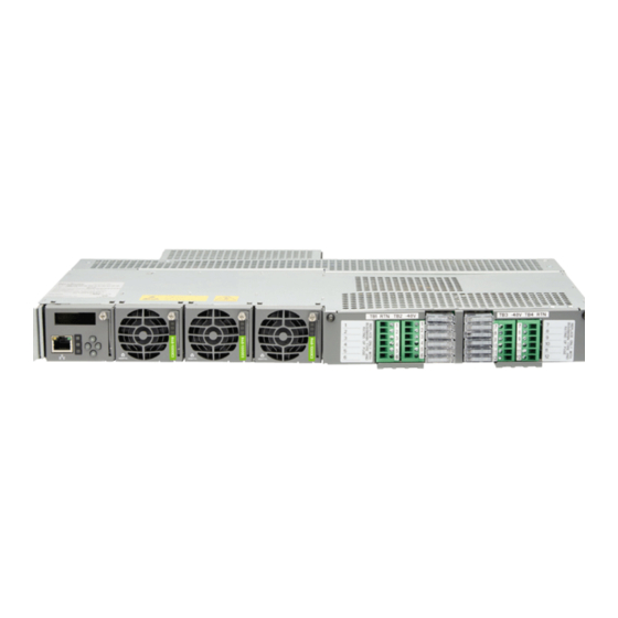
The Vertiv NetSure 2100 Series -48 VDC Power System consists of the following components mounted in a 19” or 23” wide relay rack or cabinet rack. Wall mounting options are also available. -
Page 9: Operating Procedures
Vertiv™ NetSure™ 2100 Series -48 VDC Power System User Manual 3 Operating Procedures 3.1 Controller and Rectifier For operation instructions on these units, refer to the following documents. • Mini Control Unit Instructions: UM1M831ANA NOTE! The controller’s default “User Name” is "admin" and the default “Password” is “640275”. -
Page 10: Maintenance
Vertiv™ NetSure™ 2100 Series -48 VDC Power System User Manual 4 Maintenance 4.1 System Maintenance Procedures It is recommended to perform the maintenance procedures listed in Table 4.1 every 6 months to ensure continual system operation. Table 4.1 Maintenance Procedures to be Performed at 6-Month Intervals... -
Page 11: Troubleshooting And Repair
Vertiv™ NetSure™ 2100 Series -48 VDC Power System User Manual 5 Troubleshooting and Repair 5.1 Contact Information Refer to Section 4154 (provided with your customer documentation) for support contact information. 5.2 Controller and Rectifier For troubleshooting and repair instructions on these units, refer to the following documents. -
Page 12: Clearing A Rectifier Communications Fail Alarm After Removing A Rectifier
Vertiv™ NetSure™ 2100 Series -48 VDC Power System User Manual of 10 amps. If one or more rectifiers are removed or fails it will take several seconds for the individual set points to the remaining rectifiers to be reset. In the example given, if one rectifier is removed the current limit set point will drop to 20 amps (10 amps times two remaining rectifiers) until the controller can send updated set points to the remaining rectifiers. -
Page 13: Replacing A Gmt Distribution Fuse
Vertiv™ NetSure™ 2100 Series -48 VDC Power System User Manual 5.6.3 Replacing a GMT Distribution Fuse Replace distribution devices with the same type and rating. Refer to system application guide SAG582138000 for part numbers. Procedure Refer to Figure 5.1, Figure 5.2, Figure 5.3, or Figure 5.4 and replace the fuse. Ensure a safety fuse cover is installed on the replacement fuse, as shown in Figure 5.5. - Page 14 Vertiv™ NetSure™ 2100 Series -48 VDC Power System User Manual Figure 5.3 GMT Distribution Fuse Replacement (List BA) Front GMT Fuse Safety Cover Figure 5.4 GMT Distribution Fuse Replacement (List BB) Front GMT Fuse Safety Cover Figure 5.5 Installation of Safety Fuse Covers...
-
Page 15: Replacing A Bullet Nose Circuit Breaker
Vertiv™ NetSure™ 2100 Series -48 VDC Power System User Manual 5.6.4 Replacing a Bullet Nose Circuit Breaker Replace distribution devices with the same type and rating. Refer to system application guide SAG582138000 for part numbers. Procedure Operate the defective circuit breaker to the OFF position. - Page 16 Vertiv™ NetSure™ 2100 Series -48 VDC Power System User Manual Figure 5.6 Replacing a Bullet Nose Circuit Breaker (List CA) Front Insert these terminals into corresponding sockets on distribution unit. Insert these terminals into corresponding Shorter Side Longer Side Shorter Side...
- Page 17 Vertiv™ NetSure™ 2100 Series -48 VDC Power System User Manual Figure 5.7 Replacing a Bullet Nose Circuit Breaker (List BB) Front Insert these terminals into corresponding sockets on distribution unit. Longer Side of Breaker Insert these terminals into corresponding sockets on distribution unit.
-
Page 18: Replacing A Compact Circuit Breaker
Vertiv™ NetSure™ 2100 Series -48 VDC Power System User Manual 5.6.5 Replacing a Compact Circuit Breaker Replace distribution devices with the same type and rating. Refer to system application guide SAG582138000 for part numbers. Procedure Operate the defective circuit breaker to the OFF position. - Page 19 Vertiv™ NetSure™ 2100 Series -48 VDC Power System User Manual Figure 5.9 Replacing a Compact Circuit Breaker (List BB) Front Insert these terminals (top and bottom) into corresponding sockets on distribution unit. Partially slide distribution Turn circuit breaker unit out of shelf to facilitate off before installing.
-
Page 20: Replacing The External Ib4 Assembly (If Furnished)
Vertiv™ NetSure™ 2100 Series -48 VDC Power System User Manual 5.6.6 Replacing the External IB4 Assembly (if furnished) DANGER! Adhere to the “Important Safety Instructions” starting on page v. WARNING! Circuit cards used in this system contain static-sensitive devices. Refer to Section 4154 (provided with your customer documentation) for static-sensitive device precautions. - Page 21 Vertiv™ NetSure™ 2100 Series -48 VDC Power System User Manual Figure 5.10 External IB4 Assembly USB-A Port 10M Ethernet (not used) Port (RJ-45) LAN Connection External IB4 Assembly USB-A Port 10M Ethernet (not used) Port (RJ-45) LAN Connection USB-B Port...
- Page 22 Vertiv™ NetSure™ 2100 Series -48 VDC Power System User Manual This page intentionally left blank. Proprietary and Confidential © 2022 Vertiv Group Corp.
- Page 23 Vertiv™ NetSure™ 2100 Series -48 VDC Power System User Manual Connect with Vertiv on Social Media https://www.facebook.com/vertivI https://www.instagram.com/vertiv/ https://www.linkedin.com/company/vertiv/ https://www.twitter.com/vertiv/ Proprietary and Confidential © 2022 Vertiv Group Corp.
- Page 24 Vertiv.com | Vertiv Headquarters, 1050 Dearborn Drive, Columbus, OH, 43085, USA © 2022 Vertiv Group Corp. All rights reserved. Vertiv™ and the Vertiv logo are trademarks or registered trademarks of Vertiv Group Corp. All other names and logos referred to are trade names, trademarks or registered trademarks of their respective owners. While every precaution has been taken to ensure accuracy and completeness here, Vertiv Group Corp.
Need help?
Do you have a question about the NetSure 2100 Series and is the answer not in the manual?
Questions and answers