
Related Manuals for Vertiv NetSure F1011259


Summary of Contents for Vertiv NetSure F1011259
- Page 1 NetSure™ External Distribution Box (EDB) Description and Installation Manual Specification Number: F1011259, F1011265, F1011266...
- Page 2 The information contained in this document is subject to change without notice and may not be suitable for all applications. While every precaution has been taken to ensure the accuracy and completeness of this document, Vertiv assumes no responsibility and disclaims all liability for damages resulting from use of this information or for any errors or omissions.
-
Page 3: Table Of Contents
Vertiv™ NetSure™ External Distribution Box (EDB) Description and Installation Manual TABLE OF CONTENTS Admonishments Used in this Document ..........................v Important Safety Instructions ..............................vi 1 About this Document ................................1 2 Product Description ................................1 General ........................................................1 Part Numbers ....................................................1 2.2.1 Enclosure .................................................. - Page 4 Vertiv™ NetSure™ External Distribution Box (EDB) Description and Installation Manual 9.4 Main Ground Bar ..................................................18 10 Cable Routing ..................................20 11 Making Electrical Connections ............................21 11.1 Important Safety Instructions ............................................21 11.2 General ....................................................... 21 11.3 Cable Routing ....................................................21 11.4 Sealing Cable Entries ................................................
-
Page 5: Admonishments Used In This Document
Vertiv™ NetSure™ External Distribution Box (EDB) Description and Installation Manual Admonishments Used in this Document will likely DANGER! Warns of a hazard the reader be exposed to that will result in death or serious injury if not avoided. (ANSI, OSHA) -
Page 6: Important Safety Instructions
Vertiv™ NetSure™ External Distribution Box (EDB) Description and Installation Manual Important Safety Instructions Safety Admonishments Definitions Definitions of the safety admonishments used in this document are listed under “Admonishments Used in this Document” on page v. You Must Follow Approved Safety Procedures DANGER! Performing the following procedures may expose you to hazards. - Page 7 Vertiv™ NetSure™ External Distribution Box (EDB) Description and Installation Manual General Safety Precautions The following precautions shall be observed at all time when handling and installing the enclosure: • Observe all safety precautions against personal injury and equipment damage. •...
- Page 8 Vertiv™ NetSure™ External Distribution Box (EDB) Description and Installation Manual Specific Safety Precautions DANGER! ELECTRICAL HAZARD The equipment shall be installed and serviced by trained service personnel in accordance with the applicable requirements of the current edition of the American National Standards Institute (ANSI) approved National Fire Protection Association's (NFPA) National Electrical Code (NEC) (NFPA 70) or Canadian Electrical Code;...
- Page 9 Vertiv™ NetSure™ External Distribution Box (EDB) Description and Installation Manual WARNING! RISK OF HAZARDOUS SUBSTANCES After handling of the enclosure or any such component, such as batteries, cables, busbars, etc., always wash hands immediately after. DANGER! RISK OF CHEMICAL EXPOSURE A battery can present harmful chemicals.
- Page 10 Vertiv™ NetSure™ External Distribution Box (EDB) Description and Installation Manual This page intentionally left blank. Proprietary and Confidential © 2022 Vertiv Group Corp.
-
Page 11: About This Document
Figure 2.1 for overall views of the enclosure. The Vertiv™ NetSure™ External Distribution Box (EDB) is to be mounted on the side of a companion enclosure made of a minimum of 0.125-inch aluminum or 14-gauge galvanized steel. A companion enclosure is a Vertiv™ XTE series enclosure equipped with a Vertiv™... - Page 12 Vertiv™ NetSure™ External Distribution Box (EDB) Description and Installation Manual Figure 2.1 Vertiv™ NetSure™ External Distribution Box (EDB) Overall Views Front Front Rear Rear Proprietary and Confidential © 2022 Vertiv Group Corp.
-
Page 13: Circuit Breakers
Vertiv™ NetSure™ External Distribution Box (EDB) Description and Installation Manual 2.2.2 Circuit breakers Refer to Table 2.2 for the part numbers of compatible circuit breakers to be used in the enclosure’s distribution panels. Each distribution panel holds up to twenty-six (26) single-pole bullet nose-type load distribution circuit breakers. -
Page 14: Environmental
2.4.3 Compliance information The Vertiv™ NetSure™ External Distribution Box (EDB) complies with the following standards: • UL Listed to UL 62368-1 (2nd Edition), UL Subject 1801, and CAN/CSA C22.2 No. 62368-1-14 (2nd Edition) under Vertiv file no. E97066 (QPQY/QPQY7 categories). •... - Page 15 Vertiv™ NetSure™ External Distribution Box (EDB) Description and Installation Manual Figure 2.2 Enclosure Dimensions 40.00 9.12 60.82 Left Side Front Right Side (2) 3/4-inch trade-size knockouts Bottom (1.125-inch actual diameter). (8) 1.77-inch cable grommets. (4) 2-inch trade-size knockouts (10) 2.50-inch cable grommets.
-
Page 16: Enclosure Features And Options
Vertiv™ NetSure™ External Distribution Box (EDB) Description and Installation Manual Figure 2.3 Enclosure Mounting Dimensions 40.00 2.00 6.00 6.00 6.00 6.00 6.00 6.00 60.82 59.82 Front Notes: 1 x 0.438 (14-places) 1. All dimensions are in inches. 2.6 Enclosure Features and Options Perspective Views: Refer to Figure 2.4 for enclosure perspective views with major features identified. - Page 17 Vertiv™ NetSure™ External Distribution Box (EDB) Description and Installation Manual Front Doors: The enclosure has two (2) front environmentally sealed doors that provide access to the DC distribution chamber, fiber termination and storage chamber, and cable entry chamber. • The front doors securing mechanism is a swing handle with multi-point rod-latch mechanism.
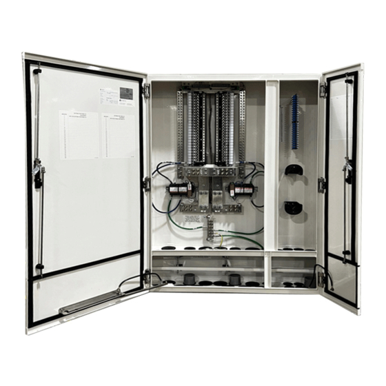
- Page 18 Vertiv™ NetSure™ External Distribution Box (EDB) Description and Installation Manual Figure 2.4 Perspective Views with Major Features Identified (cont’d on next page) Fiber Termination DC Distribution Fiber Storage Front Door Front Door Cable Entry (Splash Zone) Cable Entry Grommets Drain Holes Cable Entry Grommets Proprietary and Confidential ©...
- Page 19 Vertiv™ NetSure™ External Distribution Box (EDB) Description and Installation Manual Figure 2.4 Perspective Views with Major Features Identified (cont’d from previous page) Alarm Block (X2) 26-Position DC Distribution Panel (X2) Distribution Return Bar (X2) Input Return Bar (X2) LVD Contactor or Bypass Busbar Spec.
-
Page 20: Sequence Of Procedures
Vertiv™ NetSure™ External Distribution Box (EDB) Description and Installation Manual 3 Sequence of Procedures 3.1 General Perform the procedures in Table 3.1 (in the order listed) to fully install the enclosure. Other documents and manufacturer’s documents may be required to complete the installation of the system. This includes, but is not limited to: •... -
Page 21: Front Doors And Locks
Vertiv™ NetSure™ External Distribution Box (EDB) Description and Installation Manual 4 Front Doors and Locks 4.1 Important Safety Instructions DANGER! Adhere to the “Important Safety Instructions” starting on page vi. 4.2 Front Doors The enclosure front doors are equipped with swing handle, multi-point rod-latch systems. The swing handle latch includes provisions for a customer supplied padlock. - Page 22 Vertiv™ NetSure™ External Distribution Box (EDB) Description and Installation Manual Figure 4.1 Front Door Swing-Latch Front Left Side Door Front Right Side Door Padlock Hasp Door Swing Handle Security Lock Locked Position Open Position Proprietary and Confidential © 2022 Vertiv Group Corp.
- Page 23 Vertiv™ NetSure™ External Distribution Box (EDB) Description and Installation Manual Figure 4.2 Enclosure’s Left Side Front Door Wind Latch Wind Latch Wind Latch 90° 120° Wind Latch 90° Position 120° Position Proprietary and Confidential © 2022 Vertiv Group Corp.
-
Page 24: Installation Considerations
Vertiv™ NetSure™ External Distribution Box (EDB) Description and Installation Manual 5 Installation Considerations NOTE! If holes are drilled into the exterior of this enclosure and not filled using a seal tight connector, the manufacturer’s warranty will be void. 5.1 Installation Overview The following is the recommended sequence for the installation and start-up procedures. -
Page 25: Transportation And Storage
Vertiv™ NetSure™ External Distribution Box (EDB) Description and Installation Manual • Electrician’s insulated screwdrivers, Phillips, No. 1 and 2. • Electrician’s insulated screwdrivers, flat-blade, small and large. • Silicone sealant. • Duct putty. • NO-OX-ID-A or approved equivalent. NOTE! Outside the scope of this document, are the tools to fish, splice and terminate OSP Cables. -
Page 26: Inspecting And Unpacking The Enclosure At The Installation Site
Perform the following steps to install the enclosure on the outside of a companion enclosure. Procedure Prepare the companion enclosure per site requirements to allow the Vertiv™ NetSure™ External Distribution Box (EDB) to be attached to the outside of a side wall. Refer to Figure 2.3 on page 6 for mounting hole locations. - Page 27 Vertiv™ NetSure™ External Distribution Box (EDB) Description and Installation Manual Ensure that the circuit breaker is in the OFF position and is of the correct rating. Orient the circuit breaker as shown in Figure 8.1. Insert the terminals on the rear of the circuit breaker into their corresponding sockets on the distribution panel.
-
Page 28: Grounding The Enclosure
Vertiv™ NetSure™ External Distribution Box (EDB) Description and Installation Manual 9 Grounding the Enclosure 9.1 Important Safety Instructions DANGER! Adhere to the “Important Safety Instructions” starting on page vi. 9.2 General All enclosure grounding must be installed prior to turn up of enclosure. - Page 29 Vertiv™ NetSure™ External Distribution Box (EDB) Description and Installation Manual Figure 9.2 Enclosure Main Ground Bar Location Main Ground Bar 1/4-20 Bolt with washer 1/4” Flat Washer (Recommended Torque: 60 in-lbs.) Main Ground Bar Notes: 1. All dimensions are in inches.
-
Page 30: Cable Routing
Vertiv™ NetSure™ External Distribution Box (EDB) Description and Installation Manual 10 Cable Routing Cable entry/exit is made into a dedicated chamber at the bottom of the enclosure. Ten (10) 2.50-inch cable grommets and eight (8) 1.77-inch cable grommets are provided on the bottom of the enclosure for cable entry. There are four (4) 2-inch trade size knockouts provided for power cable entry and fiber exit, along with two (2) 3/4-inch trade size knockouts for alarm wiring. -
Page 31: Making Electrical Connections
Vertiv™ NetSure™ External Distribution Box (EDB) Description and Installation Manual 11 Making Electrical Connections 11.1 Important Safety Instructions DANGER! Adhere to the “Important Safety Instructions” starting on page vi. 11.2 General • The enclosure provides terminations for two (2) -48 VDC / -58 VDC input power sources (see Figure 2.4 on page 8). -
Page 32: Connecting Rrhs Cable Power Leads To The -48 Vdc / -58 Vdc Distribution Panels
Vertiv™ NetSure™ External Distribution Box (EDB) Description and Installation Manual fiber termination chamber of the enclosure as described in a subsequent procedure. Ensure adequate length of cable is pulled into the enclosure before performing the next step. For each cable, remove the cable sheath and terminate the ground wire to a tower cable ground bar located in the bottom chamber of the enclosure. - Page 33 Vertiv™ NetSure™ External Distribution Box (EDB) Description and Installation Manual Figure 11.1 DC Load Distribution Connections Front doors remove in illustration for clarity only. -48 VDC / -58 VDC Load and Return Connections 1/4-20 Studs on 5/8” Centers (Customer must supply or order additional hardware) Maximum Lug Width: 0.625 inches.
-
Page 34: Connecting Alarm And Lvd (Low Voltage Disconnect) Cables
Refer to Figure 11.2 for alarm block locations. For alarm and LVD connections, refer to Figure 11.3, Figure 11.4, and Figure 11.5. For connections to typical Vertiv™ Power Systems, refer to Figure 11.6, Figure 11.7, and Figure 11.8. Refer to the following procedure. - Page 35 Vertiv™ NetSure™ External Distribution Box (EDB) Description and Installation Manual Figure 11.3 Alarm Block Connections – F1011259 Proprietary and Confidential © 2022 Vertiv Group Corp.
- Page 36 Vertiv™ NetSure™ External Distribution Box (EDB) Description and Installation Manual Figure 11.4 Alarm Block Connections – F1011265 Proprietary and Confidential © 2022 Vertiv Group Corp.
- Page 37 Vertiv™ NetSure™ External Distribution Box (EDB) Description and Installation Manual Figure 11.5 Alarm Block Connections – F1011266 Proprietary and Confidential © 2022 Vertiv Group Corp.
- Page 38 Vertiv™ NetSure™ External Distribution Box (EDB) Description and Installation Manual Figure 11.6 Typical Power System LVD Connections to Alarm BLOCK 2 (Vertiv™ NetSure™ 512 DC Power System, Spec. No. 582137000 List 27, 582137000ZZ007 Shown. Others Similar.) Factory Wiring Side Block 1 and Block 2: Wire Size Capacity: 20 AWG to 22 AWG.
- Page 39 Vertiv™ NetSure™ External Distribution Box (EDB) Description and Installation Manual Figure 11.7 Typical Power System LVD Connections to Alarm BLOCK 2 (Vertiv™ NetSure™ 5100 DC Power System, Spec. No. 582137100 List 26, 582137100ZZ028 Shown. Others Similar.) Factory Wiring Side Block 1 and Block 2: Wire Size Capacity: 20 AWG to 22 AWG.
- Page 40 Vertiv™ NetSure™ External Distribution Box (EDB) Description and Installation Manual Figure 11.8 Typical Power System LVD Connections to Alarm BLOCK 2 (Vertiv™ NetSure™ 7100 DC Power System, Spec. No. 582127000203 Shown. Others Similar.) Factory Wiring Side Block 1 and Block 2: Wire Size Capacity: 20 AWG to 22 AWG.
-
Page 41: Connecting Fiber Cables To The Enclosure
Vertiv™ NetSure™ External Distribution Box (EDB) Description and Installation Manual Alarm Circuit Cards P/N 541183 Description (For Reference Only) Two (2) alarm cards (one per distribution panel) are provided to connect circuit breaker alarms into the alarm circuits of the companion enclosure. -
Page 42: Installing Fiber Cables
Vertiv™ NetSure™ External Distribution Box (EDB) Description and Installation Manual 11.7.2 Installing Fiber Cables Refer to the following procedure. Procedure NOTE! Minor excess fiber trunk cable can be coiled on the spool; however, any large bundle of excess shall be stored in an external fiber management box. -
Page 43: Sealing Enclosure Cable Entries
Vertiv™ NetSure™ External Distribution Box (EDB) Description and Installation Manual Figure 11.10 -48 VDC / -58 VDC Input Power Connections Front doors remove in illustration for clarity only. -48 VDC / -58 VDC Input Connections 3/8-16 Studs on 1” Centers (Customer must supply additional hardware) Maximum Lug Width: 1.06 inches. -
Page 44: Initial Power Up
Vertiv™ NetSure™ External Distribution Box (EDB) Description and Installation Manual 13 Initial Power Up 13.1 Important Safety Instructions DANGER! Adhere to the “Important Safety Instructions” starting on page vi. 13.2 Prerequisite All procedures and safety notices previous to this section have been observed, with the respect to the installation of the enclosure, installation of circuit breakers, and making electrical connections. -
Page 45: Routine Maintenance
Vertiv™ NetSure™ External Distribution Box (EDB) Description and Installation Manual 14.4 Routine Maintenance 14.4.1 Freezing rain and ice A primary issue with freezing rain and ice is: • Difficulty of access to the inside of the enclosure. The selected lock hasp has been designed to minimize hidden ice build-up and provide for the removal of ice. -
Page 46: Dc Power, Outdoor Enclosure & Service Contacts
Vertiv™ NetSure™ External Distribution Box (EDB) Description and Installation Manual 16 DC Power, Outdoor Enclosure & Service Contacts CUSTOMER SERVICE (PRE-SHIPMENT) Email CustomerService.ESNA@Vertiv.com Call Customer Service for purchase order status, expediting requests and order tracking. Phone 1.800.800.1280 option 1 CUSTOMER SUPPORT CENTER (POST-SHIPMENT) Email ESNACustomerSupportCenter@Vertiv.com... - Page 47 Vertiv™ NetSure™ External Distribution Box (EDB) Description and Installation Manual Connect with Vertiv on Social Media https://www.facebook.com/vertivI https://www.instagram.com/vertiv/ https://www.linkedin.com/company/vertiv/ https://www.twitter.com/vertiv/ Proprietary and Confidential © 2022 Vertiv Group Corp.
- Page 48 Vertiv.com | Vertiv Headquarters, 1050 Dearborn Drive, Columbus, OH, 43085, USA © 2022 Vertiv Group Corp. All rights reserved. Vertiv™ and the Vertiv logo are trademarks or registered trademarks of Vertiv Group Corp. All other names and logos referred to are trade names, trademarks or registered trademarks of their respective owners. While every precaution has been taken to ensure accuracy and completeness here, Vertiv Group Corp.
Need help?
Do you have a question about the NetSure F1011259 and is the answer not in the manual?
Questions and answers