Table of Contents
Advertisement
Quick Links
Advertisement
Table of Contents

Related Manuals for Vertiv NetSure 588820200SK001


Summary of Contents for Vertiv NetSure 588820200SK001
- Page 1 NetSure™ -48 VDC Battery Tray Kit Installation Manual Kit Specification Number: 588820200SK001, 588820200SK002, 588820200SK003, 588820200SK004, 582136700SK001, 582136700SK002, 582136700SK007, 582136700SK008, 582137100SK001, 60075254, 60075329...
- Page 2 The information contained in this document is subject to change without notice and may not be suitable for all applications. While every precaution has been taken to ensure the accuracy and completeness of this document, Vertiv assumes no responsibility and disclaims all liability for damages resulting from use of this information or for any errors or omissions.
-
Page 3: Table Of Contents
Vertiv™ NetSure™ -48 VDC Battery Tray Kit Installation Manual TABLE OF CONTENTS Admonishments Used in this Document ..........................iv Important Safety Instructions ..............................v Safety Admonishments Definitions ............................................v General Safety ......................................................v Voltages..........................................................v AC Input Voltages ................................................... v DC Output and Battery Voltages .......................................... -
Page 4: Admonishments Used In This Document
Vertiv™ NetSure™ -48 VDC Battery Tray Kit Installation Manual Admonishments Used in this Document will likely DANGER! Warns of a hazard the reader be exposed to that will result in death or serious injury if not avoided. (ANSI, OSHA) could... -
Page 5: Important Safety Instructions
DANGER! Installation of this kit should only be performed by a qualified technician following approved safety procedures. If a qualified technician is not available, arrangements can be made with a Vertiv service facility to have the kit installed. DANGER! YOU MUST FOLLOW APPROVED SAFETY PROCEDURES. -
Page 6: Battery
Vertiv™ NetSure™ -48 VDC Battery Tray Kit Installation Manual Battery Refer to the battery manufacturer documentation for specific battery safety instructions. The following are general guidelines. WARNING! Correct polarity must be observed when connecting battery leads. WARNING! Special safety precautions are required for procedures involving handling, installing, and servicing batteries. -
Page 7: Personal Protective Equipment (Ppe)
Vertiv™ NetSure™ -48 VDC Battery Tray Kit Installation Manual WHEN WORKING WITH LEAD-ACID BATTERIES: • Follow the recommended PPE requirements per the SDS for the battery to be used. • If battery acid enters your eye, immediately flush your eye with running cold water for at least 15 minutes. Get medical attention immediately. - Page 8 Vertiv™ NetSure™ -48 VDC Battery Tray Kit Installation Manual This page intentionally left blank. viii Proprietary and Confidential © 2022 Vertiv Group Corp.
-
Page 9: Netsure™ -48V Battery Tray Kit
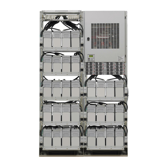
Vertiv™ NetSure™ -48 VDC Battery Tray Kit Installation Manual 1 NetSure™ -48V Battery Tray Kit 1.1 Kit Description This document provides installation instructions for the -48V Battery Tray Kits. The NetSure™ -48V Battery Tray Kit provides a battery tray for a 19" or 23” wide relay rack. The battery tray holds four (4) 12V front terminal valve regulated lead acid (VRLA) batteries. - Page 10 Vertiv™ NetSure™ -48 VDC Battery Tray Kit Installation Manual Table 1.2 Kit 588820200SK002 Qty. Description Battery Tray, 23” Mount, 21” Depth 58882020011 Circuit Breaker, 150 Amp 80VDC 100763 2-Pole Battery Disconnect Breaker Kit (Left) 559816 Kit, Battery lugs, 2 AWG, 90 deg, Short Tongue...
- Page 11 Vertiv™ NetSure™ -48 VDC Battery Tray Kit Installation Manual Table 1.5 Kit 582136700SK001 Qty. Description Battery Tray, 19” Mount 541034 Circuit Breaker, 100 Amp 80VDC 256695900 1-Pole Battery Disconnect Breaker Kit, (Left) 528501 3 ft 2 AWG Wire 104694 Jumper for Battery Disconnect Breaker Alarm...
- Page 12 Vertiv™ NetSure™ -48 VDC Battery Tray Kit Installation Manual Table 1.8 Kit 582136700SK008 Qty. Description Battery Tray, 19” Mount 559810 Circuit Breaker, 100 Amp 80VDC 256695900 1-Pole Battery Disconnect Breaker Kit, (Left) 559814 3 ft 2 AWG Wire 104694 Jumper for Battery Disconnect Breaker Alarm...
-
Page 13: Tools And Material Required
Vertiv™ NetSure™ -48 VDC Battery Tray Kit Installation Manual Table 1.11 Kit 60075329 Qty. Description Battery Tray, 23” Mount 559806 2 ft Heat Shrink Tubing 182778600 Battery Cables, 2 AWG, 15ft long 565456 Installation Instructions IM588820200SK001 Hardware, Miscellaneous 1.3 Tools and Material Required The following items are required to install this kit. -
Page 14: Mounting The Battery Tray
Vertiv™ NetSure™ -48 VDC Battery Tray Kit Installation Manual 1.4.1 Mounting the Battery Tray Procedure [ ] 1. To install a Battery Tray, perform the procedure in Figure 1.1. Figure 1.1 Mounting and Securing the Battery Tray onto the Rack 1. -
Page 15: Installing The Battery Disconnect Circuit Breaker Kit (If Equipped)
Vertiv™ NetSure™ -48 VDC Battery Tray Kit Installation Manual 1.4.2 Installing the Battery Disconnect Circuit Breaker Kit (If Equipped) Procedure [ ] 1. Remove the cover from the battery disconnect circuit breaker assembly. Secure the battery disconnect circuit breaker assembly to the battery tray using 6-32 x 1/2” screws and 6-32 KEPS nuts (2-places). Refer to Figure 1.2. -
Page 16: Installing And Connecting Batteries In The Battery Tray
Vertiv™ NetSure™ -48 VDC Battery Tray Kit Installation Manual 1.5 Installing and Connecting Batteries in the Battery Tray 1.5.1 Wiring to the Battery Tray DANGER! Adhere to the “Important Safety Instructions” presented at the front of this document. Procedure [ ] 1. -
Page 17: Installing And Connecting Batteries
Vertiv™ NetSure™ -48 VDC Battery Tray Kit Installation Manual 1.5.2 Installing and Connecting Batteries DANGER! Adhere to the “Important Safety Instructions” presented at the front of this document. Procedure NOTE! Refer to Figure 1.4 and Figure 1.5 as this procedure is performed. - Page 18 Vertiv™ NetSure™ -48 VDC Battery Tray Kit Installation Manual Figure 1.4 Battery Tray Installation Details Connect Link Furnished Connect Link Furnished Connect Link with Battery to these with Battery to these Furnished with Battery Two Terminals Two Terminals to these Two...
-
Page 19: Alarm Jumper Routing
Vertiv™ NetSure™ -48 VDC Battery Tray Kit Installation Manual Figure 1.5 Cable Routing - Battery Tray with Circuit Breaker Routes up to Routes up to (+) Input Battery (-) Input Battery Wire marked per battery tray [+1] or [+2] or [+3] or [+4]... - Page 20 Vertiv™ NetSure™ -48 VDC Battery Tray Kit Installation Manual NOTE! For the Vortex or NetSure 701 system, this is PIN 11 of TB1 (System Fuse Alarm Input) on the Interconnect/Inhibit Card on the right side of the base of the power system distribution cabinet. For NetSure 721 system this is PIN 1 of TB1 (Battery Tray FA) on the System Interface circuit card inside the distribution cabinet.
- Page 21 Vertiv™ NetSure™ -48 VDC Battery Tray Kit Installation Manual Connect with Vertiv on Social Media https://www.facebook.com/vertivI https://www.instagram.com/vertiv/ https://www.linkedin.com/company/vertiv/ https://www.twitter.com/vertiv/ Proprietary and Confidential © 2022 Vertiv Group Corp.
- Page 22 Vertiv.com | Vertiv Headquarters, 1050 Dearborn Drive, Columbus, OH, 43085, USA © 2022 Vertiv Group Corp. All rights reserved. Vertiv™ and the Vertiv logo are trademarks or registered trademarks of Vertiv Group Corp. All other names and logos referred to are trade names, trademarks or registered trademarks of their respective owners. While every precaution has been taken to ensure accuracy and completeness here, Vertiv Group Corp.
Need help?
Do you have a question about the NetSure 588820200SK001 and is the answer not in the manual?
Questions and answers