Table of Contents
Advertisement
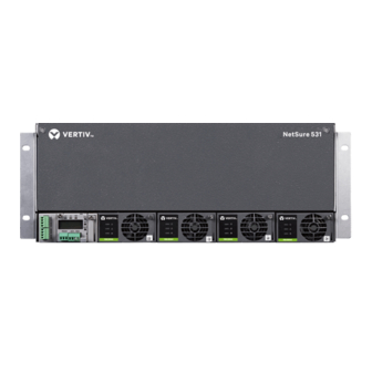
NetSure 531 A41, NetSure 531 A91 Subrack Power System
User Manual
Version
Revision date
BOM
Vertiv Tech provides customers with technical support. Users may contact the nearest Vertiv local sales
office or service center.
Copyright © 2017 by Vertiv Tech Co., Ltd.
All rights reserved. The contents in this document are subject to change without notice.
Vertiv Tech Co., Ltd.
Address: Block B2, Nanshan I Park, No.1001 Xueyuan Road, Nanshan District, Shenzhen, 518055,
P.R.China
Homepage: www.vertivco.com
E-mail: overseas.support@vertivco.com
V1.4
December 31, 2017
31012809
Advertisement
Table of Contents

Subscribe to Our Youtube Channel
Related Manuals for Vertiv NetSure 531 A91


Summary of Contents for Vertiv NetSure 531 A91
- Page 1 Revision date December 31, 2017 31012809 Vertiv Tech provides customers with technical support. Users may contact the nearest Vertiv local sales office or service center. Copyright © 2017 by Vertiv Tech Co., Ltd. All rights reserved. The contents in this document are subject to change without notice.
- Page 2 When operating Vertiv products, the safety rules in the industry, the general safety points and special safety instructions specified in this book must be strictly observed.
- Page 3 IV. ESD Notice The static electricity generated by the human body will damage the static sensitive elements on PCBs, such as large-scale ICs. Before touching any plug-in board, PCB or IC chip, ESD wrist strap must be worn to prevent body static from damaging the sensitive components.
- Page 4 BLVD The system has battery low voltage disconnection (BLVD) function. BLVD means when the mains fail and batteries supply power, the controller cuts the load off when the battery voltage drops down to below 43.2V to prevent over-discharge. The BLVD voltage is settable. Refer to ACU+ or NCU User Manual for setting method. The factory setting is enabling BLVD, which means that if power outage lasts for a long time or the power system fails, there might be BLVD.
-
Page 5: Table Of Contents
Contents Chapter 1 Overview ................................1 1.1 Composition And Configuration ..........................1 1.2 Features ................................2 Chapter 2 Installation Instruction ............................3 2.1 Safety Regulations ..............................3 2.2 Preparation ................................3 2.3 Mechanical Installation ............................4 2.4 Electrical Installation ............................. 6 2.4.1 Power System Cabling Method ......................... -
Page 7: Chapter 1 Overview
Chapter 1 Overview Chapter 1 Overview This chapter introduces composition, configuration, and features. The “power system” in this manual refers to the NetSure 531 A41 and NetSure 531 A91 series 19 inch subrack power system. 1.1 Composition And Configuration System composition The system consists of power distribution parts, rectifiers and controller. -
Page 8: Features
NetSure 531 A41, NetSure 531 A91 Subrack Power system User Manual... -
Page 9: Chapter 2 Installation Instruction
The equipment should be unpacked and inspected after it arrives at the installation site. The inspection shall be done by representatives of both the user and Vertiv Tech Co., Ltd.To inspect the equipment, you should open the packing case, take out the packing list and check against the packing list that the equipment is correct and complete. Make sure that the equipment is delivered intact. -
Page 10: Mechanical Installation
2. For the convenience of maintenance, users should maintain a clearance of 800mm at the front of the power system. 3. Subrack cannot be installed against the wall, it must leave enough space for heat dissipation. NetSure 531 A41, NetSure 531 A91 Subrack Power system User Manual... - Page 11 Figure 2-1 Cabinet and rack installation Installed in cabient Insert the subrack power system to the matching cabinet, as shown in Figure 2-2. Power subrack 电源插框 Figure 2-2 Installed in the cabinet system NetSure 531 A41, NetSure 531 A91 Subrack Power system User Manual...
-
Page 12: Electrical Installation
2.4 Electrical Installation 2.4.1 Power System Cabling Method Cabling from the top of the power system Epoxy board top cover and rubber ring top cover are optional for this system. NetSure 531 A41, NetSure 531 A91 Subrack Power system User Manual... - Page 13 Use the electrician's knife incise the "+" mark on the rubber unit. As shown in Figure 2-7. Latex unit Cable outlet area Figure 2-7 Cable entry Illustration of the DU unit NetSure 531 A41, NetSure 531 A91 Subrack Power system User Manual...
-
Page 14: Connecting Ac Input Cables
Take the NetSure 531 A41 power system as an example, the positions of the terminals are shown in Figure 2-10. AC output terminal N AC output terminal L Earthing screw AC input terminal N AC input terminal L Figure 2-10 Illustration of the connection terminal NetSure 531 A41, NetSure 531 A91 Subrack Power system User Manual... -
Page 15: Connecting Load Cables
1. If the AC input of the subrack is selected as terminal by user, there is no overcurrent and short circuit protection, and you should configure the overcurrent and short circuit protection in the previous level of the subrack. Please contact Vertiv Tech Ltd of local technical support for the device options. -
Page 16: Connecting Signal Cables
All the status changes should be verified by a multimeter. After the alarms are removed, the dry contacts should resume. NetSure 531 A41, NetSure 531 A91 Subrack Power system User Manual... - Page 17 Figure 2-15 IB2 extension board port definition Note 1. J11 and J12 are temperature sensor ports. They are not used here. 2. J2 is I C interface, and provides the power. NetSure 531 A41, NetSure 531 A91 Subrack Power system User Manual...
- Page 18 Digital inputs: 8-route, opto-isolation, the alarm and high/low level are definable (high level: 20V ~ 60V, low level: less than 1V). Digital output: 8-route, relay isolation, maximum: 30Vdc 1A, 125Vac 0.5A; 60W; minimum: 10uA @ 10Vdc, alarm is definable. NetSure 531 A41, NetSure 531 A91 Subrack Power system User Manual...
- Page 19 USB port Figure 2-17 M820B controller communication port The communication port of the M830B controller is shown in Figure 2-18. Ethernet port USB port Figure 2-18 M830B controller communication port NetSure 531 A41, NetSure 531 A91 Subrack Power system User Manual...
-
Page 20: Chapter 3 Commissioning
± 0.2V. Start and stop each rectifier of the system by unplugging and inserting each rectifier. Check their output voltages. NetSure 531 A41, NetSure 531 A91 Subrack Power system User Manual... -
Page 21: Basic Settings
Voltage)NetSure 531 A41-S1~S2: 48V/SET; Set the battery shunt coefficient for: 175A/25mV; NetSure 531 A41-S3: 48V/SET; Set the battery shunt coefficient for: 175A/25mV; NetSure 531 A91-S1: 48V/SET; Set the battery shunt coefficient for: 300A/25mV The DC over-voltage alarm point has been set correctly in factory before delivery, check that the setting... -
Page 22: Alarm Check And System Operation Status Check
If any defect is found in this equipment, inform the personnel responsible for the contract. If repairing is needed, please fill in the FAILURE REPORT and send the report together with the defective unit to the repairing center for fault analysis. NetSure 531 A41, NetSure 531 A91 Subrack Power system User Manual... -
Page 23: Chapter 4 Trouble Shooting
3. Power on the rectifiers one by one. 4. If the over-voltage protection is triggered when a certain rectifier is powered on, that rectifier is the faulty one. Replace it NetSure 531 A41, NetSure 531 A91 Subrack Power system User Manual... -
Page 24: Rectifier Fault Handling
Remove the object at the inlet or vent Rect Protect (yellow) Ambient temperature too high or the inlet too Decrease the ambient temperature or remove close to a heat source the heat source NetSure 531 A41, NetSure 531 A91 Subrack Power system User Manual... - Page 25 7. Certain functions (i.e. rectifier current limit, rectifier addressing) may require adjustment when adding or replacing a Rectifier Module. Refer to the Power System documentation for instructions. NetSure 531 A41, NetSure 531 A91 Subrack Power system User Manual...
-
Page 26: Appendix 1 Technical And Engineering Data
295 ± 5Vac by default, Lower than the AC input voltage protection and protection point 10Vac NetSure 531 A91, NetSure 501 A91: 295 ± 5Vac by default, 10Vac AC input over-voltage protection lower than the AC input over-voltage alarm point recovery point NetSure 701 A41: 285 ±... - Page 27 20Ka at 8/20µs, for the positive and negative polarities features respectively. The test interval is not smaller than 1 minute. It can also withstand one event of simulated lightning surge current of 40Ka at 8/20µs NetSure 531 A41, NetSure 531 A91 Subrack Power system User Manual...
- Page 28 NetSure 531 A41-S1/S2/S3: ≤ 25; Mechanical rectifiers and NetSure 531 A91-S1: ≤ 40 controller) Weight (kg) Subrack (without NetSure 531 A41-S1/S2/S3: ≤ 12; rectifiers and NetSure 531 A91-S1: ≤ 20 controller): NetSure 531 A41, NetSure 531 A91 Subrack Power system User Manual...
-
Page 29: Appendix 2 Installation Instruction Of Battery Rack
1) Install accessory 1 and accessory 2 according to Figure 2 (a). 2) Install accessory 3 according to Figure 2 (b). Accessory 1 Accessory 3 Accessory 2 Figure 2 Installation procedure of accessory 1 ~ accessory 3 NetSure 531 A41, NetSure 531 A91 Subrack Power system User Manual... - Page 30 2) Install accessory 5 according to Figure 4 (a). 3) Install accessory 2 and accessory 4 according to Figure 4 (b). Accessory 4 Accessory 2 Figure 4 Installation procedure of accessory 2, accessory 4 and accessory 5 NetSure 531 A41, NetSure 531 A91 Subrack Power system User Manual...
-
Page 31: Installation Instruction Of Three-Layer Battery Rack
1. Install accessory 1 and accessory 2 according to Figure 6 (a). 2. Install accessory 3 according to Figure 6 (b). Accessory 2 Accessory 1 Accessory 3 Figure 6 Installation procedure of accessory 1 ~ accessory 3 NetSure 531 A41, NetSure 531 A91 Subrack Power system User Manual... -
Page 32: Fixing The Battery Rack
1. Fix the battery rack to the ground according to the installation dimensions shown in Figure 8. The fixing bolts are accessories. Figure 8 Installation dimensions (unit: mm) 2. Fix the subrack power system onto the top of the battery rack. Refer to 2.3 Mechanical Installation. NetSure 531 A41, NetSure 531 A91 Subrack Power system User Manual... -
Page 33: Appendix 3 Wiring Diagram
TO the negative busbar of the module 2. Connected the X5-1 and the X6-1 to the cable of the temperature sensor for system configuration. Figure 9 NetSure 531 A41-S1 wiring diagram NetSure 531 A41, NetSure 531 A91 Subrack Power system User Manual... - Page 34 8-PL TO the negative busbar 2. Connected the X5-1 and the X6-1 to the cable of the temperature sensor for system configuration. Figure 10 NetSure 531 A41-S2 wiring diagram NetSure 531 A41, NetSure 531 A91 Subrack Power system User Manual...
- Page 35 1. Connected the X3-1 to the X3-2, connected X3-1 to the X3-2. 2. Connected the X5-1 and the X6-1 to the cable of the temperature sensor for system configuration. Figure 11 NetSure 531 A41-S3 wiring diagram NetSure 531 A41, NetSure 531 A91 Subrack Power system User Manual...
- Page 36 TO the negative busbar 2. Connected the X5-1 and the X6 -1 to the cable of the temperature sensor for system c onfiguration. Figure 12 NetSure 531 A91-S1 wiring diagram NetSure 531 A41, NetSure 531 A91 Subrack Power system User Manual...
-
Page 37: Appendix 4 Schematic Diagram
BLVD Contactor QFB1 Battery 1 QFB2 Positive Busbar Battery 2 DC SPD SPD2 M2433X2 AC Distribution Unit -48V DC Distribution Unit 1 Figure 13 Schematic diagram of NetSure 531 A41-S1 NetSure 531 A41, NetSure 531 A91 Subrack Power system User Manual... - Page 38 LLVD Contactor QFD5 QFA1 QFD8 KMD2 BLVD Contactor QFB1 Battery 1 QFB2 Battery 2 Positive Busbar AC Distribution Unit DC Distribution Unit Figure 14 Schematic diagram of NetSure 531 A41-S3 NetSure 531 A41, NetSure 531 A91 Subrack Power system User Manual...
- Page 39 QFB1 Battery 1 Positive Busbar QFB2 Positive Busbar Battery 2 AC Distribution Unit DC Distribution Unit 1 DC Distribution Unit 2 Figure 15 Schematic diagram of NetSure 531 A91-S1 NetSure 531 A41, NetSure 531 A91 Subrack Power system User Manual...
-
Page 40: Appendix 5 Glossary
Ph-A Phase A Password Rect Rectifier Shunt coeff Shunt Coefficient Supervision module (controller) Surge Protection Device SW Version Software Version System Temp Temperature Temp Comp Temperature Compensation Volt Voltage NetSure 531 A41, NetSure 531 A91 Subrack Power system User Manual...
Need help?
Do you have a question about the NetSure 531 A91 and is the answer not in the manual?
Questions and answers