
Related Manuals for Vertiv NetSure A50B50


Summary of Contents for Vertiv NetSure A50B50
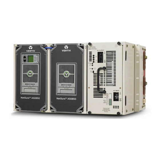
- Page 1 NetSure™ A50B50 DC Power Retrofit Installation and User Instructions Kit Specification Number: 588250400, A50IFRM 588250300, A50EFRM...
- Page 2 The information contained in this document is subject to change without notice and may not be suitable for all applications. While every precaution has been taken to ensure the accuracy and completeness of this document, Vertiv assumes no responsibility and disclaims all liability for damages resulting from use of this information or for any errors or omissions.
-
Page 3: Table Of Contents
Vertiv™ NetSure™ A50B50 DC Power Retrofit Installation and User Instructions TABLE OF CONTENTS Admonishments Used in this Document ......................... iv Important Safety Instructions ............................. v Static Warning ..................................viii 1 Document Set ..................................1 2 Description ................................... 1 3 Installation .................................... 1 3.1 Mounting ........................................................ -
Page 4: Admonishments Used In This Document
Vertiv™ NetSure™ A50B50 DC Power Retrofit Installation and User Instructions Admonishments Used in this Document will likely DANGER! Warns of a hazard the reader be exposed to that will result in death or serious injury if not avoided. (ANSI, OSHA) -
Page 5: Important Safety Instructions
Vertiv™ NetSure™ A50B50 DC Power Retrofit Installation and User Instructions Important Safety Instructions Safety Admonishments Definitions Definitions of the safety admonishments used in this document are listed under “Admonishments Used in this Document” on page iv. General Safety DANGER! YOU MUST FOLLOW APPROVED SAFETY PROCEDURES. - Page 6 Vertiv™ NetSure™ A50B50 DC Power Retrofit Installation and User Instructions Battery Refer to the battery manufacturer documentation for specific battery safety instructions. The following are general guidelines. WARNING! Correct polarity must be observed when connecting battery leads. WARNING! Special safety precautions are required for procedures involving handling, installing, and servicing batteries.
- Page 7 Vertiv™ NetSure™ A50B50 DC Power Retrofit Installation and User Instructions Personal Protective Equipment (PPE) DANGER! ARC FLASH AND SHOCK HAZARD. Appropriate PPE and tools required when working on this equipment. An appropriate flash protection boundary analysis should be done to determine the “hazard/risk” category, and to select proper PPE.
-
Page 8: Static Warning
Vertiv™ NetSure™ A50B50 DC Power Retrofit Installation and User Instructions Static Warning This equipment contains static sensitive components. The warnings listed below must be observed to prevent damage to these components. Disregarding any of these warnings may result in personal injury or damage to the equipment. -
Page 9: Document Set
2 Description Vertiv™ NetSure™ A50B50 DC Power Retrofit is a power solution comprising one or more frames that allow new-generation NetSure rectifiers to be installed in the -48V Modular Power Series rectifier shelves that house the older model A50B50 rectifiers. The new rectifiers can operate with or without the original rectifiers in the same system and the same shelf. - Page 10 Vertiv™ NetSure™ A50B50 DC Power Retrofit Installation and User Instructions Figure 3.1 Installing A50IFRM Intelligent Frame and A50EFRM Expansion Frame into the Existing Shelf A50EFRM Frames A50B50-based Rectifier Shelf location To remove front cover panels, remove (4) 8-32 x 1/2” screws Rectifier from each frame.
-
Page 11: Electrical Connections
Vertiv™ NetSure™ A50B50 DC Power Retrofit Installation and User Instructions 3.2 Electrical Connections Wiring Considerations The AC input, DC output, and system alarm connections on the frame mate with the existing connectors in the shelf. No adjustments or alterations are required for these connections. - Page 12 Vertiv™ NetSure™ A50B50 DC Power Retrofit Installation and User Instructions For CAN connections with only one A50IFRM and one A50EFRM, insert the termination plug into the right-hand CAN port of the A50EFRM. Alternatively, if the system is equipped with one or more SMTEMP modules, the fist SMTEMP module's CAN interface should be connected to the right-hand CAN port of the last A50EFRM.
- Page 13 Vertiv™ NetSure™ A50B50 DC Power Retrofit Installation and User Instructions Figure 3.4 CAN Connections in Multiple Shelves Multiple Shelves CAN Connection P/N 548451 6” CAN cable P/N 547520 24” CAN cable A50IFRM A50EFRM A50EFRM P/N 548451 6” CAN cable P/N 547520 24”...
- Page 14 Vertiv™ NetSure™ A50B50 DC Power Retrofit Installation and User Instructions Making IB2 Board Connections Digital inputs, relay outputs, and temperature probe(s) are connected to the IB2 Board. Refer to Figure 3.5 for connector locations, and Table 3.1 and Table 3.2 for pin-out information.
- Page 15 Vertiv™ NetSure™ A50B50 DC Power Retrofit Installation and User Instructions Figure 3.5 IB2 Board Connection IB2 Customer Interface Board To access connections, loosen this captive faster and pull board part way out. Relay Output Term. Blocks * Digital Input Term. Blocks ** Relay No.
- Page 16 Vertiv™ NetSure™ A50B50 DC Power Retrofit Installation and User Instructions Table 3.1 Digital Inputs Programmable Digital Pin No. Dedicated to... Input J3-2 User Defined J3-1 – J3-4 User Defined J3-3 – J3-6 User Defined J3-5 – J4-2 User Defined J4-1 –...
- Page 17 Vertiv™ NetSure™ A50B50 DC Power Retrofit Installation and User Instructions Table 3.2 Relay Outputs Alarms Assigned to Alarms Assigned to Programmable Relay this Relay this Relay Output IB2 Pin No. (Default) (Custom) J6-5 Any Major Alarm J6-3 Any Critical Alarm...
- Page 18 Vertiv™ NetSure™ A50B50 DC Power Retrofit Installation and User Instructions Installing and Connecting Optional Temperature Probe(s) Up to two (2) temperature probes can be connected to the Customer Interface (IB2) Board. See Figure 3.5 for connector location. NOTE! Each temperature probe consists of two pieces that plug together to make a complete probe. See SAG588250400 for part numbers and descriptions.
-
Page 19: Connecting An Optional Sm-Temp Module To The Ncu Can Bus
Vertiv™ NetSure™ A50B50 DC Power Retrofit Installation and User Instructions 3.2.1 Connecting an Optional SM-Temp Module to the NCU CAN Bus An SM-Temp Module can be connected to the NCU’s CAN Port located on the last retrofit frame. Refer to Figure 3.6 for port location and connections details. - Page 20 Vertiv™ NetSure™ A50B50 DC Power Retrofit Installation and User Instructions Figure 3.6 Connecting an Optional SM-Temp Module Connecting the SM-TEMP Module’s CAN Terminals to the NCU CAN Bus SM-TEMP Module ANALOG Cable P/N 562868 RJ-45 Note: Cable P/N 562868 is ordered separately.
- Page 21 Vertiv™ NetSure™ A50B50 DC Power Retrofit Installation and User Instructions Making CAN Interface Board Connections The CAN Interface Board allows for connecting the A50IFRM and A50EFRM frames together, or to terminate the last frame. This procedure has been previously described.
- Page 22 Vertiv™ NetSure™ A50B50 DC Power Retrofit Installation and User Instructions Table 3.4 TB1 Pin-outs PIN No. Signal Name Description - BAT Negative Battery + BAT Positive Battery LVD2_AUX LVD2 Feedback LVD2- LVD2 Drive Voltage, Negative LVD2+ LVD2 Drive Voltage, Positive...
-
Page 23: Installing The Controller
Vertiv™ NetSure™ A50B50 DC Power Retrofit Installation and User Instructions Table 3.5 Switch S1 Settings Switch S1 Settings Resistance Values of Group (See Settings Capable with Alarm and Control Panel(s), Part Table 5) No(s). Switch Position Open/ Close Open 437422100... - Page 24 Push the latch mechanism into the front panel of the NCU, and secure by tightening the captive fastener. This locks the NCU securely to the system. See Figure 3.11. After the NCU is powered on, the display shows the “Vertiv” screen. The controller is initializing. NOTE: The initialization routine takes several minutes.
- Page 25 Vertiv™ NetSure™ A50B50 DC Power Retrofit Installation and User Instructions Figure 3.11 Inserting the Controller into the A50IFRM...
- Page 26 Vertiv™ NetSure™ A50B50 DC Power Retrofit Installation and User Instructions Figure 3.12 NCU Main Menu Refer to the Controller User Manual (UM1M830BNA) for additional information. Set the date and time, site specific information (site name, location and system name), and battery capacity via the Quick Settings menu on the web interface.
-
Page 27: Installing The Rectifier
Vertiv™ NetSure™ A50B50 DC Power Retrofit Installation and User Instructions 3.2.3 Installing the Rectifier To install a Rectifier Module in a mounting frame, follow the procedure detailed below. The Rectifier Module is hot swappable. It can be installed or removed with the system operating. -
Page 28: Re-Installing The Front Cover Panel(S)
Vertiv™ NetSure™ A50B50 DC Power Retrofit Installation and User Instructions Figure 3.14 Latch Mechanism on the Rectifier Module Latch Handle 3.2.4 Re-installing the Front Cover Panel(s) After all the wiring is done, the front cover panel should be re-installed into the frame. Secure the front cover panel to the frame using the hardware previously disassembled. -
Page 29: Initially Starting, Configuring, And Checking System Operation
Vertiv™ NetSure™ A50B50 DC Power Retrofit Installation and User Instructions 4 Initially Starting, Configuring, and Checking System Operation 4.1 Initial Startup Preparation Ensure that every Rectifier Module mounting position is filled by a Rectifier Module. 4.2 Initially Starting the System •... -
Page 30: Checking System Status
If no alarms are present, contact the Network Operation Center (NOC) that the work has been completed and the alarm log for this site can be closed. If alarms are present, contact the Vertiv Technical Support desk. Contact information is located near the end of this... - Page 31 Vertiv™ NetSure™ A50B50 DC Power Retrofit Installation and User Instructions Connect with Vertiv on Social Media https://www.facebook.com/vertivI https://www.instagram.com/vertiv/ https://www.linkedin.com/company/vertiv/ https://www.twitter.com/vertiv/...
- Page 32 Vertiv.com | Vertiv Headquarters, 1050 Dearborn Drive, Columbus, OH, 43085, USA © 2021 Vertiv Group Corp. All rights reserved. Vertiv™ and the Vertiv logo are trademarks or registered trademarks of Vertiv Group Corp. All other names and logos referred to are trade names, trademarks or registered trademarks of their respective owners. While every precaution has been taken to ensure accuracy and completeness here, Vertiv Group Corp.
Need help?
Do you have a question about the NetSure A50B50 and is the answer not in the manual?
Questions and answers